Table of Contents
Advertisement
Quick Links
Advertisement
Table of Contents

Subscribe to Our Youtube Channel
Related Manuals for TOORX BRXOffice Compact


Summary of Contents for TOORX BRXOffice Compact
- Page 1 MANUALE d’ISTRUZIONI...
-
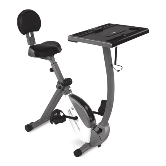
Page 2: Product Overview
PRODUCT OVERVIEW Meter Desktop Adjustment Knob Meter Seat Back Cushion Adjustment Knob Upright Back Support Back Frame Top Cover Lever Cover Right Pedal End Cap Levering Cap Front Stabilizer Wheel Right Crank Rear Stabilizer THEFOLLOWINGTOOLS ARE INCLUDED Wrench: FOR ASSEMBLY Allen Wrench (5mm) w/ Screwdriver:... -
Page 3: Hardware Identification Chart
HARDWARE IDENTIFICATION CHART Figure Description Carriage Bolt (M8 * 1.25 * 60mm) Carriage Bolt (M8 * 1.25 x*45mm) Bolt, Button Head (M6*1 *12mm) Screw, Round Head (M6* 12mm) Acorn Nut (M8*1.25) Arc Washer (M8) Washer (M8) Nut M8 Adjustment Knob Pull Pin... - Page 4 Place all parts from the box in a cleared area and position them on the floor in front of you. Remove all packing materials from your area and place them back into the box. Do not dispose of the packing materials until assembly is completed. Read each step carefully before beginning.
-
Page 5: Assembly Instruction
STEP 4: Attach the Seat (B24) to the Seat Post (A6) with Nylock Nuts (M8) (D25) and Washer (M8) (D38). Insert the Seat Post (B24) into the Main Frame (A1) and secure with the Adjustment Knob (D1). NOTE: 1. Make sure that the pin on the Adjustment Knob (D1) is inserted into one of the holes in Seat Post (B24). - Page 6 STEP 6: Attach the Desktop post (A4) to the Desktop (B10) with Button Head Bolts (M8*1.25*12mm) (D14) and Washer (M8) (D24). STEP7: Insert the Desktop Post (A4) into the Upright (A3) and secure with the Adjustment Knob (D1). Bolt the Round Head Bolt (M6*1*12 mm) (D17) onto the Upright (A3) for security. NOTE: 1.
- Page 7 STEP 9: Lock and tight the Left Pedal (B27) and Right Pedal (B28) on the Left Crank (B29) and Right Crank (B30) by using the Wrench. FUNCTION INSPECTION: Visually inspect the Bike to verify that assembly is as shown in the above illustration. Check the function of the Bike by turning the c rank s lowly through one complete revolution to verify that the drive train functions properly.
- Page 8 OPERATIONAL INSTRUCITONS USING THE FITNESS METER MODE: This key lets you to select and lock on to a particular function you want. SET(IF HAVE) :To set the values of time. distance and calories when not in scan mode. RESET/CLEAR (IF HAVE): The key to reset the value to zero by pressing the key .
- Page 9 HOW TO INSTALL AND REPLACE BATTERIES Open the Meter (C1) by using the Shaped Wrench (D3). The meter operates with two AAA batteries, the batteries are not included. After changing the batteries, push the Meter (C1) back and press down to reset. Front Back NOTE:...
-
Page 10: Load Adjustment
LOAD ADJUSTMENT To increase the load, turn the 8 Section Adjustment Knob (B32) clockwise. To decrease the load, turn the 8 Section Adjustment Knob (B32) counterclockwise. There are eight levels for the load adjustment. SEAT ADJUSTMENT Proper seat adjustment is important. Turn the Adjustment Knob (D1) to loosen, then pull the Adjustment Knob (D1) to release the pin. - Page 11 OPERATIONALINSTRUCTIONS STORAGE • To store the BIKE, simply keep it in a clean dry place. • To avoid damage to the electronics, remove the batteries before storing the BIKE for one year or more. • Follow the illustrated process below to fold the BIKE. Remove the Pull Pin (D2), fold the Rear Frame (A2) forward.
- Page 12 OPERATIONALINSTRUCTIONS UPRIGHT ADJUSTMENT Refer to the illustrations bel o w . T h e a n g l e o f t h e M e t e r ( B 1 0 ) can be set to different angles from Position 1 to Position 5. Lift the Lever cover (B6) up using your right foot, adjust the UPRIGHT (A3)/ M e t e r ( B 1 0 ) to desired position.
- Page 13 TOCONTACTCUSTOMERSERVICE...
-
Page 14: Parts List
PARTS LIST TOCONTACTCUSTOMERSERVICE A. Welding Parts Description Main Frame Rear Frame Upright Table Support Front Stabilizer Seat Support Back Support Back Frame Rear Stabilizer Lever Magnetic Bracket Folding Axis B. Plastic Parts Description Left Chain Cover Right Chain Cover Middle Cover Left Front Cover Right Front Cover Lever cover... - Page 15 Plastic Washer Φ10.2*Φ14 Stopper TOCONTACTCUSTOMERSERVICE End Cap Bearing Housing Hand grip Plug C. Electrical parts Description Meter Connection Wire Folding Axis Left Crank Flywheel Flywheel V-ribbed Belt (230J) V-ribbed Belt (240J) Pulley W/Shaft Pulley Shaft Pulley Sensor Ball Bearing (6000ZZ) Ball Bearing (6200ZZ) Ball Bearing (6003ZZ) Idler Shaft...
- Page 16 Screw, Round Head Self-Tapping ST4.2X25 Flange Nut M10 x 1.25 TOCONTACTCUSTOMERSERVICE Acorn Nut M8 Arc Washer M8 Washer M8 Nylock Nut M8 Nut M10 U-Shape Bracket Nylock Nut M6 C Ring Φ17.0 C Ring Φ10 Wave Spring Washer S17 Spring Washer (M8) Large Washer (ø8.2 x ø25 x 2mm) Nut M10 Carriage Bolt M4X10...
- Page 17 GARLANDO SPA Via Regione Piemonte, 32 - Zona Industriale D1 15068 - Pozzolo Formigaro (AL) - Italy www.toorx.it - info@toorx.it...
Need help?
Do you have a question about the BRXOffice Compact and is the answer not in the manual?
Questions and answers