Table of Contents
Advertisement
Quick Links
Advertisement
Table of Contents

Related Manuals for JOYTECH PY1400ACL


Summary of Contents for JOYTECH PY1400ACL
- Page 1 PY1400ACL Sliding Gate Opener User Manual 2017...
-
Page 2: Safety Instruction
Dear users, Thank you for choosing this product. Please read the manual carefully before assembling and using it. Please do not leave out the manual if you send this product to a third party. 1. Safety Instruction Please ensure that the using power voltage matches with the supply voltage of gate opener (AC110V or AC220V);... - Page 3 2. Packing List (standard) Picture Name Quantity Main engine Manual release bar Remote control Mounting accessories box Sprocket cover Chain link Chain Tie rod Square screw Round screw...
- Page 4 Picture Name Quantity Door connecting plate Horizontal mounting plate Vertical mounting plate 4-10 Foundation bolt M8 Magnetic or Spring limit 4-11 switch block Inner hexagon screw 4-12 M6×20 Hexagon screw M6×65 4-13 Hexagon screw M8×25 Nut M6 4-14 Nut M8 Flat washer φ6 4-15 Flat washer φ8...
-
Page 5: Technical Parameters
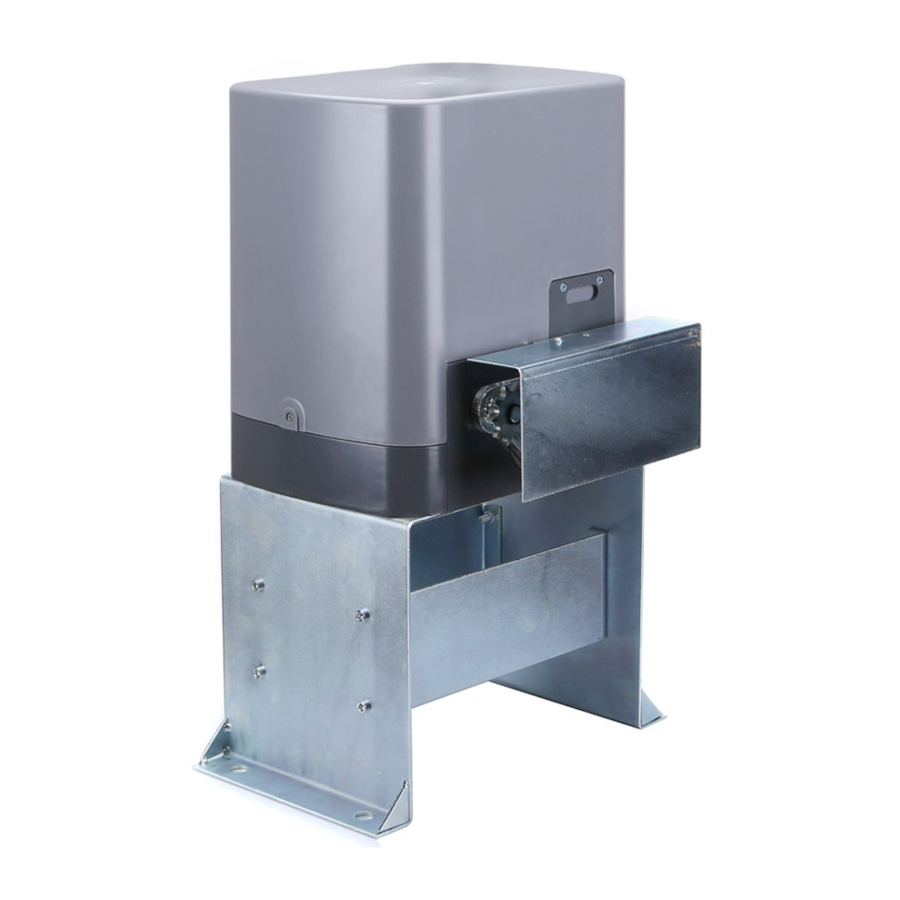
26.5Kg 4. Installation PY800ACL/PY1400ACL sliding gate opener is applicable to gate weight less than 800kg/1400kg, and length of the sliding gate should be less than 14m/20m. The drive mode adopts the gear and rack transmission. This gate opener must be installed inside the enclosure or yard for protection. - Page 6 ⑤ ④ ③ ② ⑥ ⑦ ⑧ ① Figure 1 ① Gate opener; ② Wireless keypad (optional); ③ Gate; ④ Infrared sensor (optional); ⑤ Alarm lamp (optional); ⑥ Safety stop block; ⑦ Chain; ⑧ Remote control; 4.2 Size of main engine and accessories 4.2.1 Size of main engine Figure 2...
- Page 7 Please cast a concrete pedestal with the size of 550mm x 400mm and depth of 200mm in advance, Please verify whether the distance so as to firmly install PY800ACL/PY1400ACL gate opener. between the gate and gate opener is suitable before casting the pedestal.
- Page 8 4.3.2 Main engine installation a) Dismantle the plastic housing on the main engine before installation and keep relevant fasteners properly; b) If select the detachable mounting base, the base should be assembled first as shown in Figure 5; Flat Flat washer washer φ...
- Page 9 lower than 1.5mm² and the length shall be determined by users according to the field situation) due to different installation environments; e) Please unlock the main engine before installation, the unlock method is: take out the key cover, insert the key, and open the manual release bar till it rotates by 90° as shown in Figure 7. Then turn the output sprocket and the sprocket can be rotated easily;...
- Page 10 Tie rod Chain Chain Chain Chain link link Figure 8 If door frame is round, please use the round screw as shown in Figure 9: Flat washer φ 8 Spring washer φ 8 Nut M8 Tie rod Nut M6 Spring washer φ 6 Flat washer φ...
- Page 11 Installation of chain, small and big sprocket as shown in Figure 11: Figure 11 Installation of sprocket cover as shown in Figure 12: Cross Cross screw screw M4×10 M4×10 Sprocket Sprocket cover cover Figure 12...
-
Page 12: Limit Switch Adjustment
The distance between main engine and chain ends should be at least 30CM, as shown in Figure 13: ≥30CM ≥30CM Figure 13 Warnings ·To ensure safety, install safety stop blocks on both ends of the rails to prevent the gate out of the rail. Before installing the main engine, make sure that the safety stop blocks are in place and whether it has the function of preventing the gate from moving out of the rail and out of the safety range. - Page 13 Installation of Spring limit switch bock: Gate Gate Spring Spring limit limit switch switch block block Hexagon Hexagon screw screw M6 × 65 Chain Chain Figure 14 Main Main engine engine Spring Spring Spring Spring limit limit switch switch block block Chain Chain...
- Page 14 Installation of magnetic limit switch bock: Gate Gate Magnet Magnet Magnetic Magnetic limit limit switch switch block block Chain Chain Figure 16 ≤20mm Main Main engine engine Magnet Magnet Magnetic Magnetic limit limit switch switch block block Chain Chain chain chain wheel wheel Gate...
-
Page 15: Wiring Instruction
4.3.5 Control board wiring 4.3.5.1 Standard control board Lamp Lamp Capacitor Capacitor Motor Motor Power Power Earth Earth D2 D1 D1 C C W U V PE PE N L 10A 250V 250V 24VDC 24VDC 24VDC 24VDC Infrared Infrared sensor sensor CLLM CLLM... - Page 16 DIP Switch 1. External button switch. ON - Three button switch; OFF - One button switch (X7 terminal CLS button can be used to circularly control the main engine OPEN/STOP/CLOSE/STOP). 2. Automatic close time. 3. Automatic close time. 2 ON 3 OFF: automatic close time is 15s, 2 OFF 3 ON: automatic close time is 30s, 2 OFF 3 OFF: automatic close time is 45s, 2 ON 3 ON: no automatic close function.
- Page 17 Adjustment and operation Remote control operation Remote control is single button mode, one same button on the remote control to circularly control the main engine OPEN/STOP/CLOSE/STOP. OPEN OPEN CLOSE CLOSE STOP STOP Figure 20 Add extra remote control (remote control learning): Remove the upper cover of main engine, remove the upper cover of the control box, press the learning button AN1 on the control board, and indicator light LED2 will flash once and then go out;...
- Page 18 4.3.5.1 Intelligent control board Hall Hall line line Limit Limit switch switch Loop Loop detetcor detetcor Infrared Infrared sensor sensor 12VDC 12VDC Pedestrian Pedestrian switch switch Capacitor Capacitor O/S/C O/S/C switch switch External External button button switch switch MOT1 MOT1 MOT2 MOT2 Lamp...
- Page 19 J5 (For the convenience of wiring, this terminal is accompanied with failure diagnosis light) 7. Power supply for fittings: +12V Electric current ≤100mA) ( 8. Photocell input (N.C.); short out the device if not used. 9. GND 10. Loop detector (sensor coil) connector (N.O.) In the closing process, once vehicles are detected by the loop detector, the gate will open soon;...
- Page 20 VR4: For motor output force adjustment to keep safe usage. Clockwise rotation to increase, counter-clockwise rotation to reduce. Note: the default setting is VR1, VR2, VR3, VR4 are the maximum value, and the user can adjust according to the actual requirement. Warning: the motor output force cannot set too large, just to be able to drive the gate.
- Page 21 Adjustment and operation Remote control operation Remote control is single button mode, one same button on the remote control to circularly control the main engine OPEN/STOP/CLOSE/STOP. OPEN OPEN CLOSE CLOSE STOP STOP Pedestrian Pedestrian mode mode Figure 24 Add extra remote control (remote control learning): Remove the upper cover of main engine; press the learning button S1 on the control board, and indicator light LEARN will flash once and then go out;...
-
Page 22: Troubleshooting
5.2 Troubleshooting Problems Possible Reasons Solutions 1.Switch on the power supply. 1.The power is off. The gate cannot open or 2.Check the fuse (code FU), 2.Fuse is burned. close normally, and LED change the fuse if burnt. 3.Control board power wiring with does not light. - Page 23 Connect external receiver Remote control working Signal is blocked. antenna, 1.5 meters above distance is too short. ground. 1.Motor output force is not enough The gate moves to the (Intelligent type). 1.Adjust the VR4. middle position to stop 2.Sensitivity of obstacle is too 2.Adjust the VR1.
Need help?
Do you have a question about the PY1400ACL and is the answer not in the manual?
Questions and answers