Advertisement
Quick Links
Advertisement

Related Manuals for JOYTECH PK300DC


Summary of Contents for JOYTECH PK300DC
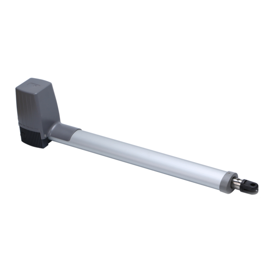
- Page 1 PK300DC/PK350DC Swing Gate Opener User Manual...
-
Page 2: Safety Instruction
Dear users, Thank you for choosing this product. Please read the manual carefully before assembling and using it. Please do not leave out the manual if you send this product to a third party. 1. Safety Instruction Please ensure that the using power voltage matches with the supply voltage of gate opener (AC110V or AC220V);... - Page 3 2. Packing List (standard) Picture Name Quantity Main engine Manual release bar Remote control Control box Wall bracket Front mounting bracket Connecting bracket Mounting screw (short) Mounting screw (length) Screw M8×25 Nut M8 Limit stopper...
-
Page 4: Technical Parameters
2. Packing List (optional) Picture Name Quantity Infrared sensor Wireless keypad Alarm lamp Electronic lock Storage battery 3. Technical Parameters PK300DC Model PK350DC 220V/50Hz;110V/60Hz Power supply 220V/50Hz;110V/60Hz Motor power 18~22 second per 90 (approx) Gate moving speed 18~22 second per 90 (approx) 300Kg Max.single-leaf weight... -
Page 5: Installation Drawing
4. Installation PK300DC/PK350DC swing gate opener is applicable to single leaf gate weight less than 300kg, and length of the single leaf swing gate should be less than 2.5m/3m. The drive mode adopts the worm and worm gear to combine the screw rod transmission. This gate opener must be installed inside the enclosure or yard for protection. - Page 6 4.2 Size of Main Engine and Accessories 4.2.1 Size of Main Engine 620M in 970M ax PK300DC 820M in 1370 Max PK350DC Figure 2...
- Page 7 PVC pipe laying motor, power cable, and control cables, and separate two PVC pipes to lay (motor and power cable) and (control cable), respectively. Mounting brackets In order to install the PK300DC / PK350DC main engines firmly, recommend to use the expansion screws to fix the mounting brackets. 4.3.2 Accessory a) Before installing the main engine, install the wall bracket on the wall, then fix the connecting bracket, and install the front mounting bracket on the door.
- Page 8 Hexagon screw Expansion screw Hexagon screw Figure 4 b) The connecting bracket and the wall bracket can be connected according to different conditions, as shown in figure 5. Figure 5 Users shall prepare power cables for the control box and main engines, according to different installation environment, the power cable of the control box is not less than 3 cores, and the power cable of the control box with 2 cores.
- Page 9 Left engine Right engine Figure 6 4.3.3 Main Engine Installation As shown in Figure 7, the tail of the main engine and the connecting bracket are fixed together through the installation of screws, and then manually adjust the telescopic arm to the appropriate length, and finally fix the telescopic arm connector and the front mounting bracket with the installation screws.
- Page 10 Installation direction: door opens inward (PK300DC) Note: Note: Limit Limit stopper stopper must must be be installed installed L=620+5 L=620+5 K < 620+340 620+340 Figure 8 100 110 120 130 140 150 160 170 180 190 200 Max 120° Max 110°...
- Page 11 Installation direction: door opens outward (PK300DC) Note: Note: Safety Safety stopper stopper must must be installed, installed, is is provied provied by by installer installer L=620+5 L=620+5 K < 620+340 620+340 Note: Note: Limit Limit stopper stopper must must be...
- Page 12 Installation direction: door opens inward (PK350DC) Note: Note: Limit Limit stopper stopper must must be be installed installed L=820+10 L=820+10 K < 820+540 820+540 Figure 12 100 120 140 160 180 200 220 240 260 280 300 Max 120° Max 110° Max 100°...
- Page 13 Installation direction: door opens outward (PK350DC) Note: Note: It It is is recommended recommended to to install install with with a safety safety stopper stopper (should (should be be prepared prepared by by the the users users themselves) themselves) L=820+10 L=820+10 K <...
- Page 14 4.3.4 Size of Control Box 127.5 Figure 16 Warnings ·To ensure safety, when door open facing outward, the safety block must be installed at the OPEN limit position to prevent the door opening angle from exceeding the machine range; the safety stopper must be installed at the CLOSE limit position, to make two doors stopping at the CLOSE limit position accurately (as shown in figure 10, 14).
- Page 15 4.3.5 Control Board Wiring Figure 17 1.Antenna 2. Antenna's shield 3. Start input (NO) It completely opens the gate 4. Pedestrian start in. (NO) It opens just motor 2 5. Common...
- Page 16 6. Photocell input (NC) During pause: Reloads pause During closing: Reverses motors direction 7. Photo stop input (NC) During pause: Reloads pause. During closing: Reverses motors direction. During opening: stops the motors and waits till contact returns close. 8. Analog opening edge input (8K2 ohm) Waiting an opening command: inhibits opening During opening: reverses motor direction for 1 second.
- Page 17 Inputs status When the control unit is in standby. User can read inputs status on display: _ _: No input active. 5t: Stop input active. P5: Photo stop input active. Pc: Photocells input active. EO: Analogic edge opening input active. EC: Analogic edge closing input active.
- Page 18 Slow stop is activated after travel setting, if slow stop speed is too slow, please adjust ‘TR1’ to increase. If slow stop speed is too fast, please adjust ‘TR1’ to decrease. Note: If the door is no need to be fully opened, please install the limit stopper at the proper position.
- Page 19 Base Menu Description: Operating logic OL: Select OL and push enter, with up/down select wanted logic between following end push once enter. Check tab operating logic for further information. 5T: Step by step logic. At: Automatic closing with stop function. CD: Automatic closing for condominium function.
- Page 20 DM Dead man mode: Selecting this menu it’s possible to control each motor in dead man mode. Push up and down to select one of following item: O1 open motor1 C1 close motor1 Q1 open motor2 C2 close motor2 EX Exit Keep pushed enter to start the selected motor in dead man mode.
- Page 21 Figure 20 Advanced menu TM working times menu: In this menu it’s possible to modify working times of control unit: T1- Working time motor1 51- Start time slowdown motor1 T2- Working time motor2 52- Start time slowdown motor2 DO-Motors delay opening DC- Motors delay closing TL-Electric lock activation menu.
- Page 22 D2 Load defaults: Choosing this menu and confirming with yes (YS), set the control unit at factory defaults. RC release torque at work end: Enabling this function, the motors reverse direction for a while to release the torque at end of work .Use up/down to choose yes(YS),not (NT) or exit(EX).
- Page 23 Default settings (Factory presets) Herr it follows list default settings. The same set after a D2 command of advanced menu. Figure 20...
- Page 24 5. Others 5.1 Maintenance Check whether the gate operates normally every month. For the sake of safety, each gate is suggested to be equipped with infrared protector, and regular inspection is required. Before installation and operation of the gate opener, please read all instructions carefully. Our company has the right to change the instruction without prior notice.
-
Page 25: Troubleshooting
5.2 Troubleshooting Problems Possible Reasons Solutions 1.Switch power 1.The power is off. supply. The gate cannot open 2.Fuse is burned. 2.Check the fuse, change the or close normally, and 3.Control board power wiring fuse if burnt. Display does not light. with problem. -
Page 26: Warranty
Warranty Warranty Ordinance 1. To repair against this warranty card and invoice during the warranty period. 2. Warranty period: 1 year after the date of invoice. 3. Without unauthorized dismantling, any product broken or damage due to quality problem, we’ll offer the repair service for free or replace for free.
Need help?
Do you have a question about the PK300DC and is the answer not in the manual?
Questions and answers