Table of Contents
Advertisement
Advertisement
Table of Contents

Subscribe to Our Youtube Channel
Related Manuals for JOYTECH SW300DC


Summary of Contents for JOYTECH SW300DC
- Page 1 SW300DC Swing Gate Opener User Manual...
-
Page 2: Table Of Contents
CONTENTS: 1. Safety Instruction........................1 2. Packing List..........................2 3. Technical Parameters ........................4. Installation Drawing.........................4 5. Tools Needed for Standard Installation..................4 6. Cable List..........................5 7. Direction of Gate Opening.......................6 7.1 Gate Opens Inwards........................6 7.2 Gate Opens Outwards........................6 8. Installation Steps........................7 Preparation before Main Machine Installation ................7 8.1.1 Cable Bury.........................7 8.1.2 Mounting Brackets Fixing......................7... -
Page 3: Safety Instruction
Dear users, Thank you for choosing this product. Please read the manual carefully before assembling and using it. Please do not leave out the manual if you send this product to a third party. 1. Safety Instruction Please read this manual carefully before installation, in which involves with important information about ... -
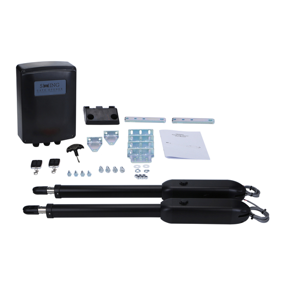
Page 4: Packing List
2. Packing List (Standard) Picture Name Quantity Main machine Control box Manual release key Remote control Wall bracket Front mounting bracket Connecting bracket Screw M8X25 Mounting screw (short) Screw M8×45 Self-locking Nut M8 Limit stopper... -
Page 5: Technical Parameters
Due to the difference of installation environment, our company does not provide the installation accessories to fix and connect gate openers and wall. Please prepare the these installation accessories according to actual site situation. 3. Technical Parameters Model SW300DC Power supply 220V/50Hz;110V/60Hz Motor power 18~22s/ 90°... -
Page 6: Installation Drawing
4. Installation Drawing Figure 1 SW300DC swing gate opener is applicable to single leaf gate weight less than 300kg, and the length shorter 2.5m. The drive mode adopts planetary transmission to combine with the screw rod transmission. than This gate opener must be installed inside the enclosure or yard for protection. -
Page 7: Cable List
6. Cable List Cable Application Cable Material Max. Length 3×2.5mm² (>30m) Cable of 220V controlbox’s power supply Unlimited 3×1.5mm² (<30m) Cable of gate opener’s power supply 2×1.5mm² Cable of infrared sensor 2×0.5mm² Cable of alarm lamp 2×0.5mm² Cable of electric lock 2×0.5mm²... -
Page 8: Direction Of Gate Opening
7. Direction of Gate Opening 7.1 Gate Opens Inwards Figure 2 100mm 120 mm 140 mm 160 mm 180 mm 200 mm 100mm 102° 101° 99° 98° 97° 97° 120mm 111° 108° 106° 104° 103° 99° 140mm 118° 115° 112° 102°... -
Page 9: Installation Steps
8.1.2 Mounting Brackets Fixing In order to install the SW300DC main machines firmly, it is recommended to use the expansion screws to fix the mounting brackets. 8.2 Accessory Installation A) Before installing the main machines, please install the wall bracket on the wall first, then fix the connecting bracket, finally install the front mounting bracket on the gate. - Page 10 Figure 4 B) The connecting bracket and the wall bracket can be connected according to different conditions, please refer to figure 5. Figure 5 C) Before the installation, please unlock the two main machines. Unlock method: Open the manual release cover, insert the manual release key, rotate the key until it’s released, as shown in Figure 6, then turn the telescopic arm, you’ll find it’s stretched by hand easily.
- Page 11 Figure 7 E) As shown in figure 8 below, connect wall bracket with wall according to marked position. Then, connect main machine with wall bracket by screw and nut. (Please use spirit level to make sure the installation levelness.) Figure 8 Figure 9...
-
Page 12: Dimension Of Control Box
8.3 Dimension of Control Box Figure 10 Note To ensure safety and protect the machines, please install a gate stopper at the open limit position when the gate opens outward to prevent the gate from running over its travel. Meanwhile, to enable the 2 swings to close to its accurate limit position, please install a limit stopper at the closed limit position (as shown in figure 3). -
Page 13: Wiring And Debugging
9. Wiring and Debugging 9.1 Wiring Instructions FUSE FUSE 10A Mains Mains input input AC24VIN AC24VIN +SOLAR- +SOLAR- +BATT- +BATT- FORCE FORCE SLOW SLOW DOWN DOWN SPEED SPEED PROG PROG + - MOTOR1 MOTOR1 MOTOR2 MOTOR2 -ELOCK+ -ELOCK+ -BLK+ -BLK+ 12V COM EM1 LM1 LM1 EM2... -
Page 14: Control Board Drawing And Instructions
9.2 Control Board Drawing and Instructions AC24VIN AC24VIN +SOLAR- +SOLAR- +BATT- +BATT- FORCE FORCE SLOW SLOW DOWN DOWN SPEED SPEED PROG PROG + - MOTOR2 -ELOCK+ -ELOCK+ -BLK+ -BLK+ MOTOR1 MOTOR1 MOTOR2 12V COM EM1 LM1 LM1 EM2 EM2 LM2 PH PED COM OSC GND ANT... -
Page 15: Digital Screen Setting
9.3 Digital Screen Setting When the control board is working, the users can check working state of gate opener by digital screen on the control board. : no input; : under opening state; : under closing state; : error; :manual mode; : travel setting;... -
Page 16: Trimmer Setting
9.5 Trimmers Setting Obstacle Sensibility Trimmer To adjust the sensitivity of obstacle -- clockwise to increase, counterclockwise to reduce the sensitivity of obstacle. If there are environmental effects, such as heavy winds, adjust the trimmer according to environment. Slow Speed Distance Trimmer To adjust slow speed distance -- clockwise to increase, counterclockwise to decrease slow speed distance. -
Page 17: Special Remote Control Key-Button
9.6.3 Special Remote Control Key-button Press and hold the combination keys for 5S. C(stop)+D(single gate) combination key -- enter into remote control learning. 9.7 Control Board Settings 9.7.1 Base Menu Press "PROG" to enter into base menu; Digital screen shows “NE”, select other functions of this menu by “+” and “-” buttons. Press "SET"... - Page 18 Dual gates single channel mode Remote control mode Four channel mode Single gate single channel mode Delete remote control...
-
Page 19: Base Menu Instruction
9.7.2 Base Menu Instruction Menu Option Default/Attention Press "PROG" to enter Press “+”(up) or “-”(down) to select; into base menu. Press “SET” to confirm. Standard mode; O/C/S (Open/Close/Stop). O/S/C standard mode with automatic closing function. When the gate opens, it will automatically close after automatic closing time. - Page 20 00-10: Open gate time interval is 0-15 seconds(default 3 seconds). If the interval 3 seconds. Open Gate Time Interval shorter than 2 seconds, then the electric lock cannot be used. Automatic closing time can be set as Automatic Closing Time 15 seconds.
-
Page 21: Advanced Menu
9.7.3 Advanced Menu Instruction Long press "PROG" 2 seconds to enter into advanced menu. Digital Screen shows “TL”, press “+”(up) or “-”(down) to select; Short press “SET” to confirm or to enter into sub-menu. Short press “PROG” to exit. If no command for one minute, the menu will automatically exit. Advanced Menu Time of of gate 1 Initial screen... - Page 22 Stop block Limit switch mode Hall sensor SW400DC Gate opener secection SW300DC SW200DC Default setting cancellation Factory default setting Factory default setting...
-
Page 23: Advanced Menu Instruction
9.7.4 Advanced Menu Instruction Menu Option Default/Attention Long press "PROG" 2 seconds Press “+”(up) or “-”(down) to select; to enter into base menu. Press “SET” to confirm. After automatic learning, the trip is not ideal can be adjusted manually, the Time of of gate1 shorter the time deceleration distance Travel time adjustment... - Page 24 Stop block.(Default) Stop block. Limit Switch Mode Hall sensor. SW400DC. SW300DC. (Default) SW300DC. Gate Opener Secection SW200DC. Cancel factory default setting. Factory Default Setting Factory default setting completes.
-
Page 25: Others
10. Others 10.1 Maintenance Check whether the gate operates normally every month. For the sake of safety, each gate is suggested to be equipped with infrared protector, and regular inspection is required as well. Before installation and operation of the gate opener, please read all instructions carefully. We reserve the right to change the instruction without prior notice. - Page 26 Warranty Warranty Ordinance 1. To repair against this warranty card and invoice during the warranty period. 2. Warranty period: 1 year after the date of invoice. 3. Without unauthorized dismantling, any product broken or damage due to quality problem, we’ll offer the repair service for free or replace for free.
Need help?
Do you have a question about the SW300DC and is the answer not in the manual?
Questions and answers
WHICH IS TYHE POS N DEG FOR A SINGLE GATE OPENER
My gate has a problem on the Display says E8 what sould i do