
Related Manuals for Badger Meter Hedland PE


Summary of Contents for Badger Meter Hedland PE
- Page 1 Variable Area Flow Meters Inline Liquid Flow Meter User Manual VAM-UM-00551-EN-03 (September 2014) 1.800.561.8187 information@itm.com www. .com...
- Page 2 Variable Area Flow Meters, Inline Liquid Flow Meter Page ii September 2014 1.800.561.8187 information@itm.com www. .com...
-
Page 3: Table Of Contents
User Manual CONTENTS Introduction . . . . . . . . . . . . . . . . . . . . . . . . . . . . . . . . . . . . . . . . . . . . . . . . . . . . . . . . . . . . . . . . . . . . . . . . . 4 Product Unpacking and Inspection . -
Page 4: Introduction
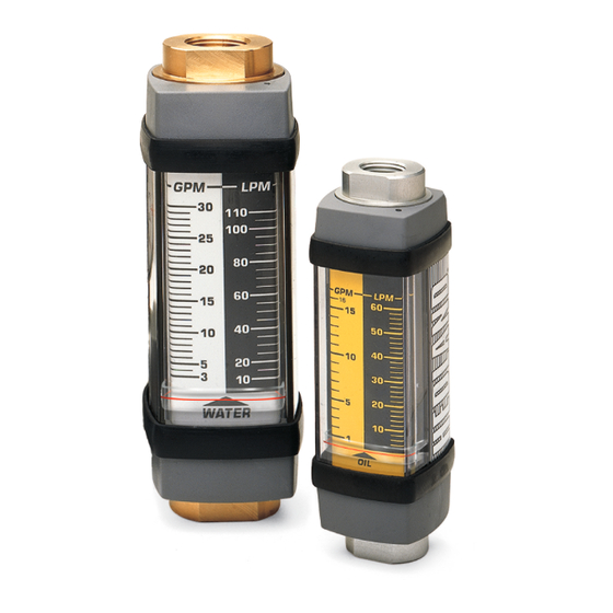
Introduction INTRODUCTION The Inline Liquid Flow Meter is a rugged industrial class inline flow rate indicator, offered in aluminum, brass or stainless steel models to monitor a wide variety of liquids . Available in seven port sizes from 1/4… 3" for flow ranges from 0 .02…0 .20 gpm (0 .1…0 .75 lpm) through 20…300 gpm (100…1100 lpm), the meters are calibrated at 0 .876 specific gravity for oil or other petroleum-based fluids, 1 .0 for water or other water-based fluids, or 1 .18 for phosphate ester liquids . -
Page 5: Operating Principle
Operating Principle OPERATING PRINCIPLE The flow meter is a variable area instrument . A sharp-edged orifice, located within the piston assembly, forms an annular opening with the contoured metering cone . The piston assembly carries a cylindrical PPS/ceramic magnet that is magnetically coupled to an external indicating magnet... -
Page 6: Installation
Installation INSTALLATION THIS PRODUCT SHOULD BE INSTALLED AND SERVICED BY TECHNICALLY QUALIFIED PERSONNEL TRAINED IN MAINTAINING INDUSTRIAL CLASS FLOW INSTRUMENTATION AND PROCESSING EQUIPMENT. READ INSTRUCTIONS THOROUGHLY BEFORE INSTALLING THE UNIT. IF YOU HAVE ANY QUESTIONS REGARDING PRODUCT INSTALLATION OR MAINTENANCE, CALL YOUR LOCAL SUPPLIER FOR MORE INFORMATION. OIL METERS ARE NOT RECOMMENDED FOR WATER MONITORING APPLICATIONS. -
Page 7: Installing The Flow Meter
Installation • Do not install the flow meter near turbulence producing fittings such as elbows, reducers, close coupled valves, etc . The inline flow meter does not require flow straighteners or special lengths of straight inlet/outlet piping to stabilize turbulent flow patterns . -
Page 8: Installing The Test Kit Flow Meter
Installation 3 . After installation, rotate the meter by hand to view the flow scale . Rotate meter by hand to view ow scale Never use wrench to rotate meter body when viewing ow scale Figure 3: Rotating the meter Installing the Test Kit Flow Meter 1 . -
Page 9: Operation
Operation Rotate meter by hand to view ow scale Never use wrench to rotate meter body when viewing ow scale Figure 5: Rotating the test kit OPERATION “Application Information” on page 14 . Test Kit Information ALWAYS START WITH THE LOADING VALVE OPEN. ALL TEST KITS ARE SHIPPED WITH THE LOADING VALVE IN THE CLOSED POSITION. -
Page 10: Test Procedures For Test Kit Flow Meters
Test Procedures for Test Kit Flow Meters TEST PROCEDURES FOR TEST KIT FLOW METERS THE INFORMATION IN THIS MANUAL IS FOR GENERAL APPLICATION ONLY. ANY INFORMATION FURNISHED BY THE MANUFACTURER OF THE MACHINE’S HYDRAULIC COMPONENTS SHOULD BE FOLLOWED. SPECIFIC SYSTEMS MAY REQUIRE SPECIFIC TEST PROCEDURES. -
Page 11: Tee Test
Test Procedures for Test Kit Flow Meters Tee Test A tee must be installed between the pump and control valve and connected to the inlet of the test kit . The outlet port of the test kit is connected to the tank . Pumps and relief valves can be isolated from the system and checked with the tee test . See Figure Pump Test Using Tee Test Configuration 1 . -
Page 12: Maintenance
Maintenance MAINTENANCE BEFORE ATTEMPTING TO REMOVE THE FLOW METER FROM THE LINE, CHECK THE SYSTEM TO CONFIRM THAT LINE PRESSURE HAS BEEN REDUCED TO ZERO PSI. FAILURE TO FOLLOW THESE INSTRUCTIONS COULD RESULT IN SERIOUS PERSONAL INJURY OR DEATH AND/OR DAMAGE TO THE EQUIPMENT. 1 . -
Page 13: Test Kit Maintenance
Maintenance Test Kit Maintenance Load Valve If the valve fails to load the system, remove the valve body and check for foreign material and worn parts or seals . Flow The absence of any flow reading may indicate a seized piston assembly . Remove any material that may be preventing the piston to slide . -
Page 14: Application Information
Application Information APPLICATION INFORMATION Viscosity Effect (SUS/cSt) The design uses a precision machined, sharp-edged orifice and biasing calibration spring that assures operating stability and accuracy over the wide viscosity range common to many fluids . Generally, high flow models of each meter size provide good accuracy over a viscosity range of 40…500 SUS (4 .2…109 cSt) . -
Page 15: Density Effect (Specific Gravity)
Application Information Density Effect (Specific Gravity) Any fluid density change from stated standards has a proportional effect on meter accuracy . Special scales can be supplied if actual specific gravity decreases accuracy beyond application limits . Corrections for more or less dense fluids can be made to standard scales using the following correction factors: 1 0 . -
Page 16: Flow Vs Pressure Drop
Application Information Flow vs Pressure Drop 1 . The pressure drop curves are valid for fluids with density and viscosity similar to factory test fluids . Fluids, especially with higher viscosity than these test fluids, will yield a higher pressure drop through the flow meter and piping system per a given flow volume . - Page 17 Application Information Phosphate Ester 0.20-2.0 1/4" 1/2" 1-15 0.10-1.0 1-10 .02-.20 .05-.50 0.5-5.0 0.2-2.0 0.1-1.0 2 2.5 FLOW, GPM FLOW, GPM 3/4"/ 1" 5-50 10-150 1-1/4" / 1-1/2" 4-40 10-100 3-30 0.5-5.0 10-75 2-20 5-50 1-10 0.2-2.0 3-30 0 1 2 3 FLOW, GPM FLOW, GPM 1-1/4"/1-1/2"...
- Page 18 Application Information API Oil 1/2" 1-15 .20-2.0 1/4" .10-1.0 1-10 0.5-5.0 0.2-2.0 FLOW, GPM FLOW, GPM 1-1/4"/ 1-1/2" 3/4" / 1" 4-40 10-100 10-75 3-30 5-50 2-20 3-30 FLOW, GPM FLOW, GPM Water-Based Fluids 3/4" / 1" 1/4" 1/2" .20-2.0 1-15 5-50 .10 -1.0...
- Page 19 Application Information Water-Based Test Kits 10-150 4-40 1-15 1-1/4" / 1-1/2" 3/4" / 1" 1/2" 5-50 Reverse Flow Reverse Flow 1-15 3-30 1-10 4-40 10-100 Reverse Flow Standard 10-150 Test Kit 2-20 1-10 10-75 3-30 0.5-5.0 Standard Test Kit 1-10 5-50 Standard 0.2-2.0...
-
Page 20: Specifications
Specifications SPECIFICATIONS Standard –20…240° F (–29…116° C) Temperature Range High temperature and –20…400° F (–29…205° C) continuous hostile environment 400…500° F (205…260° C) intermittent Aluminum/brass models 3500 psi (241 bar) maximum Pressure Rating 1/4" and 1/2" sizes 6000 psi (414 bar) maximum (3E:1 safety factor) Stainless steel models 3/4…1-1/2"... - Page 21 Specifications API Oil/Caustic and Corrosive Liquids Indicator Guard Spider Pressure Retaining Retaining Scale Meter Model Body Piston Cone Spring Fasteners Guard & Internal Seal/ Plate Seals Ring Spring Support Caps Magnet Bumper 6063-T6 Standard T316SS T316SS T316SS T316SS Viton ® Polycarbonate T316SS T316SS...
-
Page 22: Dimensions
Dimensions DIMENSIONS Standard Meter Nominal Port Length Width Depth Offset Flats Size in. (mm) in. (mm) in. (mm) in. (mm) in. (mm) 1/4" (SAE 6) 4 .80 (122) 1 .68 (43) 1 .90 (48) 0 .82 (21) 0 .88 (22) 1/2"... -
Page 23: High Temp Meter
Dimensions High Temp Meter Nominal Length Width Flats Port Size in. (mm) in. (mm) in. (mm) 1/4" (SAE 6) 6 .60 (168) 2 .01 (53) 1 .25 (32) 1/2" (SAE 10) 6 .60 (168) 2 .01 (53) 1 .25 (32) 3/4"... - Page 24 The Americas | Badger Meter | 4545 West Brown Deer Rd | PO Box 245036 | Milwaukee, WI 53224-9536 | 800-876-3837 | 414-355-0400 México | Badger Meter de las Americas, S.A. de C.V. | Pedro Luis Ogazón N°32 | Esq. Angelina N°24 | Colonia Guadalupe Inn | CP 01050 | México, DF | México | +52-55-5662-0882...
Need help?
Do you have a question about the Hedland PE and is the answer not in the manual?
Questions and answers