
Related Manuals for Badger Meter Hedland EZ-View H915


Summary of Contents for Badger Meter Hedland EZ-View H915
- Page 1 Variable Area Flow Meter EZ-View® Flow Meters and Flow-Alerts User Manual VAM-UM-00367-EN-03 (October 2019) 1.800.561.8187 information@itm.com www. .com...
-
Page 2: Table Of Contents
User Manual CONTENTS Introduction � � � � � � � � � � � � � � � � � � � � � � � � � � � � � � � � � � � � � � � � � � � � � � � � � � 5 Operating Principle �... - Page 3 Variable Area Flow Meter, EZ-View® Flow Meters and Flow-Alerts Fluid Selection Chart � � � � � � � � � � � � � � � � � � � � � � � � � � � � � � � � � � � 24 Pressure Drop Charts �...
-
Page 4: Introduction
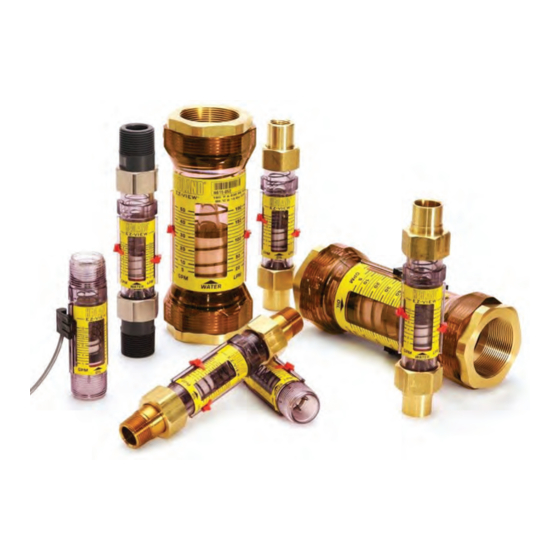
Introduction INTRODUCTION EZ-View® flow meters are rugged, low-cost, direct reading, industrial class flow meters that are simple to install� They can be mounted in any position without costly flow straighteners or other special plumbing� Constructed of high impact thermoplastics, the flow meters offer excellent structural integrity and chemical compatibility with a wide range of industrial chemicals�... - Page 5 Introduction Figure 2: EZ-View Components ID Number Part Description Fittings Bushings O-Ring / Seal Pressure Gauge (Test Kits) | Not Pictured Control Valve (Test Kits) Page 6 VAM-UM-00367-EN-03 October 2019 1.800.561.8187 information@itm.com www. .com...
-
Page 6: Operating Principle
Operating Principle OPERATING PRINCIPLE Hedland® EZ-View flow meters are piston-type variable area flow meters that use a sharp-edged annular orifice, formed between an open-centered piston and a tapered metering cone� The piston is held in the no-flow position at the base of the cone by a precision retention spring�... -
Page 7: Installation
Installation INSTALLATION THIS UNIT SHOULD BE INSTALLED AND SERVICED BY TECHNICALLY QUALIFIED PERSONNEL TRAINED IN MAINTAINING INDUSTRIAL CLASS FLOW INSTRUMENTATION AND PROCESSING EQUIPMENT. READ INSTRUCTIONS THOROUGHLY BEFORE INSTALLING THE UNIT. IF YOU HAVE ANY QUESTIONS REGARDING PRODUCT INSTALLATION OR MAINTENANCE, CALL YOUR LOCAL SUPPLIER FOR MORE INFORMATION. -
Page 8: Piping Plumbing
Installation Piping Plumbing TO AVOID UNNECESSARY PIPE FLEXING THAT COULD CAUSE STRUCTURAL STRESS ON THE FLOW METER BODY, USE INDEPENDENT SUPPORT LOCATED AS NEAR AS POSSIBLE TO THE INLET AND OUTLET OF THE METER TO ISOLATE THE METER FROM THE PIPING SYSTEM. -
Page 9: Mounting Orientation
Installation Mounting Orientation The meter can be installed to operate in any position� Models with 1 in. (25.40 mm) Male NPTF End Connections Pipe Support Plastic Coupling Plastic Coupling Metal Pipe Union Figure 5: 1 in. (25.40 mm) Male NPTF installation 1�... -
Page 10: Models With Pvc Socket Weld End Fittings
Installation Models with PVC Socket Weld End Fittings Union Pipe Support Coupling PVC Pipe Figure 6: PVC socket weld installation 1� Remove the two end fittings from the flow meter� Lubricate the O-rings and install the fittings onto the flow meter� LIQUID PIPE SEALANTS, PVC/CPVC PRIMERS AND PVC/CPVC CEMENTS CONTAIN SOLVENTS THAT ARE NOT COMPATIBLE WITH POLYSULFONE PLASTIC. -
Page 11: Models With Brass Sweat End Fittings
Installation Models with Brass Sweat End Fittings Pipe Support Figure 7: Brass sweat fitting installation 1� Remove both brass fittings from the flow meter inlet and outlet� Remove O-rings from the fittings� 2� Apply solder flux to the flow meter brass fittings and mating pipe surfaces� 3�... -
Page 12: Models With Male, Metal Or Pvc Threaded End Fittings
Installation Models with Male, Metal or PVC Threaded End Fittings Pipe Support Figure 8: Male, metal or PVC threaded end fittings installation 1� Remove both fittings from the flow meter inlet and outlet� Remove the O-rings from the fittings� 2� Apply Teflon® tape to the male pipe thread connections� 3�... -
Page 13: Models With Female, Metal Threaded End Fittings
Installation Models with Female, Metal Threaded End Fittings Pipe Support Metal Pipe Union Figure 9: Female, metal threaded end fittings installation 1� Apply Teflon® tape to the male pipe thread connections� 2� Thread the inlet of the flow meter onto the appropriate pipe connection� Make sure the flow direction arrow on the flow meter corresponds with the system flow direction�... -
Page 14: Flow-Alert Switch Options
Flow-Alert Switch Options FLOW-ALERT SWITCH OPTIONS OTEE: All Flow-Alert switches are magnetically triggered� Switches cannot be added to meters that were not ordered with the switching magnet� Switches and flow meters are purchased separately� Flow-Alert Latching Limit Switch Switch Deadband Contacts Full Scale... -
Page 15: Flow-Alert Reed Limit Switch
Flow-Alert Switch Options Flow-Alert Reed Limit Switch 15 - 25% Of Scale Switch Contacts Full Scale FLOW DIRECTION CAUTION 1. Only use Teflon tape to seal threaded fittings. DO NOT use pipe dope. 2. DO NOT sweat fit adaptor fittings into a system while mounted to the EZ-VIEW meter. -
Page 16: Flow-Alert Switch Installation
Flow-Alert Switch Installation FLOW-ALERT SWITCH INSTALLATION Latching Switch 1� Install one end of the vibration locking kit onto the lpm side of the meter’s serrated rail as shown in Figure 12� 2� Install the switch by placing the adjustment arm over the serrated rail from the inlet end of the 1/2 in�... - Page 17 Flow-Alert Switch Installation 4� Determine which direction the body of the connector should face� See Figure 15� 5� Snap the connector back together, pull the excess wire out of the strain relief, then tighten the strain relief nut� 6� Plug the connector into the switch module and secure with the screw provided� Polarity Pin Figure 15: Polarity pin Latching Switch AC Wiring Configuration...
- Page 18 Flow-Alert Switch Installation AC Conventional Secondary Connections Figure 17 shows a secondary relay with a 115V AC coil integrated with the AC switch module� This combination allows switching of loads up to the rating of the relay contacts� OTEE: Load limited by relay contacts� Fuse Flow Circuit...
-
Page 19: Reed Switch
Flow-Alert Switch Installation Reed Switch Install the switch on the flow meter by placing the adjustment arm over the serrated rail from the inlet end of the 1/2 in� (12 mm), 3/4 in� (19 mm), and 1 in� (25 mm) meters, or the outlet end of the 1-1/2 in�... -
Page 20: Flow-Alert Reed Switch Adjustment
Flow-Alert Switch Installation Flow-Alert Reed Switch Adjustment After the flow meter has been installed and the switch wired, the flow rate at which the switch activates must be adjusted� 1� With the fluid running through the meter, gently move the switch adjustment tab outward until the switch body is free to slide up or down on the serrated rail�... -
Page 21: Maintenance
Maintenance MAINTENANCE EZ-View flow meters are designed to provide many years of service with little or no maintenance requirements� Periodic cleaning may be required� To clean the outside of the meter, use denatured alcohol or mild detergent and warm water� If the inside of the meter becomes stained or particulates get jammed in the meter, use one of the following disassembly procedures: 1/2…1 in. -
Page 22: Fluid Correction Standard Flow Scales
Fluid Correction Standard Flow Scales FLUID CORRECTION STANDARD FLOW SCALES Standard liquid flow scales are calibrated in gpm (Gallons per Minute) and lpm (Liters per Minute) at 0�876 specific gravity for petroleum-based fluids, and 1�0 specific gravity for water and water-based fluids� For field conversion of the standard scale to other fluids, see "Density Effect"... -
Page 23: Fluid Selection Chart
Fluid Correction Standard Flow Scales Fluid Selection Chart Internal Compo- Fittings nents Correction Factor of Specific Standard Scales Fluid Gravity Water Acetic Acid (Air Free) 1�06 0�909 0�971 — Acetone 0�79 1�053 1�125 Alcohol, Butyl (Butanol) 0�83 1�027 1�089 — Alcohol, Ethyl (Ethanol) 0�83 1�027... -
Page 24: Pressure Drop Charts
Pressure Drop Charts PRESSURE DROP CHARTS The pressure drop curves are valid for fluids with density and viscosity similar to factory test fluids� Fluids with higher viscosity than these test fluids yield a higher pressure drop through the flow meter and piping system per a given flow volume� A system must have adequate fluidic horsepower available to move the system fluid at a prescribed rate at a pressure adequate to overcome all pressure reducing devices, including the flow meter�... -
Page 25: Specifications
Specifications SPECIFICATIONS Accuracy ±5% of full scale Repeatability ±1% 325 psi (22�4 bar) Maximum Pressure Rating Meters with PVC fittings subject to normal PVC system ratings 32…250° F (0…121° C) Temperature Range 32…140° F (0…60° C) for meters with PVC fittings NPT ANSI/ASME B1�20�1 Fittings/Threads BSPT ISOR7... -
Page 26: Dimensions
Dimensions DIMENSIONS 1/2 in., 3/4 in. and 1 in. Sizes CAUTION 1. Only use Te on tape to seal threaded ttings. DO NOT use pipe dope. 2. DO NOT sweat t adaptor ttings into a system while mounted to the EZ-VIEW meter. Connection Fitting Flats Model... -
Page 27: 2-1/2 In. And 3 In. Sizes
Control. Manage. Optimize. HEDLAND is a registered trademark of Badger Meter, Inc� Other trademarks appearing in this document are the property of their respective entities� Due to continuous research, product improvements and enhancements, Badger Meter reserves the right to change product or system specifications without notice, except to the extent an outstanding contractual obligation exists�...
Need help?
Do you have a question about the Hedland EZ-View H915 and is the answer not in the manual?
Questions and answers