Advertisement
Quick Links
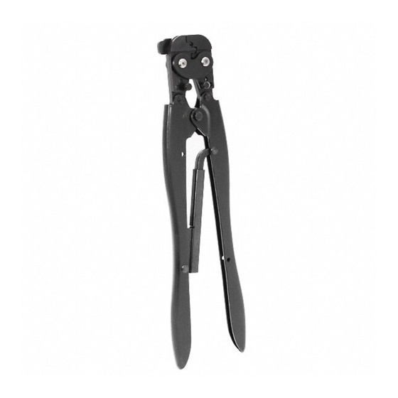
PROPER USE GUIDELINES
Cumulative Trauma Disorders can result from the prolonged use of manually powered hand tools. Hand tools are intended for occasional use
and low volume applications. A wide selection of powered application equipment for extended-use, production operations is available.
Indenter Crimping Jaw
Anvil
Crimping Jaw
Locator
1. INTRODUCTION
Hand Crimping Tools 46673, 46673-1, and 46988 for
STRATO-THERM Terminals are used to crimp high-
temperature and heat-resistant STRATO-THERM
terminals and splices onto wire sizes 22 through 14
AWG.
All dimensions on this document are in metric units
NOTE
[with U.S. customary units in brackets]. Figures and
illustrations are for identification only and are not
i
drawn to scale.
Reasons for reissue of this instruction sheet are
provided in Section 7, REVISION SUMMARY.
2. DESCRIPTION
Each hand tool features an indenter crimping jaw, an
anvil crimping jaw, locator, two insulation crimping
adjustment pins, and a CERTI-CRIMP hand tool
ratchet. The hand tool has the wire size marked on the
BACK side of the tool. The locator positions the
terminal or splice between the crimping jaws. The
©2013 Tyco Electronics Corporation, a TE Connectivity Ltd. Company
All Rights Reserved
*Trademark
TE Connectivity, TE connectivity (logo), and TE (logo) are trademarks. Other logos, product and/or Company names may be trademarks of their respective owners.
Hand Crimping Tools 46673,
46673-1, and 46988 for
STRATO-THERM* Terminals
Wire Size Marking
Figure 1
TOOLING ASSISTANCE CENTER 1-800-722-1111
PRODUCT INFORMATION 1-800-522-6752
Back Side of Tool
CERTI-CRIMP* Hand
Tool Ratchet
Insulation Crimping
Adjustment Pins
insulation crimping adjustment pins are used to
regulate the crimp height of the insulation barrel
sleeve.
The hand tool ratchet assures full crimping of the
terminal. Once engaged, the ratchet will not release
until the tool handles have been FULLY closed. See
Figure 1.
The crimping jaws bottom before the
NOTE
CERTI-CRIMP hand tool ratchet releases. This
design feature ensures maximum electrical and
i
tensile performance of the crimp. Do NOT re-adjust
the ratchet.
3. CRIMPING PROCEDURE
1. Strip wire using the recommended strip-length
dimensions provided in Figure 2.
This controlled document is subject to change.
For latest revision and Regional Customer Service,
visit our website at www.te.com
Instruction Sheet
408-1535
22 AUG 13 Rev S
1 of 6
LOC B
Advertisement

Subscribe to Our Youtube Channel
Related Manuals for TE Connectivity CERTI-CRIMP Series


Summary of Contents for TE Connectivity CERTI-CRIMP Series
- Page 1 PRODUCT INFORMATION 1-800-522-6752 For latest revision and Regional Customer Service, *Trademark visit our website at www.te.com LOC B TE Connectivity, TE connectivity (logo), and TE (logo) are trademarks. Other logos, product and/or Company names may be trademarks of their respective owners.
- Page 2 408-1535 2. To open the crimping jaws, close the tool handles WIRE until the CERTI-CRIMP hand tool ratchet releases. TOOL SIZE INSULATION STRIP Note that the tool handles cannot be opened until (AWG) RANGE LENGTH they are FULLY closed. 2.67-3.56 46673 3.
- Page 3 408-1535 The wire barrel sleeve on high-temperature If the splice cannot be turned around to position the NOTE NOTE terminals and splices is color coded orange. Heat- uncrimped sleeve in the crimping jaws, turn the tool resistant terminals and splices are not color coded. around.
-
Page 4: Maintenance And Inspection Procedure
408-1535 4. Perform a test crimp as described in Section 3, • Tool used in daily production-lubricate daily Step 6. Remove the crimped terminal or splice and • Tool used daily (occasional)-lubricate weekly check the insulation support. Bend the wire back •... -
Page 5: Section 6, Replacement And Repair
408-1535 5.5. Ratchet Inspection The ratchet feature on the hand tools should be checked to ensure that the ratchet does not release NO-GO prematurely, allowing the jaws to open before they have fully bottomed. Obtain a .025 mm [.001 in.] shim Dim. -
Page 6: Revision Summary
• ensure quality and reliability of the tool. Order Added new information to table in Figure 2 replacement parts through your TE Connectivity Representative, or call 1-800-526-5142, or send a facsimile of your purchase order to 1-717-986-7605, or write to:...
Need help?
Do you have a question about the CERTI-CRIMP Series and is the answer not in the manual?
Questions and answers