Table of Contents
Advertisement
Quick Links
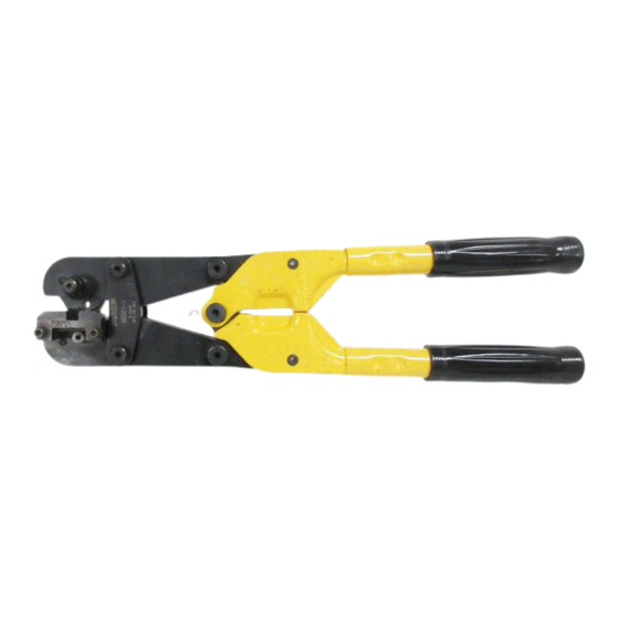
Stationary
Die (Nest)
Anvil Die
Hold-Down
Device and
Contact Locator
Front of
Tool
Figure 1
1. INTRODUCTION
ROTA-CRIMP Crimping Tool 68321-1 (shown in
Figure 1) is used to crimp Series 75 Power Lock
Contact 53880-4 onto solid or stranded wire sizes 10,
8, or 6 AWG. Read these instructions thoroughly
before using the tool.
Dimensions in this instruction sheet are in
NOTE
millimeters [with inches in brackets]. Figures and
illustrations are for reference only and are not
i
drawn to scale.
Reasons for reissue of this instruction sheet are
provided in Section 7, REVISION SUMMARY.
2. DESCRIPTION
The FRONT of the tool, into which the contact is
inserted, can be identified by the tool part number on
the link. The tool features a stationary die (6.35 mm
[.250 in.] wide F crimp nest), rotatable anvil die with
three settings, hold-down device, and contact locator.
The anvil must be set to the wire size being used. The
applicable wire size is stamped on the base of the
anvil die. When closed, the dies form one crimping
chamber.
©2012 Tyco Electronics Corporation, a TE Connectivity Ltd. company
All Rights Reserved
*Trademark
TE Connectivity, TE connectivity (logo), and TE (logo) are trademarks. Other logos, product and/or company names may be trademarks of their respective owners.
ROTA-CRIMP*
Crimping Tool
68321-1
The hold-down device and contact locator are
mounted on a metal strip. The metal strip must be
Locator Pin
adjusted to accommodate the contact position during
Indexing Pin
the crimping process.
3. CRIMPING PROCEDURE
Wire Size
Refer to Figure 2, and strip the wire to within the
Marking
dimensions shown.
Proceed as follows:
TOOLING ASSISTANCE CENTER 1-800-722-1111
PRODUCT INFORMATION 1-800-522-6752
DO NOT use wires with missing or nicked
CAUTION
conductor strands.
!
Series 75 Power Lock Contact
Transition
Area
Strip Length
CONTACT
WIRE SIZE (AWG)
53880-4
10, 8, 6
Figure 2
1. Open the tool head. Make sure that the anvil die
is locked in position and that the locator pin is visible
as shown in Figure 1. It is not necessary at this time
to set the anvil die to a specific wire size.
2. Place a sample contact in the nest of the
stationary die as shown in Figure 3. The open end
of the wire barrel must be aligned in the nest.
3. Loosen the two screws securing the hold-down
device and contact locator, and position the contact
locator over the contact tongue as shown in
Figure 3. Do not re-tighten the screws at this time.
The hold-down device and contact locator must be
NOTE
properly adjusted so that the contact will remain
aligned during the crimping process.
i
4. Slowly close the tool head, making sure the
contact remains properly positioned in the nest. If
the contact is cocked or otherwise out of line, re-
align it before proceeding. The contact should
remain in the nest as shown in Figure 3. DO NOT
deform the wire barrel.
This controlled document is subject to change.
For latest revision and Regional Customer Service,
visit our website at www.te.com
Instruction Sheet
408-2681
13 APR 12 Rev C
Wire Barrel
WIRE STRIP
LENGTH
7.95-9.53
[.313-.375]
1 of 5
Advertisement
Table of Contents

Related Manuals for TE Connectivity 68321-1


Summary of Contents for TE Connectivity 68321-1
- Page 1 All Rights Reserved PRODUCT INFORMATION 1-800-522-6752 For latest revision and Regional Customer Service, *Trademark visit our website at www.te.com TE Connectivity, TE connectivity (logo), and TE (logo) are trademarks. Other logos, product and/or company names may be trademarks of their respective owners.
- Page 2 408-2681 8. Close tool head just enough to retain the contact; Wire Conductor Flush then insert the wire into the wire barrel, making sure with or Recessed the wire does not extend beyond the wire barrel. Slightly in Wire Barrel See Figure 5.
- Page 3 408-2681 B. Handle Adjustment 2. Make sure the proper retaining pins are in place and secured with the proper retaining rings. The handle adjustment should be checked to ensure 3. Make certain all pins, pivot points, and bearing that the dies are bottoming properly. The handle surfaces are protected with a THIN coat of any good adjustment feature is provided to compensate for SAE 20 motor oil.
- Page 4 3. Close handles until dies are bottomed but not parts is necessary. Parts other than those listed should under pressure. be replaced by TE Connectivity to ensure quality and 4. Insert GO element into the crimping chamber; but reliability. Order replacement parts through your do not force it.
- Page 5 408-2681 7. REVISION SUMMARY CUSTOMER SERVICE (038-035) • TYCO ELECTRONICS CORPORATION Updated document to corporate requirements PO BOX 3608 • Changed dimension information in Figure 9 HARRISBURG PA 17105-3608 • Changed table in Figure 9 For repair service, contact a TE Representative at 1-800-526-5136.
Need help?
Do you have a question about the 68321-1 and is the answer not in the manual?
Questions and answers