
Subscribe to Our Youtube Channel
Related Manuals for TE Connectivity IDC Hand tool RAST 2.5


Summary of Contents for TE Connectivity IDC Hand tool RAST 2.5
- Page 1 Operation Manual IDC Hand tool RAST 2.5 and 5 Customer Manual Nr.: 412-94126-1 Rev. A Customer Manual PN: 744015-5 Language: en (Translation of the original German version)
- Page 2 IDC Hand tool RAST 2.5 and 5 The data specified above only serve to describe the product. No statements concerning a certain condition or suitability for a certain application can be derived from our information. The information given does not release the user from the obligation of own judgment and verification.
-
Page 3: Table Of Contents
IDC Hand tool RAST 2.5 and 5 General information ....................4 Copyrights, industrial property rights......................4 Using the operation manual..................5 Abbreviations used..........................5 General safety instructions ..................6 Intended use............................6 Improper use ............................6 Reasonably foreseeable misuse ......................6 Qualification of personnel........................7 Safety instructions in this document.......................7 Adhere to the following instructions .......................8... - Page 4 IDC Hand tool RAST 2.5 and 5 Using the table mounting..................18 Preparation of the connector ................... 20 Making a connection....................23 AMP DUOPLUG 2.5 Mark II.........................23 AMP DUOPLUG 2.5 Power .........................29 AMP multifitting Mark II ........................34 AMP MONO-SHAPE Mark II........................40 AMP MONO-SHAPE Mark I.........................46...
-
Page 5: General Information
It may not be reproduced or given to third parties without its consent. This manual is exclusively meant for the carrier of the „IDC Hand tool RAST 2.5 and 5“ (in further course called “IDC Hand tool”) and its personnel for internal use only. -
Page 6: Using The Operation Manual
Each person entrusted with the job of operating the IDC Hand tool, must be familiar with the opera- tion manual and strictly observe the instructions therein. TE Connectivity Ltd. decline to accept any liability for damages that are incurred due to the fact that the instructions in the operation manual have been disregarded. -
Page 7: General Safety Instructions
Cumulative Trauma Disorders can result from a prolonged use of manually powered hand tools. TE Connectivity Ltd. hand tools are intended for occasional use and low volume applications. For extended use or production operations TE Connectivity Ltd. offers a wide selection of powered application equipment. -
Page 8: Qualification Of Personnel
IDC Hand tool RAST 2.5 and 5 Qualification of personnel In order to ensure operating safety, these activities may therefore only be carried out by qualified technical personnel or an instructed person under the direction and supervision of qualified personnel. -
Page 9: Adhere To The Following Instructions
For environmentally friendly disposal please observe the notes in section 11 ”Disposal”. Obligations of the operator The operator of the TE Connectivity Ltd. products is bound to provide for personnel training on a regular basis regarding the following subjects: Observation and use of the operating instructions and the legal regulations Intended use and operation of the IDC hand tool. -
Page 10: Scope Of Delivery
IDC Hand tool RAST 2.5 and 5 Scope of delivery The scope of delivery includes following parts: 1 transport case containing misc. tools (section 6.1 ”Components overview”) 1 operating manual ©2009 Tyco Electronics Corporation, Harrisburg, PA 9/ 55 Operation Manual... -
Page 11: Product Description
IDC Hand tool RAST 2.5 and 5 Product description Depending on the application the IDC Hand tool has been designed to apply connectors (according to the TE specification) (section 5 „Product description“) with wires using Insulation Displacement Technique (RAST 2.5 and 5). -
Page 12: Content Of Case
IDC Hand tool RAST 2.5 and 5 Content of case Components overview Fig. 1: Components overview 1 Set of socket head wrenches 5 Side cutter (latching rib) 2 IDC- RAST Hand tool with 6 End cutter (Keying rib) tool head and adapter... -
Page 13: Construction Of The Hand Tool
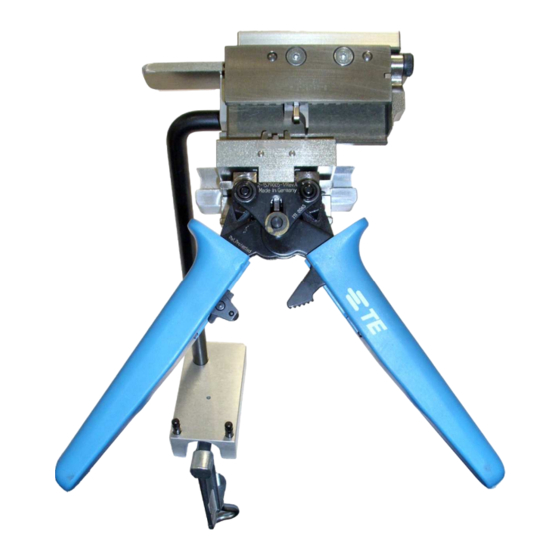
IDC Hand tool RAST 2.5 and 5 Construction of the hand tool The Hand tool consists of the movable handle with the guidance and the stuffer (4), the adapter (5), the table mounting consists of the table clamp piece (2) and the bracket (3) as well as the tool head consists of the holding fixture with connector clamping (1). -
Page 14: Construction Of The Tool Heads
IDC Hand tool RAST 2.5 and 5 Construction of the tool heads 6.3.1 AMP DUOPLUG 2.5 Mark II Fig. 3: Tool Head Design AMP DUOPLUG 2.5 Mark II Chamber’s exterior fixation, static Stuffer Press bar for connector’s fixation Tool head / guidance incl. -
Page 15: Amp Duoplug 2.5 Power
IDC Hand tool RAST 2.5 and 5 6.3.2 AMP DUOPLUG 2.5 Power Fig. 4: Head Design AMP DUOPLUG 2.5 Power Tool head / Tool head / holding fixture incl. guidance incl. stuffer unit connector clamping Stuffer Press bar for connector’s fixation Chamber’s exterior fixation,... -
Page 16: Amp Multifitting Mark Ii
IDC Hand tool RAST 2.5 and 5 6.3.3 AMP multifitting Mark II Fig. 5: Tool Head Design AMP multifitting Mark II Locking screw Chamber fixation Tool head / holding fixture incl. Forked sleeve for connector clamping Chamber fixation Chamber’s exterior fixation,... -
Page 17: Amp Mono-Shape Mark Ii
IDC Hand tool RAST 2.5 and 5 6.3.4 AMP MONO-SHAPE Mark II Fig. 6: Tool Head Design AMP MONO-SHAPE Mark II Locking screw Chamber fixation Tool head / holding fixture incl. Forked sleeve for connector clamping Chamber fixation Chamber’s exterior fixation,... -
Page 18: Amp Mono-Shape Mark I
IDC Hand tool RAST 2.5 and 5 6.3.5 AMP MONO-SHAPE Mark I Fig. 7: Tool Head Design AMP MONO-SHAPE Mark I Locking screw Gauge piece resp. snap-fitting of the connector’s width Tool head / holding fixture incl. Chamber fixation connector clamping... -
Page 19: Using The Table Mounting
IDC Hand tool RAST 2.5 and 5 Using the table mounting For assistance the hand tool can be fixed on a work table, so you can use both the hands to work. Attach the table mounting (1 / see page 11) to an appropriate place. - Page 20 IDC Hand tool RAST 2.5 and 5 Fix the bracket in the requested position by using the two clamp screw of the adapter(arrow). Fig. 10: Fixation of the bracket The complete hand tool is exemplary displayed in Fig. 11. Fig. 11: Complete hand tool with table mounting ©2009 Tyco Electronics Corporation, Harrisburg, PA...
-
Page 21: Preparation Of The Connector
IDC Hand tool RAST 2.5 and 5 Preparation of the connector The preparation of the connector will be shown exemplarily by using the AMP multifitting Mark II and applies analogously to all similar products listed in 5.1 „Handled Connectors“. The connectors will be delivered exclusively linked on strip. - Page 22 IDC Hand tool RAST 2.5 and 5 Pull up the connector to be separated against the cover of the fitting connector. By slightly tilting and a sufficient force both the latching ribs gets released and disconnect the connector. Strictly observe not to damage the connectors when separating it! Separate the connector’s cover in consideration of its specification by moving it back and forth or...
- Page 23 IDC Hand tool RAST 2.5 and 5 Remove the keying ribs according to the respective specification by using the end cutter (PN 539601-3). Fig. 16: Cutting-off keying ribs Ready-to-use connector: Fig. 17: Ready-to-use connector ©2009 Tyco Electronics Corporation, Harrisburg, PA...
-
Page 24: Making A Connection
IDC Hand tool RAST 2.5 and 5 Making a connection AMP DUOPLUG 2.5 Mark II Insert the prepared connector into the check rail between the stuffer unit and holding fixture incl. connector clamping. Fig. 18: Inserting connector Press down the clamping bar (1) for an easier handling. - Page 25 IDC Hand tool RAST 2.5 and 5 Move the transport unit to positioning the connector’s IDC contacts straight to the stuffer. Fig. 20: Positioning of the connector Make sure that the transport unit is explicit engaged. An attempt of clamping using an incorrect engaged transport unit will damage the stuffer! Move the forked sleeve (1) to the left (arrow), so that the green marker (2) appears.
- Page 26 IDC Hand tool RAST 2.5 and 5 Feed the end of the insulted wire to the IDC contact, so the wire rests flush with the bottom face (arrow) of the connector. Check the correct position of the wire. The gripper still remains open.
- Page 27 IDC Hand tool RAST 2.5 and 5 The stuffer heads for the IDC contact. The chamber’s exterior fixation protects the chamber’s side walls against unintended deformation. The stuffer inserts the wire into the IDC contact, where the wire is insulated and fixed.
- Page 28 IDC Hand tool RAST 2.5 and 5 Move the forked sleeve (1) to the right (arrow), so that the red marker (2) appears. This lifts out the chamber fixation from its functional position. At once the gripper is getting blocked against pinching.
- Page 29 IDC Hand tool RAST 2.5 and 5 Put the cover onto the connector considering the respective specifications and press it in. The cover has to be in the correct position. Use an appropriate tool if applicable. Fig. 27: Pressing in the cap ©2009 Tyco Electronics Corporation, Harrisburg, PA...
-
Page 30: Amp Duoplug 2.5 Power
IDC Hand tool RAST 2.5 and 5 AMP DUOPLUG 2.5 Power Insert the prepared connector into the check rail between the stuffer unit and the transport unit. Fig. 28: Inserting connector Press down the clamping bar (1) for an easier handling. - Page 31 IDC Hand tool RAST 2.5 and 5 Move the transport unit to positioning the connector’s IDC contacts straight to the stuffer. Fig. 30: Positioning of stuffer Make sure that the transport unit is explicit engaged. An attempt of clamping using an incorrect engaged transport unit will damage the stuffer.
- Page 32 IDC Hand tool RAST 2.5 and 5 Pinch the gripper. Fig. 32: Pinching the gripper The stuffer and the chamber fixation head for the IDC contact. The stuffer inserts the wire into the IDC contact, where the wire is insulated and fixed.
- Page 33 IDC Hand tool RAST 2.5 and 5 Loosening the gripper. Fig. 34: Loosening the gripper Repeat the positioning of the stuffer below the insulation displacement termination to be handled by means of the guidance, the feeding of the insulated wire as well as the pinching and loosening of the gripper for all chambers to be provided with a wire.
- Page 34 IDC Hand tool RAST 2.5 and 5 Put the cover onto the connector considering the respective specifications and press it in. The cover has to be in the correct position. Use an appropriate tool if applicable. Fig. 36: Pressing in the cap ©2009 Tyco Electronics Corporation, Harrisburg, PA...
-
Page 35: Amp Multifitting Mark Ii
IDC Hand tool RAST 2.5 and 5 AMP multifitting Mark II Fold up the foldaway fixation to insert the connector into the guidance. Insert the prepared connector into the check rail between the stuffer unit and the transport unit. Fig. 37: Inserting connector Fold down the foldaway fixation. - Page 36 IDC Hand tool RAST 2.5 and 5 Make sure that the chamber fixations are in the right position. Misplaced chamber fixations will cause a negative impact on the quality of contacting! Move the transport unit to positioning the connector’s IDC contacts straight to the stuffer.
- Page 37 IDC Hand tool RAST 2.5 and 5 Make sure that the green marker appears. If it is not visible, the gripper is blocked against pinching! Feed the end of the insulted wire to the IDC contact, so the wire rests flush with the bottom face (arrow) of the connector.
- Page 38 IDC Hand tool RAST 2.5 and 5 The stuffer heads for the IDC contact. The chamber’s exterior fixation protects the chamber’s side walls against unintended deformation. The stuffer inserts the wire into the IDC contact, where the wire is insulated and fixed.
- Page 39 IDC Hand tool RAST 2.5 and 5 Move the forked sleeve (1) to the right (arrow), so that the red marker (2) appears. This lifts out the chamber fixation from its functional position. At once the gripper is getting blocked against pinching.
- Page 40 IDC Hand tool RAST 2.5 and 5 Put the cover onto the connector considering the respective specifications and press it in. The cover has to be in the correct position. Use an appropriate tool if applicable. Fig. 46: Pressing in the cap ©2009 Tyco Electronics Corporation, Harrisburg, PA...
-
Page 41: Amp Mono-Shape Mark Ii
IDC Hand tool RAST 2.5 and 5 AMP MONO-SHAPE Mark II Fold up the foldaway fixation to insert the connector into the guidance. Insert the prepared connector into the check rail between the stuffer unit and the transport unit. Fig. 47: Inserting connector Fold down the foldaway fixation (1). - Page 42 IDC Hand tool RAST 2.5 and 5 Make sure that the chamber fixations are in the right position. Misplaced chamber fixations will cause a negative impact on the quality of contacting! Move the transport unit to positioning the connector’s IDC contacts straight to the stuffer.
- Page 43 IDC Hand tool RAST 2.5 and 5 Make sure that the green marker appears. If it is not visible, the gripper is blocked against pinching! Feed the end of the insulted wire to the IDC contact, so the wire rests flush with the bottom face (arrow) of the connector.
- Page 44 IDC Hand tool RAST 2.5 and 5 The stuffer heads for the IDC contact. The chamber’s exterior fixation protects the chamber’s side walls against unintended deformation. The stuffer inserts the wire into the IDC contact, where the wire is insulated and fixed.
- Page 45 IDC Hand tool RAST 2.5 and 5 Move the forked sleeve (1) to the right (arrow), so that the red marker (2) appears. This lifts out the chamber fixation from its functional position. At once the gripper is getting blocked against pinching.
- Page 46 IDC Hand tool RAST 2.5 and 5 Put the cover onto the connector considering the respective specifications and press it in. The cover has to be in the correct position. Use an appropriate tool if applicable. Fig. 56: Pressing in the cap ©2009 Tyco Electronics Corporation, Harrisburg, PA...
-
Page 47: Amp Mono-Shape Mark I
IDC Hand tool RAST 2.5 and 5 AMP MONO-SHAPE Mark I This tool head can handle to types of connectors: Type „TAB“ according to specification 114-20016 and Type „PC“ according to specification 114- 20018. Handling type “PC” a compensation bar (arrow) has to be adopted into the tool head to compensate the “TAB”-Type’s different stack height. - Page 48 IDC Hand tool RAST 2.5 and 5 Make sure that the chamber fixations are in the right position. Misplaced chamber fixations will cause a negative impact on the quality of contacting! Move the transport unit to positioning the connector’s IDC contacts straight to the stuffer.
- Page 49 IDC Hand tool RAST 2.5 and 5 Make sure that the green marker appears. If it is not visible, the gripper is blocked against pinching! Feed the end of the insulted wire to the IDC contact, so the wire rests flush with the bottom face (arrow) of the connector.
- Page 50 IDC Hand tool RAST 2.5 and 5 The stuffer heads for the IDC contact. The chamber’s exterior fixation protects the chamber’s side walls against unintended deformation. The stuffer inserts the wire into the IDC contact, where the wire is insulated and fixed.
- Page 51 IDC Hand tool RAST 2.5 and 5 Move the forked sleeve (1) to the right (arrow), so that the red marker (2) appears. This lifts out the chamber fixation from its functional position. At once the gripper is getting blocked against pinching.
- Page 52 IDC Hand tool RAST 2.5 and 5 Put the cover onto the connector considering the respective specifications and press it in. The cover has to be in the correct position. Use an appropriate tool if applicable. Fig. 66: Pressing in the cap ©2009 Tyco Electronics Corporation, Harrisburg, PA...
-
Page 53: Maintenance And Repair
IDC Hand tool RAST 2.5 and 5 Maintenance and Repair 10.1 Daily Maintenance For the daily maintenance following steps has to be taken by the responsible operator: Clean up the tool from dust, humidity and other residues by means of a clean, soft scrubber or a lint- free cloth never use rigorous or abrasive mediums to avoid damaging the tool. -
Page 54: Disposal
IDC Hand tool RAST 2.5 and 5 Disposal Careless disposal of the applicator lead to pollution of the environment. In case of disposal, please send the hand tool and ist components back to the address specified in section 13.1 “Contact information”. -
Page 55: Troubleshooting
IDC Hand tool RAST 2.5 and 5 Troubleshooting If the engagement of the holding fixture incl. connector clamping is not positioned correctly, the stuffer will drive against the connector. Due to that the connector will get damaged (arrow). Fig. 67: Damaging of connector If the gripper gets jammed you must not keep on pushing the gripper in no way but use the extrac- tion mechanism (arrow). -
Page 56: Appendix
IDC Hand tool RAST 2.5 and 5 Appendix 13.1 Contact information TE Connectivity c/o Schenck Technologie- und Industriepark GmbH Landwehrstr. 55 / Gebäude 83 64293 Darmstadt Field Service EMEA@te.com GATD Kundendienst-Hotline: +49-6151-607-1518 ©2009 Tyco Electronics Corporation, Harrisburg, PA 55/ 55...
Need help?
Do you have a question about the IDC Hand tool RAST 2.5 and is the answer not in the manual?
Questions and answers