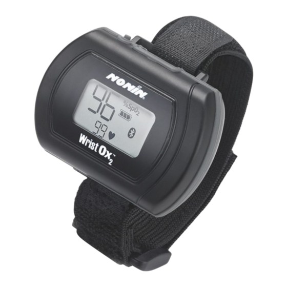
Nonin WristOx2 3150 Technical Information
Bluetooth wrist-worn pulse oximeter
Hide thumbs
Also See for WristOx2 3150:
- Operator's manual (51 pages) ,
- Operator's manual (699 pages) ,
- Operator's manual (55 pages)
Table of Contents
Advertisement
Quick Links
TM
WristOx
2
®
Model 3150 Bluetooth
Wrist-Worn Pulse Oximeter
OEM Specification and Technical Information
®
Nonin
Medical, Inc.
13700 1st Avenue North
Plymouth, Minnesota 55441-5443
USA
+1 763-553-9968
800-356-8874 (USA and Canada)
Fax +1 763-553-7807
E-mail: info@nonin.com
www.nonin.com
© 2010 Nonin Medical, Inc.
7970-000-01
Advertisement
Table of Contents

Subscribe to Our Youtube Channel
Related Manuals for Nonin WristOx2 3150


Summary of Contents for Nonin WristOx2 3150
- Page 1 Model 3150 Bluetooth Wrist-Worn Pulse Oximeter OEM Specification and Technical Information ® Nonin Medical, Inc. 13700 1st Avenue North Plymouth, Minnesota 55441-5443 +1 763-553-9968 800-356-8874 (USA and Canada) Fax +1 763-553-7807 E-mail: info@nonin.com www.nonin.com © 2010 Nonin Medical, Inc. 7970-000-01...
-
Page 2: Table Of Contents
Contents Specifications..........................1 ® Model 3150 Bluetooth Profiles....................4 Serial Port Profile (SPP)........................4 Health Device Profile (HDP)........................5 Establishing a Bluetooth Connection..................5 Initial Bluetooth Connection Process ....................5 Connection using One Bluetooth Channel .................... 5 Connection Using Two Bluetooth Channels – DF13 with ATR Enabled..........7 Operation Modes........................8 Cable .............................. - Page 3 Regulatory Information......................38 Declaration of Conformity with FCC and Canadian Ministry of Health Rules for Electromagnetic Compatibility ............................ 38 Federal Communications Commission (FCC) Notice ................. 38 Using the Model 3150 ......................39 Guide to Symbols on the Module ......................39 Manufacturer’s Declaration ....................40 Testing Summary........................43 Accuracy Testing ........................
-
Page 4: Specifications
Specifications Oxygen Saturation Range (SpO 0 % to 100 % Pulse Rate Range: 18 to 321 beats per minute (BPM) Display Features: 3-digit numeric Pulse Rate: 3-digit numeric Pulse strength bar graph: 9 levels Battery Status: 4 levels (full, half, low, critical) Indicators: Sensor Fault, Bluetooth connectivity, SmartPoint, Pulse Signal... - Page 5 Measurement Wavelengths and Output Power*: Red: 660 nanometers @ 0.8 mW maximum average ® Infrared (using Nonin PureLight Sensor): 910 nanometers @ 1.2 mW maximum average Internal Power: Battery: Two 1.5 volt AAA alkaline batteries Operating Life -- Bluetooth OFF:...
- Page 6 Dimensions (without strap and sensor): 56 mm x 74 mm x 20 mm (H x W x D) (2.20 in. x 2.91 in. x 0.79 in.) Memory: Type: Non-volatile Capacity: 1,080 hours (4 second data storage rate) 540 hours (2 second data storage rate) 270 hours (1 second data storage rate) Classification per IEC 60601-1 / CAN/CSA-C22.2 No.
-
Page 7: Model 3150 Bluetooth Profiles
® Model 3150 Bluetooth Profiles The 3150 supports both the Serial Port Profile (SPP) and Health Device Profile (HDP). These two profiles are available through the Bluetooth connection. The default communication profile is SPP. If the host device uses the HDP, the 3150 automatically switches to the HDP mode. Figure 1. -
Page 8: Health Device Profile (Hdp)
Health Device Profile (HDP) When the host device uses HDP, the 3150 automatically switches to the HDP Bluetooth mode (Continua). This Bluetooth profile defines a connection for qualified Healthcare and Fitness devices. These devices are called Source and Sink devices. Source devices include pulse oximeters (such as the 3150), weight scales, glucose meters, thermometers and blood pressure monitors. -
Page 9: Figure 2. Data Formats 1, 2, 7, 8, And Df13* Connection Diagram
The 3150 will be discoverable when not paired to an existing master. Make sure any previous master devices are off. Once your device pairs and establishes the Bluetooth connection with the 3150, the 3150 will automatically send continuous data to your device as defined in the Serial Port Profile (SPP) Data Format Definition sections for data formats 2, 7, and 8. -
Page 10: Connection Using Two Bluetooth Channels - Df13 With Atr Enabled
Connection Using Two Bluetooth Channels – DF13 with ATR Enabled When the 3150 device is configured to send Serial Data Format 13 and the ATR feature is enabled, your host device must have two Bluetooth channels. Once the 3150 is powered on, the master device must pair and connect with it. -
Page 11: Operation Modes
Operation Modes The 3150, has three operation modes: Cable, Standby, and On. Cable The device is in Cable mode when it is connected to a PC using the USB interface cable. While in Cable mode, the device does not collect or save data and the Bluetooth radio is off. Standby When the device is in Standby mode, the screen is blank and the device appears to be off. -
Page 12: Sensor Activation Mode
Sensor Activation Mode Sensor Activation mode may be selected by sending the configuration command. In this mode, the device turns on when the activation switch is pressed or when the sensor is disconnected and reconnected. This mode is useful when using a sensor that is not easily removed from the sensor site (e.g., disposable or wrap sensor). -
Page 13: Command Protocols
Command Protocols The 3150 features two levels of commands. The Level 1 commands are intended for real-time operation and do not interrupt patient recording. The Level 2 commands are intended for use when not recording real-time patient measurements, for example when retrieving recorded data using the memory playback command. -
Page 14: Set Data Format And Activation
Set Data Format and Activation Serial Data formats 1, 2, 7, and 8 and one of two activation modes can be selected by sending a Level 1 Configuration command to the 3150 device after the Bluetooth connection is established. If no configuration command is received within 5 seconds after a Bluetooth connection is established, the 3150 will operate and send data based on the last saved configuration settings. - Page 15 Set Operation for Continuous Data Formats Specific to Data Formats 1, 2, 7, and 8, to select the Data Format, Activation, and Bluetooth, send the 3150 the following 8 byte command string: Byte 1 Byte 2 Byte 3 Byte 4 Byte 5 Byte 6 Byte 7...
-
Page 16: Date And Time Settings
Date and Time Settings The host device can set and get the date and time from the 3150. The date and time must conform to the ranges defined below. The date and time will be lost when loss of power is greater than 30 seconds. Name Decimal Range YY (year) -
Page 17: Get Serial Number From 3150
Get Serial Number from 3150 To retrieve the serial number from the 3150, the host must send a 6 byte command: Byte 1 Byte 2 Byte 3 Byte 4 Byte 5 Byte 6 Start (STX) Op Code Data size ID Code Checksum End(ETX) 0x02... -
Page 18: Level 2 Commands - Computer Mode
Level 2 Commands – Computer Mode The Level 2 protocol commands allow the 3150 to be configured for patient recording and memory playback purposes. A new patient record is stored in the non-volatile memory when the record is at least one minute in length. -
Page 19: Table 2. Configuration Sector Parameters
Table 2. Configuration Sector Parameters Byte Description Length Format Reserved Bluetooth Enable Char ASCII Activation Option Char ASCII Patient Data Storage Rate Char ASCII Display Option Char ASCII 5 through 14 Programmed start time 1 Char ASCII (YYMMDDhhmm) 15 through 24 Programmed stop time 1 Char ASCII 25 through 34... - Page 20 Activation Option The Activation Option determines how a device turns on and off. The settings are: Sensor Connect Activation = 1 Programmed Time On/Off = 2 Spot Check Activation = 3 (factory ship default) Valid ASCII Settings: 1, 2, 3 Settings outside of the defined valid settings will cause the entire sector write to be discarded.
- Page 21 Programmed Start and Stop Times The 3150 features three programmable start and stop time pairs. When using the sector write command, you must program a total of six programmable time values. If the programmable time period is not used, simply program these time values with a valid date and time, which can be in the past or future. Each time setting requires the time to be in the following format.
-
Page 22: Get Configuration Sector
Checksum The last two bytes of the configuration section contain the lower 16 bits of the sum of bytes 0 through 133. Checksum (2 LS bytes of sum of bytes 0 to 133) Binary Get Configuration Sector The current configuration sector can be read by sending the get configuration sector command: CFG?<CR><LF>... -
Page 23: Memory Playback Command
Memory Playback Command With the memory playback command, the 3150 will send the contents of the stored patient data beginning with the newest record and ending with the oldest record. To initiate the memory playback, send the following command: MPB?<CR><LF> Response: After the command is received, the 3150 will send a <ACK>... -
Page 24: Serial Data Format Definition (Spp Profile)
Serial data format #13 – Single point spot-check meaurement is sent after the SmartPoint Algorithm completes. Store and forward capability. Serial data formats 2, 7, 8, and 13 feature Nonin’s SmartPoint Technology. The SmartPoint algorithm automatically determines when a high quality measurement is present. - Page 25 Packet Description A frame consists of 5 bytes; a packet consists of 25 frames. Three packets (75 frames) are transmitted each second. Packet Frame Byte 1 Byte 2 Byte 3 Byte 4 Byte 5 STATUS PLETH HR MSB STATUS PLETH HR LSB STATUS PLETH...
- Page 26 Byte 1 – START BYTE Always set to a 01 value. Byte 2 – STATUS BYTE This byte provides status information at a rate of 1/75 of second. Range: 128 to 255 Byte 2 - Status BIT7 BIT6 BIT5 BIT4 BIT3 BIT2 BIT1...
- Page 27 Byte 3 – PLETH BYTE This byte consists of an 8 bit plethysmographic waveform (pulse waveform). The pulse oximeter infra-red signal is filtered and then compressed into an 8 bit value. The compression provides good detail for low to large pulse signals. For uncompressed waveform refer to serial data format #7. Range: to 255 Byte 4 –...
- Page 28 Display Mode - Formatted for Display Purposes: These values are formatted for display purposes and are updated every 1.5 seconds. When the device is removed from the finger, the last SpO and pulse rate reading will be reported for 10 seconds before changing to the missing data value.
-
Page 29: Serial Data Format #7 Definition
Serial Data Format #7 Definition This data format provides the same information as serial data format #2, except that the waveform value provides the full resolution of 16-bits instead of 8-bits. It is recommended for applications where a high resolution waveform is desired. Packet Description A frame consists of 5 bytes;... - Page 30 Byte 1 – STATUS BYTE This byte provides status information at a rate of 1/75 of a second. Range: 128 to 255 Byte 1 - Status BIT7 BIT6 BIT5 BIT4 BIT3 BIT2 BIT1 BIT0 YPRF ARTF SNSF SYNC RPRF GPRF Note: Bit 7 is always set.
- Page 31 Byte 2 & 3 – PLETH BYTE These two bytes consist of a 16 bit plethysmographic waveform (pulse waveform). Range: 0 to 65535 (MSB:LSB ) Byte 2 = MSB Pulse Waveform Byte 3 = LSB Pulse Waveform Pulse waveform value = (Byte 2 decimal value * 256) + Byte 3 decimal value Byte 4 –...
- Page 32 Display Mode - Formatted for Display Purposes: These values are formatted for display purposes and are updated every 1.5 seconds. When the device is removed from the finger the last SpO and Pulse Rate reading will be reported for 10 seconds before changing to the missing data value.
-
Page 33: Serial Data Format #8 Definition
Serial Data Format #8 Definition This data format provides continuous data transmission of a 4 byte data packet sent once per second. The data packet includes real-time data including: SpO and pulse rate formatted for display, status of the measurement, and status of the battery. Packet Description Four bytes of data are transmitted once per second. -
Page 34: Serial Data Format #13 Definition
The SpO and pulse rate values are formatted for display purposes and are updated every 1.5 seconds. When the device is removed from the finger the last SpO and Pulse Rate reading will be reported for 10 seconds before changing to the missing data value. During this 10-second period, the sensor alarm bit (SNSA) is set, indicating that the finger has been removed. - Page 35 Packet Description The serial data format #13 packet includes 6 bytes of header information, a minimum of 14 bytes of spot- check data, and 2 bytes of footer information. To determine the total length for the expandable spot-check data, the host must capture the data length from bytes 5 and 6 of the header. With the minimum data length of 14, the data length defined in bytes 5 and 6 will be (0x00) (0x0E) (14 bytes decimal).
- Page 36 The following are all active high: SPA: SmartPoint Algorithm High quality SmartPoint measurement NOMS: No Measurement No measurement for SpO or pulse rate MEM: From Memory Stored measurement from memory LOW BAT: Low Battery condition Low batteries. Replace batteries as soon as possible. Reserved Reserved for future use 16-Bit HR Format:...
- Page 37 Optional Data The following data is available when the expansion option is set to Enabled (see Selecting Data Format in Command Protocols section). Note: This is optional data, the decision whether or not to include it needs to be selected by the configuring application.
-
Page 38: Indications For Use
EMC, and all equipment must be installed and put into service according to the EMC information specified in this manual. Only use Nonin-branded sensors with a length of 1 meter or less. Accuracy may degrade if sensor cable is over 1 meter in length. Using the sensor cable adapter does not affect accuracy. -
Page 39: Cautions
If you are unsure how to reach your distributor, please call Nonin for your distributor’s contact information. This device is designed to determine the percentage of arterial oxygen saturation of functional hemoglobin. - Page 40 Cautions To avoid the risk of confusing or misinterpreting patient data when transmitting data via Bluetooth, verify the device is paired with the correct display unit. The pulse oximeter may not work when circulation is reduced. Warm or rub the finger or reposition the sensor.
-
Page 41: Regulatory Information
Declaration of Conformity with FCC and Canadian Ministry of Health Rules for Electromagnetic Compatibility Nonin Medical, Inc., of 13700 1st Avenue North, Plymouth, Minnesota, 55441, declares under its sole responsibility that Model 3150, to which this declaration relates, comply with part 15 of the FCC Rules. -
Page 42: Using The Model 3150
Using the Model 3150 Guide to Symbols on the Module Symbol Description Caution! Consult Instructions for Use. Authorized Representative in the European Community CE Marking indicating conformance to EC directive No. 93/42/EEC concerning medical 0123 devices. Type BF Applied Part (Patient isolation from electrical shock). No alarms Indicates separate collection for electrical and electronic equipment (WEEE). -
Page 43: Manufacturer's Declaration
Manufacturer’s Declaration See the following tables for specific information regarding this module’s compliance to IEC 60601-1- 2:2001. Table 3. Electromagnetic Emissions Emissions Test Compliance Electromagnetic Environment—Guidance This module is intended for use in the electromagnetic environment specified below. The customer and/or user of this device should ensure that it is used in such an environment. This device must emit electromagnetic energy in order to RF Emissions Group 2... -
Page 44: Table 5. Guidance And Manufacturer's Declaration-Electromagnetic Immunity
Table 5. Guidance and Manufacturer’s Declaration—Electromagnetic Immunity IEC 60601 Test Compliance Electromagnetic Immunity Test Level Level Environment—Guidance This module is intended for use in the electromagnetic environment specified below. The customer and/or user of this module should ensure that it is used in such an environment. Portable and mobile RF communications equipment should be used no closer to any part of the module, including cables, than the recommended separation distance calculated from the equation applicable to the frequency of the transmitter. -
Page 45: Table 6. Recommended Separation Distances
Table 6. Recommended Separation Distances The following table describes the recommended separation distances between portable and mobile RF communications equipment and this module. This module is intended for use in an electromagnetic environment in which radiated RF disturbances are controlled. Customers or users of this module can help prevent electromagnetic interference by maintaining a minimum distance between portable and mobile RF communication equipment (transmitters) and the module as recommended below, according to maximum output power of the communications equipment. -
Page 46: Testing Summary
Testing Summary accuracy and low perfusion testing was conducted by Nonin Medical, Inc., as described below. Accuracy Testing accuracy testing is conducted during induced hypoxia studies on healthy, non-smoking, light- to dark-skinned subjects during motion and no-motion conditions in an independent research laboratory.
Need help?
Do you have a question about the WristOx2 3150 and is the answer not in the manual?
Questions and answers