
Related Manuals for Nonin 7600


Summary of Contents for Nonin 7600
- Page 1 Operator’s Manual Model 7600 4-Channel Regional Oximeter with EQUANOX™ Technology, ® Bluetooth Wireless Technology, and RS-232 For Display Software Revision 17 and Higher 0123 English...
- Page 2 Nonin is a registered trademark of Nonin Medical, Inc. The Bluetooth word mark and logos are owned by the Bluetooth SIG, Inc. and any use of such marks by Nonin Medical, Inc. is under license. Other trademarks and trade names are those of their respective owners.
-
Page 3: Table Of Contents
Using the Model 7600 Regional Oximeter ........... 21 Verifying System Operation ..................21 Connecting Devices with Bluetooth................22 How to Determine the Bluetooth Information for the Model 7600 ....22 Bluetooth Security ....................22 Event Mark ....................... 23 How to Mark an Event ..................23 Using the Dymo Printer .................. - Page 4 Error Codes......................39 Memory and Data Output Features .............. 40 Connecting the Device into a Medical System............41 Patient Data Output....................41 Nonin 1 ........................ 42 Nonin 2 ........................ 45 Nonin 3 ........................ 46 Nonin 4 ........................ 47 Nonin 5 ......................... 48 Printer ........................
- Page 5 VueLink Components..................64 IntelliBridge Components ................. 64 Connection Specifications ..................64 Connecting the 7600 to the Philips Monitor ............. 65 7600 Configuration ....................65 Philips Interface Module Installation and Configuration ........65 Setting Up the Connection – VueLink .............. 65 Setting Up the Connection –...
- Page 6 Figure 3. INT-100 – Intermediate Cable ..............10 Figure 4. Connect Sensor to Intermediate Cable............. 11 Figure 5. Model 7600 Controls and Indicators with Two-Channel Display ....14 Figure 6. Four-Channel Display ................14 Figure 7. Monitoring Screen Buttons ............... 19 Figure 8.
- Page 7 Table 10. Alarm Limit Setting Options..............29 Table 11. Factory Default Alarm Limit Settings ............34 Table 12. Error Codes ..................... 39 Table 13. Nonin 1 Data Output Format ..............42 Table 14. Electromagnetic Emissions ..............56 Table 15. Electromagnetic Immunity ............... 57 Table 16.
-
Page 8: Indications For Use
Indications for Use 7600 Advance (7600PA) Nonin’s non-invasive Model 7600 4-Channel Regional Oximeter system is intended for use as an absolute real-time adjunct monitor of hemoglobin oxygen saturation of blood underneath the sensor at cerebral and somatic sites. It is intended for spot-checking or continuous monitoring of adult or neonate, infant, and pediatric patients. -
Page 9: Cautions
Warnings (Continued) Use the Model 7600 Monitor only within its designated range (approximately 100 meters (300 feet) spherical radius from 7600 monitor to remote location). Moving outside this range may cause missing or lost data at the remote monitoring location. - Page 10 Between patients, turn the Model 7600 off (Standby mode). Failure to do so could result in inaccurate baseline values for the new patient. Each time the device is turned ON, the 7600 monitor clears the baseline values, resets the limits to the default values, and begins a new patient record in data memory.
-
Page 11: Declaration Of Conformity With Fcc And Canadian Ministry Of Health Rules For Electromagnetic Compatibility
(4) Consult the dealer or an experienced radio/TV technician for assistance. The Model 7600 is designed and manufactured not to exceed the emission limits for exposure to radio frequency (RF) energy set by the Federal Communications Commission of the U.S. - Page 12 Indications for Use The FCC requires the user to be notified that any changes or modifications to this device that are not expressly approved by Nonin Medical, Inc. may void the user’s authority to operate the equipment. NOTE: No modifications to this device are allowed that in any way affect or alter its antenna...
-
Page 13: Guide To Symbols
Guide to Symbols Guide to Symbols This chapter describes the symbols that are found on the Model 7600 system or packaging. Detailed information about functional symbols can be found in “Displays, Indicators, and Controls.” Table 1: Labeling Symbols Symbol Description Caution! Consult instructions for use. -
Page 14: Table 2. Display Symbols
Guide to Symbols Table 1: Labeling Symbols (Continued) Symbol Description Use By Date Medical prescription required Table 2: Display Symbols Symbol Description Regional Hemoglobin Oxygen Saturation %rSO Baseline Hemoglobin Index Area Under the Curve (cumulative saturation below low alarm limit) Sensor Fault AC Power Adapter LED Poor Signal... -
Page 15: Table 3. Button Symbols
Guide to Symbols Table 2: Display Symbols (Continued) Symbol Description Factory Defaults User Defaults Table 3: Button Symbols Symbol Description ON/STANDBY Alarm Silence Table 4: Soft Button Symbols Symbol Description Limits Menu Settings Menu Event Mark Bluetooth Plus Minus Next Save... -
Page 16: Introduction To The Model 7600
Introduction to the Model 7600 Introduction to the Model 7600 The Model 7600 Regional Oximetry System with EQUANOX™ Technology is a fully integrated, digital, Bluetooth-enabled system for measuring regional hemoglobin oxygen saturation (rSO ) underneath the sensor. It can be used in virtually any common clinical environment where rSO measurements might improve patient outcomes. -
Page 17: Int-100 (Intermediate Cable)
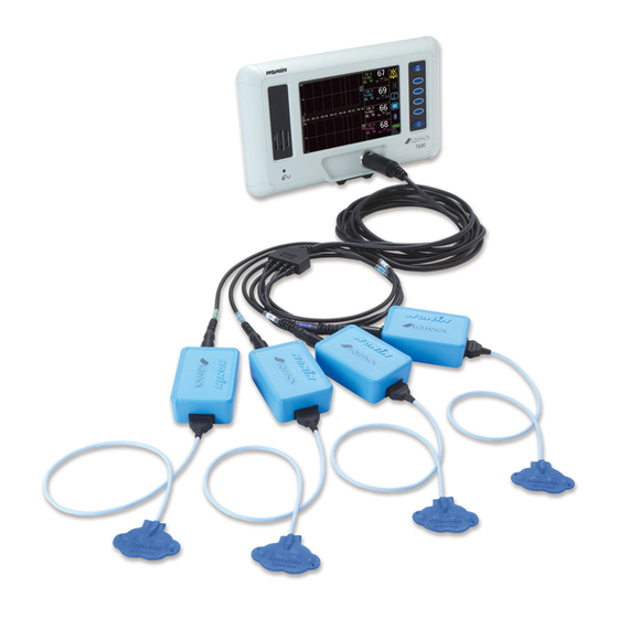
Introduction to the Model 7600 Pod > Intermediate Cable > Sensor Pod > Sensor Pod > Sensor (8204CA) (8004CA, 8003CA) (8004CB, 8004CB-NA) Pods (contain oximeter) Examples above illustrate sensor to pod connection Display Trunk Cable Figure 2: Setting Up the Monitor (Two-Channel Trunk Cable Shown) -
Page 18: Connect/Disconnect A Sensor To The Intermediate Cable
Introduction to the Model 7600 Connect/Disconnect a Sensor to the Intermediate Cable NOTE: The INT-100 is used to connect the 8204CA (patients ≥40 kg) sensor to the pod. 1. To connect: a. Slide the sensor lock on the INT-100 away from the port. -
Page 19: Monitoring A Patient
Each time the device is turned ON, the 7600 monitor clears the baseline values, resets the limits to the default values, and begins a new patient record in data memory. -
Page 20: Battery
Introduction to the Model 7600 Battery Battery capacity: 7.4 V Li-ion battery pack, 3.8 Ah when charged with the Model 7600 Operating life (fully charged battery): 3 hours minimum Storage life: 20-day minimum Recharge time to 90% capacity: 2.5 hours maximum CAUTIONS: •... -
Page 21: Displays, Indicators, And Controls
Displays, Indicators, and Controls Displays, Indicators, and Controls This chapter describes the displays, indicators, and controls for the Model 7600. Figure 5 shows operation when pods are only connected to channels 1 and/or 2. If pods are connected to channels 3 and/or 4, the system will automatically display all four channels (figure 6) (four-channel accessory kit required). -
Page 22: Displays
Displays %rSO The %rSO displays, located on the right side of the 7600 monitor front panel, show %rSO blood oxygen saturation from 0 to 100%. The device continually displays an rSO trendline for each monitored channel. The channel background display flashes: •... -
Page 23: Auc (Cumulative Saturation Below Low Alarm Limit)
Displays, Indicators, and Controls AUC (Cumulative Saturation Below Low Alarm Limit) For each channel, the rSO values below the low alarm limit are integrated together and displayed as the cumulative saturation below low alarm limit, also known as AUC (Area Under the Curve). -
Page 24: Indicators And Controls
AC Power Adapter LED This light-emitting diode (LED) indicator is lit when an external power supply is providing power to the Model 7600. It is YELLOW when the battery pack is charging and GREEN when the battery pack is fully charged. -
Page 25: Table 7. Front Panel Buttons
When on, pressing this button for at least 1 second shuts down the 7600, putting it into Standby mode. In Standby mode, all device functions are shut off, with the following exceptions: •... -
Page 26: Figure 7. Monitoring Screen Buttons
Displays, Indicators, and Controls Event Mark Limits Menu Settings Menu Bluetooth Figure 7: Monitoring Screen Buttons Table 8: Monitoring Screen Buttons Symbol Description Event Mark Pressing this button marks an event in memory and on the trendline. Events are denoted by increasing alphabetic letters. Limits Menu Pressing the Limits Menu button opens the Baseline screen. -
Page 27: Figure 8. Menu Buttons
Displays, Indicators, and Controls Plus Minus Next Save Figure 8: Menu Buttons Table 9: Menu Buttons Symbol Description Plus (+) and Minus (-) These buttons adjust values for the highlighted field. Next Press this button to move to the next option. Available settings appear in blue. -
Page 28: Using The Model 7600 Regional Oximeter
NOTES: • Before using the Model 7600, please review all contraindications, warnings, and cautions. • Before using the Model 7600 for the first time, the battery should be charged for 4 hours. Verifying System Operation CAUTION: Between patients, turn the Model 7600 off (Standby mode). Failure to do so could result in inaccurate baseline values for the new patient. -
Page 29: Connecting Devices With Bluetooth
WARNING: The user must verify the device Bluetooth pairing to ensure the correct patient is remotely monitored. NOTE: If the Bluetooth radio in the 7600 monitor needs to be disconnected from the host device, there are three ways to disconnect it: 1) use the host device, 2) disable the monitor’s Bluetooth radio (see “Disable BT”), or 3) cycle power on the monitor. -
Page 30: Event Mark
Event Mark button is pressed. The label (sample below) provides the following information: • Event date and time (if date and time are set correctly on the 7600). • Space to write a patient summary for the event. The event mark letter also displays here. -
Page 31: How To Use The Dymo Printer
Using the Model 7600 Regional Oximeter How to Use the Dymo Printer 1. Set the RS-232 port to “Printer.” a. Press Settings Menu b. Press Next to move through the settings and select “USER Menu.” c. Monitor displays “Press Special Keys.” Press Plus (+) and Minus (-) at the same time to enter the USER Menu. -
Page 32: Operating Menus And Defaults
Operating Menus and Defaults Operating Menus and Defaults When operating the Model 7600, the user can choose to have the low alarm limit values set automatically. When the Auto Low Alarm setting is ON (default), the device reads the baseline values and automatically calculates the low alarm limit values as a percentage below the baseline (factory default is baseline minus 25%). -
Page 33: Limits Menu
Operating Menus and Defaults Limits Menu The two screens of the Limits Menu, Baseline and Limits, can be accessed by pressing the Limits button. All adjustments are made using the blue soft buttons: Plus (+), Minus (-), Next , and Save •... -
Page 34: How To Set The Baseline - All Channels To Current %Rso 2 Value
NOTE: Baseline values are set when the Baseline screen closes. If Save is not pressed and the rSO values change during the 10-seconds before time out, the 7600 will save the rSO values that are on the display at time out. If an adjustment to a baseline value is needed, see “Baseline Adjustment”... -
Page 35: Figure 13. Limits Screen (Auto Low Alarm-On)
Operating Menus and Defaults Alarm Limit %rSO High Alarm Limit %rSO ↓ Baseline Baseline Adjustment Figure 13: Limits Screen (Auto Low Alarm–ON) When Auto Low Alarm is OFF, the Limits screen (figure 14) allows the user to adjust/review the following fields by channel: •... -
Page 36: How To Set Limits
Operating Menus and Defaults Table 10: Alarm Limit Setting Options Alarm Limit Factory Default Adjustment Options Increment High 20 – 95% (Auto Low Alarm–OFF) 15 – 90% Baseline - 25% (Auto Low Alarm–ON) (Baseline minus 25%) - 40% to - 5% (minus 40% to minus 5%) WARNING: Verify all alarm settings and limits during system startup to ensure that they are set as intended. -
Page 37: Baseline Adjustment
Operating Menus and Defaults If the baseline is modified, the Low Alarm Limit display automatically updates, and the AUC recalculates from the beginning of the current record. ↓ NOTE: The AUC will not calculate if the Alarm Limit %rSO Low % Baseline setting is OFF. -
Page 38: How To Change Display Timescale
Operating Menus and Defaults Figure 15: Main Menu How to Change Display Timescale Display Timescale is the range of data time displayed on the screen. This setting does not affect stored data. 1. Press Settings Menu 2. Press Plus (+) or Minus (-) to change the Timescale to the desired setting. Available settings are 7.5 minutes, 15 minutes, 30 minutes, 1 hour, 2 hours, 4 hours, 8 hours, 12 hours, and 24 hours. -
Page 39: How To Enable/Disable The Hbi Display
Operating Menus and Defaults How to Enable/Disable the HbI Display 1. Press Settings Menu 2. Press Next to move through the settings and select “HbI Display.” 3. Press Plus (+) or Minus (-) to turn the HbI display ON or OFF. 4. -
Page 40: How To Clear Memory
Operating Menus and Defaults How to Clear Memory 1. Press Settings Menu 2. Press Next to move through the settings and select “Clear Memory.” 3. Default setting is NO. Press Plus (+) or Minus (-) to select YES. 4. Press Save 5. -
Page 41: How To Enter The User Menu
WARNING: Verify all alarm settings and limits during system startup to ensure that they are set as intended. Factory Defaults In Factory Defaults, alarm limits are set as indicated in table 11. These are the Model 7600’s default operating settings. The Model 7600 is shipped with factory defaults active. -
Page 42: User-Defined Defaults
WARNING: Verify all alarm settings and limits during system startup to ensure that they are set as intended. WARNING: A hazard can exist if different defaults are used on multiple 7600 monitors in one care area. NOTE: All User-Defined Default settings are retained even when both external and battery power are lost. -
Page 43: Auto Low Alarm
Operating Menus and Defaults Auto Low Alarm When the Auto Low Alarm setting is ON (factory default setting), the Model 7600 automatically calculates the low alarm limit as a percentage below the baseline. For more information, see the “Alarm Limit %rSO Low”... -
Page 44: How To Set Real-Time Bluetooth And Rs-232 Data Formats
Operating Menus and Defaults How to Set Real-time Bluetooth and RS-232 Data Formats 1. Press Settings Menu 2. Press Next to move through the settings and select “USER Menu.” 3. Monitor displays “Press Special Keys.” Press Plus (+) and Minus (-) at the same time to enter the USER Menu. -
Page 45: Alarms
Alarms Alarms The Model 7600 has audio and visual alarm indicators to alert the operator in case immediate patient attention is required or an equipment alarm occurs. The intended operator’s position for correctly perceiving a visual alarm signal and its priority is 1 meter (3.3 feet). -
Page 46: Silencing Alarms
1. Turn the unit off and then back on again to remove the error code. 2. If the error persists, note the error code and contact Nonin Technical Service at (800) 356-8874 (USA and Canada), +1 (763) 553-9968, or +31 (0)13 - 79 99 040 (Europe). -
Page 47: Memory And Data Output Features
The Model 7600 provides real-time patient data output for rSO . The device may be connected to a PC via a Bluetooth connection or using the RS-232 serial data port on the back of the 7600 monitor (figure 17). Figure 17: RS-232 Serial Data Port NOTE: Use only a null modem serial cable to connect the Model 7600 to a PC. -
Page 48: Connecting The Device Into A Medical System
Data Formats”). On the USER Menu, the Bluetooth and RS-232 ports have separate selection options and may use different data output formats. When using eVISION software with the 7600, the port used to download data (either Bluetooth or RS-232) must be set to Nonin 1 before connecting to eVISION. -
Page 49: Nonin 1
=xxx,xxx,xxx,xxx|HbI=xx.x,xx.x,xx.x,xx.x| AUC=xxxx,xxxx,xxxx,xxxx|REF=xxx,xxx,xxx,xxx|HI_LIM=xxx,xxx,xxx,xxx| LOW_LIM=xxx,xxx,xxx,xxx|ALM=xxx,xxx,xxx,xxx|SIG_QUAL_ALM=x,x,x,x| POD_COMM_ALM=x,x,x,x|SNS_FLT=x,x,x,x\LCD_FLT=x\ LOW_BATT=x\CRIT_BATT=x\BATT_FLT=x\STK_KEY=x\SND_FLT=x\ SND_ERR=x\EXT_MEM_ERR=x\CKSUM=xxxx<CR><LF> NOTE: The 1234&$* order shall be preserved in all alarm conditions. Table 13: Nonin 1 Data Output Format Following Parameter Value Delimiter Ch1=XXX Channel 1 regional oximeter value. space Leading zeros blank; --- if no value available. - Page 50 Memory and Data Output Features Table 13: Nonin 1 Data Output Format (Continued) Following Parameter Value Delimiter HbI=xx.x,xx.x,xx.x,xx.x Hemoglobin index values for channels 1,2,3,4 in grams per deciliter. Leading zeros blank; --.- if no value available. AUC=xxxx,xxxx,xxxx,xxxx Area under curve for channels 1,2,3,4. Leading zeros blank.
- Page 51 Memory and Data Output Features Table 13: Nonin 1 Data Output Format (Continued) Following Parameter Value Delimiter EXT_MEM_ERR=x External memory error indicator. 0 = no external memory error active. 1 = external memory error active. CKSUM=xxxx CRC-16 CCITT (XMODEM) of all parameters <CR><LF>...
-
Page 52: Nonin 2
Memory and Data Output Features Nonin 2 Baud Rate 9,600 Delimiter Comma [0x2C] Line Terminator CR [0x0D] LF [0x0A] Column 1 Column 2 Column 3 Column 4 Current value Current value Average of Channel 1 and Channel 2 of Channel 1 of Channel 2 Missing data is output as -1. -
Page 53: Nonin 3
Memory and Data Output Features Nonin 3 Baud Rate 9,600 Delimiter One or more consecutive spaces [0x20] Line Terminator LF [0x0A] CR [0x0D] Channel Version Date Time Event Status Baseline AUC UAL LAL A Name 99.99.99/1/1 mm/dd/yy hh/mm/ss These columns repeat per channel... -
Page 54: Nonin 4
Memory and Data Output Features Nonin 4 Baud Rate 9,600 Delimiter One or more consecutive spaces [0x20] Line Terminator LF [0x0A] CR [0x0D] Sensor Sensor Sensor Sensor Date Time Event Status A B ID 1 ID 2 ID 3 ID 4... -
Page 55: Nonin 5
Memory and Data Output Features Nonin 5 This data format was designed to be extensible. Future enhancements to the Model 7600 may be included in the data output. As these enhancements become available, new column labels may be added at any position within the data format. -
Page 56: Memory Features
7600 monitor. Each data record in the Model 7600 system is identified by date and time. On a host computer, files are identified by this data, extracted, and stored as either raw data or as a .pdf. The files comply with standards defined in the STS National Adult Cardiac Surgery Database. -
Page 57: Care And Maintenance
Field repair of the Model 7600 is not possible. Do not attempt to open the Model 7600 case or repair the electronics. Opening the case may damage the Model 7600 and void the warranty. -
Page 58: Parts And Accessories
For more information about Nonin parts and accessories: • See the Part and Accessories List on the operator’s manual CD. • Contact your distributor or Nonin at (800) 356-8874 (USA and Canada), +1 (763) 533-9968, or +31 (0)13 - 79 99 040 (Europe). -
Page 59: Troubleshooting
The unit has no power. Plug in the AC adapter. activate. Model 7600 will not The battery pack is not Plug in the Model 7600 AC Adapter to operate on batteries. charged. charge the battery pack. The battery pack is Contact Nonin Technical Service for inoperable. - Page 60 If problem persists, contact Nonin Technical Service. If these solutions do not correct the problem, please contact Nonin Technical Service at (800) 356-8874 (USA and Canada), +1 (763) 553-9968, or +31 (0)13 - 79 99 040 (Europe).
-
Page 61: Service, Support, And Warranty
Please consult your local Nonin distributor for additional information. Nonin shall repair or replace any Model 7600, 7600PA, trunk cable, or INT-100 found to be defective in accordance with this warranty, free of charge, for which Nonin has been notified by the purchaser by serial number that there is a defect, provided said notification occurs within the applicable warranty period. - Page 62 This warranty excludes cost of delivery to and from Nonin. All repaired units shall be received by the purchaser at Nonin's place of business. Nonin reserves the right to charge a fee for a warranty repair request on any device that is found to be within specifications.
-
Page 63: Technical Information
Technical Information Technical Information NOTE: This product complies with ISO 10993, Biological Evaluation of Medical Devices Part 1: Evaluation and Testing. CAUTION: A functional tester cannot be used to assess the accuracy of the oximeter monitor or sensor. CAUTION: Portable and mobile RF communications equipment can affect medical electrical equipment. -
Page 64: Table 15. Electromagnetic Immunity
Technical Information Table 15: Electromagnetic Immunity Electromagnetic Immunity Test IEC 60601 Test Level Compliance Level Environment—Guidance This device is intended for use in the electromagnetic environment specified below. The user of this device should ensure that it is used in such an environment. Electrostatic Discharge ±6 kV contact ±6 kV contact... -
Page 65: Table 16. Guidance And Manufacturer's Declaration-Electromagnetic Immunity
Technical Information Table 16: Guidance and Manufacturer’s Declaration—Electromagnetic Immunity IEC 60601 Compliance Immunity Test Electromagnetic Environment—Guidance Test Level Level This device is intended for use in the electromagnetic environment specified below. The user of this device should ensure that it is used in such an environment. Portable and mobile RF communications equipment should be used no closer to any part of the device, including cables, than the recommended separation distance calculated from the equation applicable to the frequency of the transmitter. -
Page 66: Equipment Response Time
Technical Information Table 17: Recommended Separation Distances This table details the recommended separation distances between portable and mobile RF communications equipment and this device. This device is intended for use in an electromagnetic environment in which radiated RF disturbances are controlled. Users of this device can help prevent electromagnetic interference by maintaining a minimum distance between portable and mobile RF communication equipment (transmitters) and the device as recommended below, according to maximum output power of the communications equipment. -
Page 67: Testing Summary
Testing Summary Principles of Operation Model 7600 oximeter pod uses calculations based on the Beer-Lambert law or Beer’s law, to determine regional oxygenation. The Beer-Lambert law relates the absorption of light to the properties of the material through which the light is traveling. The law states that there is a logarithmic relationship between the concentration of compounds and the transmission of light through it. -
Page 68: Specifications
100–240 VAC 50–60 Hz Internal Power: Battery: 7.4 volt Li-ion battery pack, 3.8 Ah when charged with the Model 7600. Operating Life (fully charged battery): 3 hours minimum Storage Life: 20 days minimum Recharge Time to 90% Capacity: 2.5 hours maximum... - Page 69 Technical Information Dimensions: 7600: Approximately 305 mm (12.0 in.) W x 180 mm (7.2 in.) H x 130 mm (5.0 in.) D 7600PA: Approximately 85 mm (3.25 in.) W x 30 mm (1.25 in.) H x 60 mm (2.25 in.) D INT-100: Approximately 40.6 cm (16 in.)
-
Page 70: Transmitter
Technical Information Transmitter Bluetooth Compliance: Version 2.0 Operating Frequency: 2.4 to 2.4835 GHz Output Power: < 20 dBm Operating Range: 100-meter (328-feet) radius indoors (line of sight when connected to a class I device) Network Topology: Star Operation: Bluetooth Slave Antenna Type: Internal Modulation Type:... -
Page 71: External Monitor Installation Instructions
Baud Rate (7600 Communication to Interface Module): 19200 Word Length: 8 Bit Start Bit: 1 Stop Bit: 1 Parity: None NOTE: To support communication, the 7600 monitor must have display software revision 011 or higher (DPY = 011, as shown on the initial screen). -
Page 72: Connecting The 7600 To The Philips Monitor
7600 to a Philips monitor may be delayed by several seconds. 7600 Configuration The Model 7600 is a plug and play device. It does not require any configuration to be used with the Philips monitor. The 7600 detects the connection and begins communicating automatically. -
Page 73: Figure 18. 7600 Connection To Philips Monitor With Vuelink
Philips monitor (contact a Philips authorized technician if the VueLink Interface Module has not been configured). 7. Communication between the 7600 and Philips monitor should be established within approximately 45 seconds. Once established, PHILIPS displays on the right side of the 7600 LCD (figure 19). -
Page 74: Setting Up The Connection - Intellibridge
4. Connect the patch cable to the IntelliBridge EC5 ID module. 5. Connect the EC5 module to the RS-232 serial data port on the back of the 7600. Use the screws to secure the module to the serial data port. -
Page 75: Philips Monitor Display Configuration
Setup Philips Monitor with VueLink Interface Module to Display 7600 Numerics 1. Connect the 7600 to the Philips monitor (see the “Setting up the Connection” section). 2. Verify the 7600 and Philips monitors are on. 3. On the Philips monitor, enter Configuration Mode by selecting Main Setup key. -
Page 76: Setup Philips Monitor With Intellibridge Interface Module To Display 7600 Numerics
21. Turn the Philips monitor back on. Monitor is ready to use. Setup Philips Monitor with IntelliBridge Interface Module to Display 7600 Numerics 1. Connect the 7600 to the Philips monitor (see the “Setting up the Connection” section). 2. Verify the 7600 and Philips monitors are on. - Page 77 Philips monitor. White box displays on monitor. c. Select the white box to open the Change Numeric window. NOTE: If the Change Numeric window does not open, that location is not available for 7600 numerics. d. Scroll up or down to see the 8 numerics.
-
Page 78: Alerts
• The interface does not allow the Philips monitor to generate audible signals at the bedside for alarms and inops generated by the 7600. Patient Alarms The Open Interface Protocol defines two types of patient alarms: •... -
Page 79: Equipment Alarms
**rSO LOW WARN displays. Alarm indicator flashes yellow. NOTE: For more information on 7600 alarms, see the “Alarms” chapter. Equipment Alarms The Philips monitor displays equipment alarms as “inops” or “inoperatives.” Each inop carries information either on the validity of all related measurements (general inop) or on the validity of a specific numeric.
Need help?
Do you have a question about the 7600 and is the answer not in the manual?
Questions and answers