Table of Contents
Advertisement
Quick Links
Advertisement
Table of Contents

Related Manuals for Laguna Tools Platinum Series


Summary of Contents for Laguna Tools Platinum Series
- Page 1 Platinum Series Dovetail Manual LAGUNA TOOLS 2072 Alton Parkway Irvine, California 92606 Ph: 800.234.1976 Model Numbers: MDO0232-0050 www.lagunatools.com © 2018, Laguna Tools, Inc. LAGUNA® and the LAGUNA Logo® are the registered trademarks of Laguna Tools, Inc. All rights reserved.
- Page 2 PREFACE We appreciate your purchase of our machine. This machine is designed and manufactured for efficient, multi purpose operations. This manual concerns the operation, safety and maintenance of the machine. This manual should be kept readily available to the operator for reference. The operator should read this manual carefully before operation to ensure safe, smooth operation of the machine.
- Page 3 Machines sold through dealers must be registered with Laguna Tools within 30 days of purchase to be covered by this warranty. Laguna Tools guarantees all new machines and accessories sold to be free of manufacturers’...
- Page 4 1. SAFETY INSTRUCTION 1.1. SAFETY REGULATIONS 1.1.1. GENERAL SAFETY RULES Do not attempt to operate until you have read thoroughly WARNING and understand completely all instructions, rules, etc. contained in this manual. Failure to comply can result in accidents involving fire, electric shock, or serious personal injury.
- Page 5 1. SAFETY INSTRUCTION 9. USE THE RIGHT TOOLS. Do not force the machine or attachments to do a job for which they were not designed. 10. WEAR PROPER APPAREL. Avoid loose clothing, gloves, neckties, rings, bracelets, or jewelry, which could be caught in moving parts.
- Page 6 1.1.2. ADDITIONAL SAFETY RULES FOR MILLING MACHINE 1. Proper operation of this machine requires the specific knowledge of the following instructions and of the risks consequent to improper utilization. 2. Therefore only qualified and authorized personnel must operate the machine. The operator will be trained on the proper use of the equipment, its protection devices and accessory tools.
-
Page 7: Safety Instruction
1. SAFETY INSTRUCTION 9. Keep the machine power off when not in use. 10. The machine does not include its own illumination. User must provide appropriate lighting of working area. 11. The machine may not be operated in environments polluted by gas and flammable compounds. -
Page 8: Specifications
2. SPECIFICATIONS 2.1. SPECIFICATIONS MODEL On board machine installed power 3.7 kw Working pressure 1.7 bar Number of spindles Spindle revolutions 21.500 rpm Max working width 480 mm Center tot center of indents 25 mm Max height indents 18 mm Max thickness front 60 mm Max thickness sides... -
Page 9: Function Of The Machine
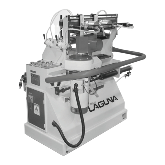
2. SPECIFICATIONS 2.2. FUNCTION OF THE MACHINE The milling machine is utilized to indent dovetails for drawers and various furniture elements. The machine is equipped with a mill spindle which allows cutting of indents of adjustable height. The machine can cut single male or female work pieces or both simultaneously. - Page 10 2. SPECIFICATIONS 2.3. LEGEND OF THE MACHINE 2.4. DIMENSIONAL LIMITS OF WORKPIECES Dimensions Minimum Maximum Length 200 mm 1500 mm Width 60 mm 480 mm Indent Height 6 mm 18 mm Front Thickness 60 mm Side Thickness 10 mm 30 mm...
-
Page 11: Installation
3. INSTALLATION 3.1. SAFETY RULES FOR MACHINE LIFTING 1. Pay special attention to the balance of the machine while lifting. 2. Use a forklift or a hydraulic hand pallet truck with sufficient loading capacity to lift the machine. 3. Have another person help guide the way when lifting the machine. 4. - Page 12 3. INSTALLATION 3.4. INSTALLATION AND LEVEL ADJUSTMENT Once the machine has been placed at a solid and level concrete floor. Leave proper space around the machine for handing the materials to be machined. Perform leveling adjustment on the machine to ensure milling efficiency. After the machine has been located at a proper work site, proper leveling needs to be made.
-
Page 13: Power Supply Requirement
3. INSTALLATION 3.5. POWER SUPPLY REQUIREMENT Insufficient voltage from factory power source may affect the power output of the motor. It is important to connect this machine to the correct voltage in the factory power source. Use only an independent power source. Table for power supplies requirement Voltage Current... -
Page 14: Compressed Air Connection
3. INSTALLATION 3.7 CHECK POWER WIRES CONNECTION 1. After the power wires have been connected it is necessary to check if the power wires are connected to the correct connection points. 2. Turn on the power switch (A) on the control cabinet. 3. - Page 15 3. INSTALLATION 3.9. CONNECT DUST COLLECTION SYSTEM 1. There is a dust hood provided on the mill cutter unit for sucking dust from the machine. 2. Fit the flexible hose to the dust hood (A) and connect it to the dust collector. 3.
- Page 16 4. OPERATION 4.1. CONTROLS 4.1.1. SWITCHES FUNCTION ON ELECTRICAL CONTROL PANEL 4 5 6 7 SWITCH NAME FUNCTION POWER SOURCE When turns the switch to the ON SWITCH position the machine is connected to the power and is ready to operate When the machine is not use.
-
Page 17: Operation
4.OPERATION SWITCH NAME FUNCTION EMERGENCY STOP In the event of any abnormality occurring during operation, the machine should be stopped immediately. MOTION MOTOR ress this switch for starting the START SWITCH motion motor. The switch light comes on. MOTION MOTOR ress this switch to stop the STOP SWITCH motion motor. - Page 18 4. OPERATION SWITCH NAME FUNCTION MILLING SPINDLE ress this switch to the milling STOP SWITCH spindle. MILLHEAD TRAVEL hen the operate mode MANUAL TART selection switch are set to right SWITCH position. The switch must be pressed for start automatic return travel.
- Page 19 4. OPERATION 4.2. MACHINE ADJUSTMENT 4.2.1. THE NOTICE BEFORE OPERATION The nozzles need to pour the oil regularly for maintaining th lubrication Before operation, the oil cups’ switches need to be pulled up Switch pulled up The cups need to be in eighty percent of oil When there is no using, the switches need to be pulled down...
- Page 20 4. OPERATION 4.2.2. Adjustment for the thickness of work piece djust the height of locking actuators assembly(A) by rotating adjustment nuts (B), which allowsraising or lowering such assembly (C). 4.2.2. Adjustment of positi on of work piece etermine the position of work piece for indent cutting, position horizontal and vertical fixtures (A , B) and fix them by tightening the screws (C).
- Page 21 4.2.3. Adjustment of indent height “H” Choose on spindle shaft (A) the desired height. The lowest value of 6mm. is obtained by positioning the mill cutter on the first notch to the left of the scale, identified with minus (-) sign, and lock the setscrew (B). Each notch of the scale will increase the indent height of 1mm.
- Page 22 4.2.5. Adjustment of female indent depth “S1” Position the support of mobile chaser to beginn ing of travel forward, loosen handwheel (A) operate the register (B) to desired depth and lock handwheel. 4.2.6. Adjustment of automa tic return tra vel of mill head: Return travel limit can be positioned at any point to speed up p rocess when working small parts.
- Page 23 4.2.7. Adjustment of return speed of mil head assembly: Adjust flow regulator (A) to reach the desired speed. 4.2.8. Adjustment of return speed of copying shaft Adjust flow regulator (A) to reach the desired speed. Warning The return speed of copying shaft into the chaser must be kept adequately slow. 4.2.9.
-
Page 24: Working Cycle
4.2.10. Adjustment of mill head assembly speed Change gear ratio of motor (A) shifting the belt(B ) on pulleys (C, D). 4.3. WORKING CYCLE Locking work piece takes place with a 4mm travel of the piston. Such small gay revents operator’s fingers to get caught between pusher and work piece inadvertentl WARNING A chine operator mu st pay maximum attention in the work piece locking area... -
Page 25: Maintenance
4.3.1. Simultaneous work of male-female elements . Work pieces to be cut with male indents between vertical bed (A) and pushers (B) striking them on fixed chaser (C). Lock pushers by means of manual valves (D). . Insert work pieces to be cut with female indentsbetween horizontal and pushers until they strikeon work pieces previously locked on the verticalbed. -
Page 26: Routine Maintenance
This machine is designed and manufactured for easy operation and maintenance. Design technical solutions, materials used, protective coatings, were planned to reduce maintenance requirements. Nevertheless we recommend performing a set of tasks with the aim to grant machine safety, reliability and efficiency in the long run. .1. -
Page 27: Electrical Wiring Diagram
6. ELECTRIC ELECTRICAL WIRING DIAGRAM... - Page 28 6. ELECTRIC...
- Page 38 Laguna Tools is not responsible for errors or omissions. Specifications subject to change. Machines may be shown with optional accessories. © 2018, Laguna Tools, Inc. LAGUNA® and the LAGUNA Logo® are the registered trademarks of Laguna Tools, Inc. All rights reserved.
Need help?
Do you have a question about the Platinum Series and is the answer not in the manual?
Questions and answers