
Related Manuals for Laguna Tools P12 5


Summary of Contents for Laguna Tools P12 5
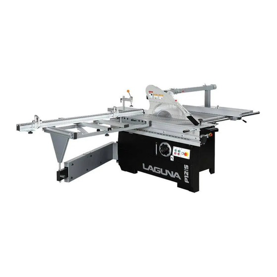
- Page 1 Owner’s Manual P12|5 Panelsaw MPSP12-5-0135 lagunatools.com | lagunacleanair.com | supermaxtools.com...
- Page 2 Aside from being free of defects upon receiving, consumable parts, like cutters and abrasives, are not covered by this warranty unless otherwise stated by Laguna Tools. These parts are designed to be used at the expense of the operator and are available for replacement or inventory purchase.
-
Page 3: Table Of Contents
Table of contents General information and safety rules……………………………………………………P2 Specification sheet……………………………………………………………………… P6 Main features…………………………………………………………………………… P7 Asseble and set up……………………………………………………………………… P7 1. Control Panel………………………………………………………………………… P7 2.Rip Fence ……………………………………………………………………………P7 3. Hold down…………………………………………………………………………… P8 4. Riving Knife & Saw blade…………………………………………………………… P8 5. Moving & fixed the base unit………………………………………………………… P8 6. - Page 4 Wiring diagram Parts list SSEM01-1.3 Machine body……………………………………………………………… SSEM01-3.1 Table ……………………………………………………………………….. ASSEM02-4 control panel …………………………………………………….... ASSEM03-1 Saw blade cover device…………………………………………………… ASSEM03-3 Saw blade movement device ……………………………………………… ASSEM03-4.1 Saw blade structure ………………………………………………….. ASSEM04-3 angel device ……………………………………………………………….. ...
-
Page 5: General Information And Safety Rules
1. GENERAL INFORMATION & SAFETY RULES Laguna Tools, Inc. specializes in supplying a full series of panel saws: from 1600, 2300, 2500, and 3200 to 3800mm. The design of this machine is unique, and includes an enlarged outrigger and carriage, and a direct dust collection outlet. We sincerely hope that you enjoy operating this machine. - Page 6 2) Ground all machines. It is important to make sure that the "PE" terminal is connected before operating the machine. 3) Keep guards in place and the work area clean. Keep guards in place and in working order. Keep the work area clean, as cluttered working enviromnets make accidents more likely.
- Page 7 If auxiliary equipment is removed, the original guards or safety devices must be replaced. Laguna Tools is responsible for a connection of the machine to auxiliary equipment only if the auxiliary equipment has been designed or specifically approved by Laguna Tools for used with this machine.
- Page 8 29) Do not load more than one workpiece at a time onto the machine. 30) When wood panels are cut, harmful dust is produced. The machine must be equipped with a proper dust-collecting system. 31) Use only properly sharpened and serviced saw blades. Never exceed the maximum RPM marked on the saw blade.
-
Page 9: Specification Sheet
Specification Sheet Model P30 (two motors) Cast iron fixed table 548x896mm dimension Sliding table dimension 1,600x378mm 2,200x395mm Main saw blade 305mm (Max. 355mm) Main saw bore 30mm Max. cutting height with blade at 90° 80mm Max. cutting height with blade at 45° 55mm Main motor power(3ph) 5HP(3Kw) -
Page 10: Main Features
Main Feature 1. Flip Stopper-Large stopper for accurate measurements 2. Crosscut Fence-90° and 45° quick position design for a precise crosscutting operation 3. Hold Down : Strong design with fine adjustment and floating rubber pad. 4. Saw Blade Guard : Fully adjustable blade maintains maximum protection around the saw blades. 5. -
Page 11: Hold Down
(3) Hold Down A. Fine adjustment handle B. Floating rubber to fix the wood firmly (4) Riving knife and saw blade 1. Riving knife:Maintains kerfs opening during cutting operations. The Purposes crucial to preventing kick back caused by the kerfs closing behind the blade. 2. -
Page 12: Scale Adjustment
4. Attach the small extension table with cap screws, washer and flat washers (Fig. 7) Upper lock 5. Check the surfaces 0 degree the table with a straightedge (Fig. 8) 6. Assemble the support bracket into the extension table (we have rest holes for fixing), then adjust the leveling screw of foot studs in order to make left ext. -
Page 13: Rip Fence
How to adjust the rip fence 1. Thread 4pcs M12-1.75 x 115 studs into round rail. 2. Thread an M12-1.75 hex nut onto each stud and tighten the nuts against the round rail 3. Thread an M12-1.75 hex nut and a flat washer half way onto each studs Fig. -
Page 14: Cross Table
(9) Cross table Crosscut content: Crosscut table x 1 Crosscut table brace x 1 T-nut M8-1.25 x 2 T-nut M12-1.75 x 1 Flat washer 12mm x 1 Adjustment handle M12-1.75 x 55 x 1 Knob M8-1.25 x 25 x 2 Fig. -
Page 15: Sliding Table
4. Insert the center stud and the T-bolt in the places center indicated (Fig. 23) stud 5. Secure the crosscut fence with the M8-1.25 knob with placement and 8mm flat washer threaded onto the T-bolt. 6. Unlock the crosscut fence extension and slide the flip stops into the fence (Fig. -
Page 16: Main Blade
(12) Main Blade Main blade content Blade 12" (as option) x 1 Flat belt 15 x 1,045 mm x 1 Riving knife x 1 This saw is designed with 12" main saw blade, before you change blade sizes, the riving knife must be adjusted to match the size of blade you install. -
Page 17: Scoring Blade
(13) Scoring Blade Aligning Scoring Blade Set Adjustng scoring The scoring blade must be aligned with the main blade to Adjusting ensure satisfactory cutting results. scoring rise/fall 1. Move the blade tilt to 0° (blade 90° to table) and raise the main blade all the way up. -
Page 18: Power Cord
Vertical 1. Secure a 4" dust hose to the dust port located under the saw table. (Fig. 38) 2. Run the 4" hose to your dust collection system. Slide the blade guard/dust hood over the riving knife and attach it with a M8-1.25 x 40 button head cap screw and a flat washer (Fig. -
Page 19: Change Main Blade
(1) Changing Main Blade The main blade size for this machine 12" , it is as option. Any time you change the blade size, adjust the riving knife to 3mm away from the blade you install. 1. Disconnect the power source. 2. -
Page 20: Change Scoring Blade
(3) Changing Scoring Blade 1. Discount the saw from the power source. 2. Move the blade tilt to 0° (blade 90° to table), and raise the scoring blade all the way up. 3. Move the sliding table all the way forward to expose the internal blade guard that covers the blade and riving knife. - Page 21 Trading Table Saw Cutting 1. Slide the crosscut table out of the way. 2. Lock the sliding table into a stationary position. (Fig. 49) table Fig. 49 3. Place the fence in the vertical position (Fig. 50) for larger workpiece, or in the horizontal position (Fig. 51) for angled cuts and for small workpiece.
-
Page 22: Crosscutting
(5) Crosscutting This saw can crosscut full size panels with the fence in forward mounted the forward or rear position, although it is easier to load full crosscut fence size panels with the crosscut fence mounted in the forward position. (Fig. 54) Fig. -
Page 23: Miter Cutting
Crosscutting using rip fence as a cut-off gauge 1. Install the crosscut fence in the rear mounting points (Fig. 58) and lock it in place. 2. Position the rip fence for the desired width. 3. Load the workpiece onto the table saw. 4. -
Page 24: Replace Belts
(8) Replace Belts To change V-belt for the main motor 1. Disconnect the saw from the power source. 2. Move the blade tilt to 0° (blade 90° to table ) and raise the main blade and scoring blade set up. 3. -
Page 25: Sliding Table Parallel Adjustment
(10) Sliding Table Parallel Adjustment The table is calibrated at the factory and please adjust if it changes during the transportation. Cover To adjust the sliding table parallel with the main blade: 1. Disconnect the saw from the power source. 2. -
Page 26: Troubleshooting
Troubleshooting WARNING Disconnect power to the machine when performing any 90° stop troubleshooting. Failure to do this may result in serious personal injury or death. Saw will not start 1. Check the switch is being depressed fully. 2. Check the electrical power cord is plugged into the power outlet. - Page 28 MPSP12-5-0135 ASSEM1.1.6...
- Page 29 MPSP12-5-0135 ASSEM1.1.6 PARTS NAME SIZE ITEM PART NO Q`TY NOTE Spring Pin PS062500 ψ6x25 Hex Head Bolt M10x40 SH100800 Hex Nut NH101700 Machine frame 206605 Washer M4xψ8 WF040808 Hex Nut NF040700 Hex Nut NH081300 Setscrew M8x25 SS080500 Cap Screw M5x5 SR050100 WS050000 Lock Washer...
- Page 30 MPSP12-5-0135 ASSEM1.1.6 PARTS NAME SIZE ITEM PART NO Q`TY NOTE Plate 206342 Plate 206345-32 Pan Head Screw(+)/W M6x10 SF060200 Base 207540 Washer M10xψ20 WF102030 Lock Washer WS100000 Cap Screw M10x35 SR100700 Steel Wire ASM AB207399 101 WF051210 Washer M5x12 Pan Head Screw M5x10 102 SP050200 Pointer...
- Page 31 MPSP12-5-0135 ASSEM1.1.6 PARTS NAME SIZE ITEM PART NO Q`TY NOTE Strain Relief MGB40-25B 207318 Hole Plugs HP-22 201458 Lock Washer WS120000 Plate 207080 Lock Washer WS060000 Cap Screw M6x12 SR069300 Cord Connetor 224-201 136019 Tap Screw ST049300 170736 Hanger Ring 203410...
- Page 32 ASSEM1.3.2 MPSP12-5-0135...
- Page 33 ASSEM1.3.2 MPSP12-5-0135 PARTS NAME SIZE Q`TY ITEM PART NO NOTE SS100400 Set Screw M10*20 Hex Nut NH101700 Left Ext. Plate 207077 Left Ext. Plate 207151 optional Cap Screw M10*25 SR100500 Table 206332 Ext. Plate 207078 Washer M10*ψ20 WF102030 Lock Washer WS100000 Button Head Screw M6*12...
- Page 34 MPSP12-5-0135 ASSEM2.4 PARTS NAME SIZE Q`TY ITEM PART NO NOTE Panel 206407 Button Head Screw SJ050200 M5x10 Emergency Stop Button 994808 Pilot Lamp 996002 YK.24V φ22 (W) Switch Button-ON 994855 R2 PNF-1A-G Dust Cove 994855A R2 PRCF 994856 Switch Button-OFF R2 PNF-1B-R...
- Page 35 MPSP12-5-0135 ASSEM3.1...
- Page 36 MPSP12-5-0135 ASSEM3.1 PARTS NAME SIZE Q`TY ITEM PART NO NOTE Cap Screw M6x12 SR069300 Lock Washer WS060000 Cap Screw M5x16 SR059400 Fix Plate 206337 Washer M5x10 WF051010 Lock Nut NL050800 Cap Screw M5x12 SR059300 Lock Washer WS050000 Hex Head Bolt(+)/W M8x12 SF089300 206301...
- Page 37 MPSP12-5-0135 ASSEM3.3 PARTS NAME SIZE Q`TY ITEM PART NO NOTE Belt (50hz) 3VX-265 208044 optional Belt (60hz) 3VX-250 206399 optional SS080200 Setscrew M8×10 Belt Pulley (CE) 50Hz 208043 optional Belt Pulley (CSA) 60Hz 208042 optional Shaft 201333 Main Motor Plate 206396 Washer M13×ψ22...
- Page 38 MPSP12-5-0135 ASSEM3.4.1 PARTS NAME SIZE Q`TY ITEM PART NO NOTE 206304 Gip Plate Button Head Screw M10×25 SJ100500 Spring Washer WS100000 5x5x20 KD050520...
- Page 39 MPSP12-5-0135 ASSEM3.4.1 PARTS NAME SIZE Q`TY ITEM PART NO NOTE M16x2.0 201822 Arbor Flange 206350 optional ψ25.4 Arbor Flange 206380 ψ30 Lock Washer WS080000 Washer M8×ψ30 WF083030 Bushing 200964 Shaft 201205 Button Head Screw M8×20 SJ080400 201346 Bushing Washer M8×ψ30 WF083030 Lock Washer WS080000...
- Page 40 MPSP12-5-0135 ASSEM4.3 PARTS NAME SIZE Q`TY ITEM PART NO NOTE 100203 Lock Knob Washer 204263 ψ10×ψ20 Washer 8" WF102730 hand wheel 206434A Washer 201567 Shaft 6006ZZ 206444 Bearing BB600602A Locate Plate 206409 Lock Washer M8×ψ18 WF081818 Lock Washer WS080000 Cap Screw M8x35 SR080700 Lock Washer...
- Page 41 MPSP12-5-0135 ASSEM4.3 PARTS NAME SIZE Q`TY ITEM PART NO NOTE Set Screw M6x6 SS069100 Set Nut 206379 7x7x20 KS070720 Cap Screw M10x20 SR100400 Lock Washer WS100000 Washer M10xψ40 WF104030 Shaft 206410 Set Screw M6x10 SS060200 Sprocket 207115 207461 Free Joint ψ14 Set Screw M6x6...
- Page 42 MPSP12-5-0135 ASSEM5.1...
- Page 43 MPSP12-5-0135 ASSEM5.1 PARTS NAME SIZE Q`TY ITEM PART NO NOTE Lock Knob 100203 Washer 204263 ψ10×ψ20 Washer M10×ψ30 WF103030 Hand Wheel 204289B optional Hand Wheel 204176A optional Bushing 200855 Sleeve 206385 Screw 206327 Setscrew M6×6 SS069100 206379 Set Nut Cap Screw M6×30 SR060600 Lock Washer...
- Page 44 MPSP12-5-0135 ASSEM6.2...
- Page 45 MPSP12-5-0135 ASSEM6.2 PARTS NAME SIZE Q`TY ITEM PART NO NOTE Pulley ASM AB206315-1 Hex Head Bolt M12×20 101 SH120440 Flange 102 206320 Shaft 103 206321 Ball Bearing 6202LLB 104 BB620204 Int. Retaining Ring 105 RS150000 Wave Washer 106 WW263403 ψ26xψ34 t=0.3 ( 6202 ) Int.
- Page 46 MPSP12-5-0135 ASSEM6.4 PARTS NAME SIZE Q`TY ITEM PART NO NOTE Cap Screw M12x100 SR122000 Lock Washer WS120000 Pully (50hz) 206314 optional Pully (60hz) 206336 optional Belt (60hz) 140J7 LJ014070 optional Belt (50hz) 150J7 LJ015070 optional 206313 Shaft Button Head Screw M8x20 SJ080400 Lock Washer...
- Page 47 MPSP12-5-0135 ASSEM7.1 ITEM PART NO PARTS NAME SIZE Q`TY NOTE Magnet 200934-2 Screw Threads For sliding table E 203416 Optional Screw Threads For sliding table D 205505A Optional...
- Page 48 MPSP12-5-0135 ASSEM7.1 PARTS NAME SIZE Q`TY ITEM PART NO NOTE Hex Nut M20x2.5p NH203000 Plug 40x120 203470 Set Screw M8x35 SS080700 Magnetic Bracket 201146-1 Sliding Tube 2200MM 207856 Optional Sliding Tube 3200MM 205208 Optional Sliding Tube 3800MM 205395 Optional Hex Head Screw M8x20 SH080400 NH081300...
- Page 49 MPSP12-5-0135 ASSEM8.1 ITEM PART NO PARTS NAME SIZE Q`TY NOTE T-Nut M8x1.25p 201103 Plug HP-16 203230 Handle 203128...
- Page 50 MPSP12-5-0135 ASSEM8.1 PARTS NAME SIZE Q`TY ITEM PART NO NOTE T-Block 201456 Adjust Handle M12x1.75px57L 200815 Knob Screw M8x50 200954 Knob Screw M8x50 200954 Support Frame ASM AB207996R Bearing 6201ZZ 101 BB620102A Bearing 102 017058 Roller 103 203302 104 200910 Plug 80x40 Support Frame...
- Page 51 MPSP12-5-0135 ASSEM9.3...
- Page 52 MPSP12-5-0135 ASSEM9.3 PARTS NAME SIZE Q`TY ITEM PART NO Flip Stop Assembly AB207207 Shaft 102 207203 Flip Stop 103 207207 Washer 104 207208 Knob M8x1.25px42L 105 207263 Washer M8x20x1 106 200472 Washer M8x18 107 WF081818 108 207235 109 207200 110 207201 Stop Bracket Pipe 111 207223...
- Page 53 MPSP12-5-0135 ASSEM9.3 PARTS NAME SIZE Q`TY ITEM PART NO Setscrew M8x12 SS089300 Rotate Shaft 206633 Fixed Block 207737 Washer M8x30 WF083030 Handle 203128...
- Page 54 MPSP12-5-0135 ASSEM10.1...
- Page 55 MPSP12-5-0135 ASSEM10.1 PARTS NAME SIZE Q`TY ITEM PART NO NOTE AB206422 Rip Fence Housing Assembly Counter Sunk Screw M6x16 101 SI069400 Fixed Plate 102 206433 Shafts 103 203193 Lock Nut 104 NL081000 Plate 105 200875 Hex Head Bolt M6x16 106 SH069400 Eccentric Ring 107 203179 Seat...
- Page 56 MPSP12-5-0135 2375160M PARTS NAME SIZE Q`TY ITEM PART NO NOTE Table 375x1600mm 2375160M Hander 2375320M-1 Hex Head Bolt M6x10 SJ060200 Fixed Block 206581 Cap Screw M8x25 SR080500...
- Page 57 MPSP12-5-0135 ASSEM12.9...
- Page 58 MPSP12-5-0135 ASSEM12.9 PARTS NAME SIZE ITEM PART NO Q`TY NOTE Lock Nut NL101700 Gas Expansion Cylinder 205004 Washer M10xψ20 WF102020 Cap Screw M6x20 SR060400 Lock Washer WS060000 Fixed Plate 207987 207970 Hose Clamp 3-1/4" 204158 HS330004 Hose ψ3"x42cm Washer 204263 ψ10×ψ20 Link 207981...
- Page 59 MPSP12-5-0135 ASSEM12.9 PARTS NAME SIZE ITEM PART NO Q`TY NOTE Hex Nut NH121900 Hex Head Bolt M12X70 SH121400 201039 Elbow Type Clamp 205358 Washer M8x18 WF081818 Lock Washer WS080000 Hex Nut NH081300 Cap Screw M8x30 SR080600 WF081818 Washer M8x18 Lock Washer WS080000 Cap Screw M8x25...
- Page 60 MPSP12-5-0135 ASSEM12.9 PARTS NAME SIZE ITEM PART NO Q`TY NOTE Shaft 208 207883 Protection Hood ASM AB205356 optional Guard 301 207867 Pan Head Screw M4x10 302 SP040200 Protection Hood 303 205356 Roller ASM 304 AB207868 Pan Head Screw M4x10 305 SP040200 Counter Sunk Screw M6x10 306 SI060200...
- Page 61 MPSP12-5-0135 ASSEM14.1 PARTS MA,E SIZE Q`TY ITEM PART NO NOTE Down Press ASM AB207065-1 101 207143 Adjust Handle Ball Knob M8×P1.25 102 100271 Handle Bar 103 207070 104 207067 Ext. Retaining Ring 105 RS140000 Spring 106 207069 107 207145 Down Press 108 207065 Shaft 109 207068...
- Page 62 MPSP12-5-0135 ASSEM14.2 PARTS NAME SIZE Q`TY ITEM PART NO NOTE Handle 200939 WF123030 Washer M12x30 Plastic Washer 992496 φ13xφ25 T-Nut M12x1.75p 201849...
- Page 63 MPSP12-5-0135 ASSEM14.3 PARTS NAME SIZE Q`TY ITEM PART NO NOTE Edge Shoe Plate Assembly AB201830 Edge Shoe Plate 101 201830 Spint Pin 102 PS051800 φ5xφ18 Washer M10x25 103 WF102025 104 203718 Knob T-Nut M10x1.5p 105 201829...
- Page 64 MPSP12-5-0135 ASSEM14.4.4...
- Page 65 MPSP12-5-0135 ASSEM14.4.4 PARTS NAME SIZE Q`TY ITEM PART NO NOTE Flip Stop Assembly No.101~111 AB200823 Flip Stop 101 200823 Rotation Shaft 102 200824 Knob M8x1.25px40L 103 200827 Stop Bracket 104 200826 T-Nut M8x1.25p 105 201103 Lock Nut 106 NL101700 Copper Washer 107 992610 ψ11*ψ18*0.5t 110 201170...
- Page 66 MPSP12-5-0135 ASSEM14.4.4 PARTS NAME SIZE Q`TY ITEM PART NO NOTE Ring 207668 Shaft 205253 Adjust Handle 207143 Ball Knob M8×P1.25 100271 Handle Bar 207070 207067 Ext. Retaining Ring RS140000 Spring 207069 207145 Down Press 207065 Shaft 207068 Hex Nut 5/16 NH602300 Large Washer 200807...
- Page 67 Laguna Tools is not responsible for errors or omissions. Specifications subject to change. Machines may be shown with optional accessories. © 2018, Laguna Tools, Inc. LAGUNA® and the LAGUNA Logo® are the registered trademarks of Laguna Tools, Inc. All rights reserved.
Need help?
Do you have a question about the P12 5 and is the answer not in the manual?
Questions and answers