Advertisement
Quick Links
Advertisement

Related Manuals for Laguna Tools MJOPL104200


Summary of Contents for Laguna Tools MJOPL104200
- Page 1 Jointer/ Planer Combination Machine Manual LAGUNA TOOLS 2072 Alton Parkway Irvine, California 92606 Ph: 800.234.1976 Model Number: MJOPL104200 www.lagunatools.com © 2017, Laguna Tools, Inc. LAGUNA® and the LAGUNA Logo® are the registered trademarks of Laguna Tools, Inc. All rights reserved.
-
Page 3: Table Of Contents
Table of contents Page number Safety Rules Warranty Noise emission Specification sheet Receiving your machine Introduction to your machine Parts of the machine Where to locate your machine Unpacking your machine Assembly and set up Adjusting the machine Using the machine Maintenance and troubleshooting Electrical drawing Exploded view drawings... -
Page 4: Safety Rules
Safety Rules As with all machinery there are certain hazards involved with the operation and use. Using it with caution will considerably lessen the possibility of personal injury. However, if normal safety precautions are overlooked or ignored, personal injury to the operator may result. If you have any questions relative to the installation and operation, do not use the equipment until you have contacted your supplying distributor. - Page 5 Machines sold through dealers must be registered with Laguna Tools within 30 days of purchase to be covered by this warranty. Laguna Tools guarantees all new machines and accessories sold to be free of manufacturers’...
-
Page 6: Noise Emission
Noise emission Notes concerning noise emission Given that there exists a relationship between noise level and exposure times, it is not precise enough to determine the need for supplementary precautions. The factors affecting the true level of exposure to operators are clearly the amount of time exposed, the characteristics of working environment other sources of dust and noise etc. -
Page 7: Receiving Your Machine
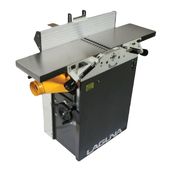
All damage must be noted on the delivery documents and signed by you and the delivery driver. You must then contact the seller [Laguna Tools] within 24 hours. Introduction to Jointer / planers The Jointer / planers are designed to give you years of safe service. - Page 8 through the end of the in feed table. Never stand or allow others to stand in this area during operation. If kick back occurs, severer injury may occur. 2. Cutter head alignment. To reduce the possibility of kickback. Keep the top edge of the out feed table aligned with the cutter head knife or insert at top dead centre (TDC).
- Page 9 injury and or fire. If you have any question about a piece of lumber do not use What you will receive with the jointer / planer. Parts Machine with box removed Fence...
- Page 10 Parts of the Jointer / planer The jointer / planer doe’s not have many parts. The major parts are discussed in this manual. If you are not familiar with the jointer / planer, take the time to read this section and become familiar with the machine. Cover removed...
- Page 11 1. Out feed Table. 2. In feed Table. 3. Fence. 4. Cutter head Guard. 5. Dust port. 6. Planer Table. 7. Depth Scale. 8. Planer Table Height Hand wheel. 9. Body.10. table adjusting handles. 18 Serial plate 11. Lock. 12. Start & stop switches. 13.
- Page 12 Note:- Never exceed the maximum depth of cut specified for your machine. It is far safer to take many small cuts rather than one large cut. Fence. The fence is used to keep the job square to the cutter head and is also used to produce angle cuts on the edges of panels.
-
Page 13: Where To Locate Your Machine
In feed handle is used to adjust the depth of cut Out feed handle is used to adjust the table level with the top of the cutter head when on top dead centre. Lock handle. The lock handle is used to lock planer table in position once the required setting has been set. -
Page 14: Unpacking Your Machine
will use your machine. There are no hard and fast rules for its location but below are a few guidelines. 1. There should be an area at the front and back of the machine suitable for the length of wood that you will be machining. 2. - Page 15 cause injury or damage. Remove them in order from the top and set aside. 4. Remove the base mounting bolts that secure the machine to the pallet. To access the mounting bolts you must remove the front cover. Pallet bolt Lifting bolt holes 5.
-
Page 16: Assembly And Set Up
and then move the machine to the vertical position so that it is completely resting on the floor Assembly & set up Levelling bolts 1. Raise the machine off the ground on to wooden blocks. 2. Fit a levelling bolt to the 4 corners of the machine. - Page 17 Fence clamp screw Fence clamp knob/ Fence fitted 90 degrees Fit the fence as shown. The fence can Angle clamp knob be adjusted from vertical to 45 degrees by loosening the angle clamp knob moving to the required angle and re clamping the knob.
- Page 18 Guard clamp handle Guard protector Fence clamp screw Guard angle adjusting screw Guard arm angle adjusting screw 1. Fit the guard arm to the machine in the position shown. 2. Holding the guard protector in position slide the guard into the arm and clamp in position with the clamp screw.
- Page 19 Note:- A qualified electrician must carry out the installation. Ensure that the main supply corresponds with that of the machine [Single phase 220 V]. It is recommended that you use a 30-amp mains breaker & a 30amp NEMA 6-30p plug. If you need a longer cable than that supplied on the machine, you can connect a new cable into the internal power termination.
- Page 20 Note:- the out feed table has a lock bar attached and has to be lifted first. Note:- The out feed table contacts a safety micro switch and the dust collection hood when in the plainer position also contacts the switch. This is a safety feature ensuring that the power is disconnected from the motor with the tables in the vertical position and the dust collection hood in the jointer position Note:- The planer table has to be lowered to the bottom of its travel before...
- Page 21 retaining clip is released and the plainer table is lowered to the bottom of its travel. Connecting the dust collection Connect a 4” flexible hose between the dust collection hood and your dust collector. Once fitted pull on the hose to ensure that the connection is tight.
- Page 22 Note:- Until you get experience with the machine, it is suggested that after setting the plainer thickness you machine a scrap piece of wood and check that the thickness is correct before you machine your production. Adjusting the jointer tables. Table lock handle Table height adjusting handle 1.
- Page 23 Receiving your mortiser Control handle Control handle Knob Clamp knob Chuck Clamp shaft Clamp Allen key Fitting the chuck...
- Page 24 Chuck Chuck fitted Mortiser mounting bolts Remove the chuck guard and fit the chunk. Note :- The thread is left hand. Refit the chuck guard. Remove the top mortiser mounting bolt. Then loosen the two lower mortiser mounting bolts. Slide the mortiser on to the lower bolts and fit the upper bolt. Tighten all the bolts.
- Page 25 Fit the handle to the vertical movement shaft. The mortiser comes factory set parallel to the spindle of the chuck. If adjustment is required, jacking screws are provided. To adjust the mortiser parallel to the spindle:- 1. Fit a long parallel bar into the chuck. 2.
- Page 26 Assemble and fit the work clamp. Clamp the vertical shaft to the work table with the nut and washer provided. Note: - The clamp can be fitted to either side of the table to suite the job that you are doing. Stop bars Stop Stops are provided to limit the sideways movement of the table to suit the job at...
- Page 27 Running and adjusting the machine. Cleaning the machine. The machine is shipped with the none painted surfaces protected from rust by a film of grease. The grease must be removed with WD40 or similar as it attracts saw dust and dirt.
- Page 28 Note:- The emergency stop button when pressed in with remain in the off position until re set. To re set the emergency stop button twist. Check that the emergency stop button is in the out position prior to conducting the below tests. 1.
- Page 29 Setting the out feed table to the cutter head. The out feed table must be level with the teeth / blade of the cutter head when the teeth / blade is at top dead centre [T.D.C.] 1. Rotate the cutter head so that the blade / teeth are at the T.D.C. position. 2.
- Page 30 Anti kick back teeth The anti kick back teeth must be free to Anti kick back teeth move or they will not for fill there function. With the power disconnected, check that all the teeth move freely. If they do not lubricate with Teflon based lubricant.
- Page 31 2. There is less chance of tare out. The disadvantage is that they are initially more expensive and that the surface finish is slightly wavy. This is caused because the teeth have a very slight radius. This waviness is easily removed by a light sanding. Fitting blades to parallel blade cutter head.
- Page 32 Maintenance As with any machine, to ensure optimal performance you must conduct regular maintenance. Daily checks. 1. Clean the machine and lubricate unpainted surfaces with a Teflon lubricant. Wipe off any excess and buff with a dry polishing cloth. This will reduce the likely hood of rust forming and reduce the friction on the tables as the wood is machined.
- Page 33 5. Re tension the belts. There should be a 3/16” deflection when the belt is pressed with moderate finger pressure. Tighten the motor clamping bolts. 6. The drive belts should be checked after running the machine for approximately 10 hours. The belts bed into the pulleys and will slacken off slightly.
- Page 34 Troubleshooting and fault finding. Problem Cause Corrective action Motor will not start 1. Emergency button 1. Rotate until the or fuses or circuit depressed. switch returns to off breakers blow. position 2. Short circuit 2. Repair or replace short circuit item. 3.
- Page 35 Loud noise coming 1. Motor pulley set 1. Replace or tighten if from machine. screws or keys are necessary. missing or loose 2. Drive belts are 2. Replace drive belts damaged. Tables are hard to 1. Table spindles are 1. Clean and lubricate adjust.
- Page 36 blades or teeth. Lines or ridges that run 1. Nicked or chipped 1. Replace blades or along the board blades or teeth. rotate or replace teeth. Chatter marks across 1. Blades not adjusted 1. Adjust the blades so the face of the board. at even heights.
- Page 40 Mortiser exploded drawing.
- Page 41 SPARE PARTS Part Name Part Name LIST No Socket hex cap Right and left screw support plate M6X16(SK) Motor plate Dust chute Defend plate Outlet Locking plate Side plate of dust chute Nylon bush Turning plate Support plate screw M5x6 Thicknessing Support axis table assembly...
- Page 42 assembly Adjusting bolt wheel M12X55 assembly Cutter block Bush assembly Ball bearing Bush bush Cutter block Sprocket Ⅳ pulley Protective Driving roller plate Special cutter Pressing roller block(SK) Blade locking Bush block Special Double head screw blade(SK) Part Name Part Name Spring Pin 3.2X30 Connecting...
- Page 43 plate(SK) Right sliding Locating bolt plate (SK) M6X16 Supporting Nut M16 bracket (SK) Protective “C” ring 15 cover Switch fixing Pin 6X16 plate Short locating Socket screw M6x16 Long locating Bolt M4x6 Square head Motor pulley screw M6X10 Locking Self – centre handle bearing 2206 Support plate...
- Page 44 switch Lubricating Hex cap screw injection hole M8x25 Seal Socket cap screw M6x40 Ball bearing Screw M5x50 51102 Washer 10 Elastic pin 4X14 Hex cap screw Socket cap screw M6x65 M6x16 Self-locking “C” ring 6 nut M10 Elastic Cap nut M6 4X25 Socket cap screw Elastic...
- Page 46 Laguna Tools is not responsible for errors or omissions. Specifications subject to change. Machines may be shown with optional accessories. © 2017, Laguna Tools, Inc. LAGUNA® and the LAGUNA Logo® are the registered trademarks of Laguna Tools, Inc. All rights reserved.
Need help?
Do you have a question about the MJOPL104200 and is the answer not in the manual?
Questions and answers