
Related Manuals for Laguna Tools P12 10


Summary of Contents for Laguna Tools P12 10
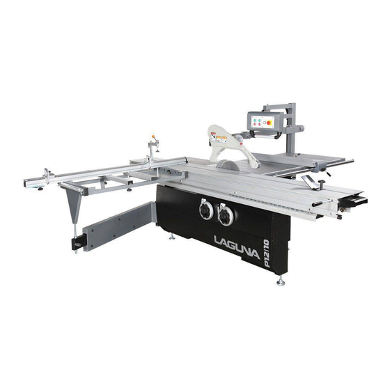
- Page 1 P12 10 Owner’s Manual P12|10 Panelsaw MPSP12-10-0135 lagunatools.com | lagunacleanair.com | supermaxtools.com...
- Page 2 Aside from being free of defects upon receiving, consumable parts, like cutters and abrasives, are not covered by this warranty unless otherwise stated by Laguna Tools. These parts are designed to be used at the expense of the operator and are available for replacement or inventory purchase.
-
Page 3: Table Of Contents
Table of Contents 1. INFORMATION 1-1. General information……………………………………………………………….. P1 1-2. Safety rules ……………………………………………………………………………. P2 2. MACHINE INFORMATION 2-1. Main Feature………………………………………………………..... P6 2-2. Specification………………………………………………..…………………………. P7 3. INSTALLATION 3-1. Unpacking………………………………………….………………..……....P8 3-2. Check machine accessories..………………….……….…………………. P10 3-3. Fitting sliding table……………………………….………………………………… P11 3-4. Fitting crosscut frame & crosscut fence………………………………….. P12 3-5. - Page 4 Table of Contents 9. PARTS LIST ASSEM01- Machine body & table ASSEM02- Control panel ASSEM03- Power unit ASSEM04- Saw blade angle device ASSEM05- Saw blade rise & fall device ASSEM06- Scoring device ASSEM07- Outrigger arm ASSEM08- Crosscut table ASSEM09- Crosscut fence ASSEM10- Rip fence ASSEM11- Sliding table ASSEM12- Saw blade guard device...
-
Page 5: Information
1. INFORMATION 1-1 General Information Laguna Tools, Inc. is specialized to supply full range of panel saw from 1600, 2300, 2500, 3200 to 3800mm. The outlook design of this machine is so unique with complete cast iron bracket instead of sheet metal, enlarged outrigger and carriage, direct dust collection outlet. -
Page 6: Safety Rules
1. INFORMATION 1-2. Safety Rules 1) Read instruction manual before operating the machine for your safety. People who operate the machine must be trained, read and understood to use the safety measures, possess the ability to obey, and execute the regulation stated in this manual. - Page 7 The use of improper accessories may cause risk of injury to persons. If ancillary equipment is removed the original guards or safety devices shall be replaced. Laguna Tools and our authorized agency are responsible for a the machine with ancillary equipment only if we ourselves have designed such connection.
- Page 8 1. INFORMATION buttons are position on the front side on the machine near in-feed working area. The emergency button is colored red and yellow background. After emergency stop, follow the normal start up procedure and suitable operation to obviate the hazard. Please see the afterward pages of emergency stop position diagram.
- Page 9 1. INFORMATION 20mm deep. Push blocks should be used when cutting small work pieces and in circumstances where it is necessary to push the work piece against the fence. b) Selection of saw blade and riving knife- the operator should only select saw blade with suitable diameter and thickness for the machine.
-
Page 10: Machine Information
2. MACHINE INFORMATION 2-1. MAIN FEATURE Machine Body Sliding Table C. Edge Shoe D. Control Panel Overhead Guard Crosscut Fence G. Flip Stops H. Crosscut Frame Hold Down With Miter Fence (Optional) -
Page 11: Specification
2. MACHINE INFORMATION 2-2. SPECIFICATIONS ITEM MODEL Sliding table dimension 3200x378mm Cast Iron table 548x896mm Extension table (rear) 952x896mm Extension table (front) 830X320mm Table size 1500x1726mm Round rail Φ40mm Main saw blade (Max.) 400mm Main saw bore φ30mm Max. cutting height at 90 (400mm) 130mm Max. -
Page 12: Installation
3. INSTALLATION 3- - - - 1. UNPACKING SETUP SAFETY – By offering the comprehensive information regarding to the operation and maintenance of the machine, it will be ensured that operators will use the machine properly. – Our sales organization is always willing to provide solutions for every technical problem (reparation, spare part delivery), and to help your business with our professional knowledge. - Page 13 3. INSTALLATION IMPORTATNT!! Follow the below steps before operating. Before operating, lift up the scoring motor to remove the fixing wood block from the machine. (Figure 3-1.1) Put on the flat belt to the scoring shaft. Be aware of the movement direction mark on the belt.
- Page 14 3. INSTALLATION 3-2. CHECKS THE MACHINE ACCESSORIES Packing List Saw base Unit x 1 wooden Sliding Table Unit x 1 Assembly parts for crosscut fence x1 Assembly parts for crosscut frame. x1 Assembly parts for rip fence. x3 Assembly parts for dust collection. x1 Assembly parts for tool box + sticker + flip stop x 1.
- Page 15 3. INSTALLATION 3-3.FITTING THE SLIDING TABLE The accessories bag contains hex head bolts for fixing the sliding table For packing and transport reasons, some machine members are removed. All fitting operations in this section require approx. 4 people Note: The parallelism has been adjusted before shipping, users only need to assemble by following the steps below.
- Page 16 3. INSTALLATION 3-4. FITTING THE CROSSCUT FRAME & EXTENSION FENCE ASSEMBLY All fitting operations in this section require approx. 2 people I. Fitting the crosscut frame 1. Fit the crosscut frame by putting A (Fig. 3-4.1) into the end of swing arm B(Fig. 3-4.1).
- Page 17 3. INSTALLATION 3. Slide the 4 sets of square pads by follow the arrow direction into the groove at the bottom and lock 1 pad at the end (Fig. 3-4.2a) 4. Fit crosscut fence in the groove H (Fig. 3-4.2) and holes on crosscut frame (as Fig 3-4.2b) 5.
-
Page 18: Fitting The Extension Table
3. INSTALLATION 3-5. FITTING THE EXTENSION TABLE All fitting operations in this section require approx. 2 people 1. Fasten the extension table and keep it aligned with cast iron table. Check the flatness by placing fence plate (F, Figure 3-7.1) on the tables as Fig 3-5.1. The extension table must be even height to cast iron table. -
Page 19: Overhead Saw Blade Guard And Control Panel Fitting
3. INSTALLATION 3-6. OVERHEAD SAW BLADE GUARD AND CONTROL PANEL FITTING Overhead saw blade guard fits to saw blade with max dia. of more than 355mm. All fitting operations in this section require approx. 3 people Following is the instruction of assembly. Note: Figure 3-6.10 shows the overall assembly points 1. - Page 20 3. INSTALLATION Figure 3-6.6 Figure 3-6.5 Figure 3-6.7 Figure 3-6.8 Figure 3-6.9 H&I A&B Figure 3-6.10...
-
Page 21: Fitting Rip Fence
3. INSTALLATION 3-7. FITTING RIP FENCE All fitting operations in this section require approx. 2 people Remove the washer and nut from the round bar first and then 1. Insert the screw rods H (Fig. 3-7.1a) of the round bar into the position A (Fig. 3-7.1) of working table and extension table then put the washers and nut at the back side of the table, then fasten them in (there are 4 points for fixing the round bar in this position). -
Page 22: Fitting The Saw Blade
3. INSTALLATION 3-8. FITTING THE SAW BLADE CAUTION 1. Handle the saw blade with gloves. 2. Open blade protect guard before install the saw blade Procedure for fitting or replacing the saw blade is as follows: 1. Set the saw unit in 0 degree by turning hand wheel A (Fig.3-8.1). , and lock knob. 2. - Page 23 3. INSTALLATION Figure 3-8.2c Figure 3-10.2 Figure 3-8.2 Red plate Figure 3-8.2a Figure 3-8.2b Figure 3-8.3a Figure 3-8.3...
-
Page 24: Riving Knife
3. INSTALLATION 3-9. RIVING KNIFE CAUTION: Always install the riving knife with gloves. The machine is always equipped with one riving knife for 355mm saw blade. Always fit the proper riving knife: 1. Loosen nut A (Fig. 3-9.1) insert the riving knife with a wrench without complete tightening it. -
Page 25: Changing Scoring Blade
3. INSTALLATION 3-10. CHANGING SCORING BLADE CAUTION: Changing scoring blade with gloves and always pay attention. 1. Press the emergency button 2. Set the scoring blade in 90 degree by turning the hand wheel A (Fig. 3-8.1) 3. Move the sliding table to the left and push the handle to the 2 stop before reach the 1 stop. - Page 26 3. INSTALLATION Figure 3-10.2...
-
Page 27: Edge Shoe & Hold Down
3. INSTALLATION 3-11. EDGE SHOE, HOLD DOWN & MITER FENCE Edge shoe The edge shoe is used for trimming panel and fixes the work piece on the sliding table. ※ Notice: Edge shoe is demanded in heavy duty processing. Miter Fence with hold down (Optional) Allows precise miter cuts between + 45 and - 45 on the sliding table and clamps the work piece. -
Page 28: Connection To The Dust Collection
3. INSTALLATION 3-12. CONNECTION TO THE DUST COLLECTION The connection to the dust collection is necessary for the good machine operation. Always work with the dust collector in operation. The saw is equipped with two dust ports connected to a dust collection system before operation. -
Page 29: Wiring & Test Run
3. INSTALLATION 3-13. WIRING & TEST RUN WIRING 1. Make sure that the electric system of the workshop may absorb the machine power and the grounding system follows the prescriptions in force. Notice: Comply with local codes to prevent fire accident. 2. -
Page 30: Operation
4. OPERATION 4-1. SAW BLADE LIFTING AND TILTING I. SAW BLADE LIFTING Turn hand wheel B (Fig. 4-1.1) counter clockwise: the saw blade rises. Adjust the saw blade height according to the work piece thickness. The saw blade height must exceeds the piece thickness 1 ~ 1.5cm Set the guard C (Figure 4-1.1a) to a max. -
Page 31: Scoring Blade Adjusting
4. OPERATION 4-2. SCORING BLADE ADJUSTING I. SCORING BLADE HEIGHT ADJUSTING 1. Loosen nut A (Fig. 4-2.1) 2. Turn the knob B (Fig. 4-2.1) till the scoring blade has reached to the height desired, then tighten nut A (Fig. 4-2.1) 3. - Page 32 4. OPERATION III. USE OF SCORING BLADE The scoring blade is used to avoid the chipping on the bottom pat of panels coated with finishing material. Take Fig 4-2.3 as reference. A. Single blade: with blade thickness equal to the saw blade one. B.
-
Page 33: Control Panel Operation
4. OPERATION 4-3. CONTROL PANEL OPERATION Control panel close-up A. MAIN BLADE ON Button—Start the main saw blade. B. MAIN BLADE OFF Button—Stop the main blade. C. SCORING BLADE ON Button—Start the scoring blade. Note: The main saw blade must be ON for the scoring blade to start. D. -
Page 34: Speed Change
4. OPERATION 4-4. 3 SPEED CHANGE 1. Set the saw unit down 2. Stop the machine , turn the main switch to 0 ; then lock it and indicating this with a sign 3. Open the rear door 4. Loosen knob A(Fig. 4-4.1) 5. - Page 35 4. OPERATION 4-5. SETTING THE RIP FENCE UNIT FOR PARALLEL CUTS Make sure the distance value before operation 1. Turn off power , and lift the saw guard 2. Unlock the rip fence unit A(Fig. 4-5.1) by loosing knob F (Fig. 4-5.1) & pull up handle B(Fig.
- Page 36 4. OPERATION I. ADJUSTING THE RIP FENCE UNIT FOR PARALLEL CUTS Move sliding table G(Fig. 4-5.3) lock knob H(Fig. 4-5.3) Lift lever A (Fig. 4-5.2) for unlocking the fence unit. Move the fence unit to the desired position ( readout the value on millimeter rule C(Fig.
- Page 37 4. OPERATION II. POSITION OF FENCE PLATE 1. Vertical position (Fig. 4-5.4a) turn to the work piece 2. Horizontal position (Fig. 4-5.4b) for cutting thin work piece and for slanting cuts. It will be safer to move the work piece forwards by using pusher. NOTE: For the execution of special working, the operators are obliged to put his hands near the tools.
-
Page 38: Sliding Table
4. OPERATION 4-6. SLIDING TABLE CAUTION: Lock sliding table before placing heavy work piece for safe location. The sliding table is moved on high precision sideways which is made of hardened steel for a uniform and smooth motion with less friction and obtain accurate cutting. The sliding table is locked and unlocked by lever A (Fig. - Page 39 4. OPERATION 4-7 SETTING THE CROSSCUT FENCE 1. Turn threaded nut C (Fig. 4-7.1a) to make crosscut fence exactly vertical with sliding table. Then lock knob D (Fig. 4-7.1a) to fix A (Fig. 4-7.1. 2. Turn on the machine, then trimming the panel with the crosscut fence. Figure 4-7.1 Figure 4-7.1a...
- Page 40 4. OPERATION I. SQUARE CUTTING TEST 1. Lock all knobs for crosscut fence. 2. Lower the guard, then do test trimming to A, B, C & D (Fig. 4-7.2) of the testing panel. 3. After cutting, measuring the cutting width of E & F (Fig. 4-7.2). As a test for square cutting, the length of them MUST be the same.
- Page 41 4. OPERATION III. RULE ADJUSTING FOR OBLIQUE CUTS 1. Loosen knob D(Fig. 4-7.4a)& F(Fig. 4-7.4b) to change position of crosscut fence 2. Adjust the position for making sure the right side of the fence A (Fig. 4-7.4) aligning with the desired angle. ※...
-
Page 42: Machine Cleaning & Check
5. MACHINE MAINTAINESS 5-1. Machine cleaning & check Before carrying out maintenance, adjustments or demounting any machine member, turn the main switch to 0. Then lock it and indicate this with a sign. The general cleaning can extend life of usage for the machine and it would also affect operation safety. - Page 43 5. MACHINE MAINTAINESS Cleaning & Checking Schedule Weekly Monthly 3-month 6-month Check items Daily yearly Check emergency stop and indicate lamp whether normal or not? Check the integrity of noise, pressure and ventilation of the machine. Clean the exterior part of the machine Check all the screws from the machine whether tight or not?
-
Page 44: Periodical Lubrication
5. MACHINE MAINTAINESS 5-2. PERIODICAL LUBRICATION An accurate lubrication ensures the long life of usage as well as the best performance of the machine. CAUTION Weekly lubricate with grease Disconnect the electrical Worms B (Fig. 5-2.1) and toothed sector A (Fig. and pneumatic system 5-2.2) for height adjusting and tilting of the saw before maintenance... -
Page 45: Replacing Belt
5. MACHINE MAINTAINESS 5-3. REPLACING BELT Disconnect the machine from the electrical and pneumatic system I. REPLACING THE SCORER SPINDLE BELT 1. Remove the rear door 2. Lift the small motor A (Fig. 5-3.1). When the belt is slack, it can be replaced 3. - Page 46 5. MACHINE MAINTAINESS II. REPLACING THE SAW SPINDLE BELTS 1. Set the saw unit 45∘tilted by turning the wheel. 2. Open rear door 3. Loosen knob B(Fig. 5-3.2) 4. Lift lever C (Fig. 5-3.2) of belt stretcher to the left, then the belts are slack and can be replaced.
-
Page 47: Tools List
6. TOOLS LIST TOOLS INVENTORY Tool Box Riving Knife 300~350mm Open spanner 19, 24~27,30mm Rob for fixing spindle Push Stick... -
Page 48: Troubleshooting
7. TROUBLESHOOTING WARNING-Disconnect the machine from the power source before troubleshooting or serious personal injury could occur. Problem Possible cause Troubleshooting The machine cannot be 1. Door in machine frame or saw 1. Close the machine door or cover plate. switched on. - Page 49 7. TROUBLESHOOTING Problem Possible cause Troubleshooting Motor fails to develop full 1. Power line overloaded with 1. Reduce load on power line. power (output of motor lights, appliances, and other decreases rapidly with motors. decrease in voltage at 2. Undersized wires or circuits 2.
- Page 50 7. TROUBLESHOOTING Problem Possible cause Troubleshooting The finished size of the 1. Dimension scale for cutting 1. Reset the flip stop to correct size. cut workpiece does not widths is misadjusted. match the cutting width 2. Incorrect fence position. 2. Cut a workpiece on the crosscut fence, set on the crosscut stop.
- Page 51 7. TROUBLESHOOTING Problem Possible cause Troubleshooting Workpiece has chip out 1. Scoring blade height is 1. Adjust the height of the scoring blade. on the bottom edge. incorrect. 2. Scoring blade is not aligned 2. Align the scoring blade. with the main blade. 3.
-
Page 54: Mpsp12
MPSP12-10-0135 ASSEM 1.1.23... -
Page 55: Mpsp12
MPSP12-10-0135 ASSEM 1.1.23 PART NAME SIZE Q`TY ITEM PART NO NOTE Plate 208100 RAL9011 Hex Head Bolt M10*40 SH100800 Hex Nut NH101700 Machine frame 208095 RAL9011 Hex Head Bolt M12*50 SH121000 Lock Washer WS120000 203410 Ring Lock Washer WS060000 Cap Screw M6*16 SR069400 Washer... - Page 56 MPSP12-10-0135 ASSEM 1.1.23 PART NAME SIZE Q`TY ITEM PART NO NOTE Button Head Screw M6*20 SJ060400 Power Box 201105 Power Box 201105A Terminal PB2504 4P 994805 Terminal PB2504 4P 994805 Pan Head Screw M5*8 SP059200 SJ059300 Button Head Screw M5*12 Strain Relief PG20 709421...
- Page 57 MPSP12-10-0135 ASSEM 1.1.23 PART NAME SIZE Q`TY ITEM PART NO NOTE Pan Head Screw/W M4x20 SP040400 Tilt Scale acrylic LM001076 Washer WF040808 Hex Nut NF040700 Plate 207303 Washer M6x19x2t WF061920 WS060000 Lock Washer Cap Screw M6*16 SR069400 Plate 201785 Hex Head Bolt M16x50 SH161100 Hex Nut...
- Page 58 MPSP12-10-0135 ASSEM 1.2.4...
- Page 59 MPSP12-10-0135 ASSEM 1.2.4 PART NAME SIZE Q`TY ITEM PART NO NOTE Set Screw M10*20 SS100400 Hex Nut NH101700 Left Ext. Plate 207077 5655C Cap Screw M10*25 SR100500 Table 207733 Ext. Plate 207078 5655C WF102030 Washer M10*ψ20 Lock Washer WS100000 Button Head Screw M6*12 SJ069300 Table Insert...
- Page 60 MPSP12-10-0135 ASSEM 3.1.5...
- Page 61 MPSP12-10-0135 ASSEM 3.1.5 PART NAME SIZE Q`TY ITEM PART NO NOTE Cap Screw M4*30 SR040600 Hook(L) 207055 Spring 207057 Cover 208091 Door Safety Switch ASM AB136013 Door Safety Switch 101 136012 STOP CORD 0.75x2Cx2.5Mx3Y1 102 IC207013 103 NH040700 Hex Nut Washer M4*ψ8 104 WF040805...
- Page 62 MPSP12-10-0135 ASSEM 3.1.5 PART NAME SIZE Q`TY ITEM PART NO NOTE Cap Screw M5*16 SR059400 Lock Washer WS050000 Hex Nut NH050800 Cap Screw M6*10 SR060200 Lock Washer WS060000 Washer M6*ψ16 WF061620 207936 Plate...
- Page 63 MPSP12-10-0135 ASSEM 3.2.6...
- Page 64 MPSP12-10-0135 ASSEM 3.2.6 PART NAME SIZE Q`TY ITEM PART NO NOTE Hex Nut NH142200 Washer M14*ψ35 WF143530 207048 Adjusting Shaft 207043 Bushing 200999 Button Head Screw M8*30 SJ080600 207046 Adjusting Screw Retaining Ring RS100000 Lock Knob 207156 Washer M8*ψ30 WF083030 Hex Nut NH101700 Motor Plate...
- Page 65 MPSP12-10-0135 ASSEM 3.3.5...
- Page 66 MPSP12-10-0135 ASSEM 3.3.5 PART NAME SIZE Q`TY ITEM PART NO NOTE Bracket Assembly AB207037 Hex Nut M12*1.75 101 NH121900 Washer M16*ψ30 102 WF163030 103 207030 Block 104 207040 Bracket 105 207037 Screw 106 207031 107 SJ069300 Button Head Screw M6*12 Washer M6*ψ19 108 WF061920...
- Page 67 MPSP12-10-0135 ASSEM 4.10...
- Page 68 MPSP12-10-0135 ASSEM 4.10 PART NAME SIZE Q`TY ITEM PART NO NOTE Lock Knob 100203 Washer 204263 ψ10×ψ20 M10×ψ27(for plastic Washer WF102730 Standard hand wheel) M10×ψ40(for cast iron Washer WF104030 Optional hand wheel) hand wheel 8"(plastic) 206434A Standard hand wheel 8"(cast iron) 200866 Optional 7x7x20...
- Page 69 MPSP12-10-0135 ASSEM 5.7...
- Page 70 MPSP12-10-0135 ASSEM 5.7 PART NAME SIZE Q`TY ITEM PART NO NOTE Lock Knob 100203 Washer 204263 ψ10×ψ20 M10×ψ27(for plastic WF102730 Washer Standard hand wheel) M10×ψ40(for cast Washer WF104030 Optional iron hand wheel) hand wheel 8"(plastic) 206434A Standard hand wheel 8"(cast iron) 200866 Optional KS070720...
- Page 71 MPSP12-10-0135 ASSEM 5.7 PART NAME SIZE Q`TY ITEM PART NO NOTE Ring 202 207095 Worm Gear(L) 203 207097 Thrust Bearing NTB2035+AS 204 994203 Washer 205 205013 Cover Bracket 206 207098 Thrust Bearing NTB2035+AS 207 994203 208 207379 Worm Shaft Thrust Bearing NTB2035+AS 209 994203 Cover...
- Page 72 MPSP12-10-0135 ASSEM 6.1...
- Page 73 MPSP12-10-0135 ASSEM 6.1 PART NAME SIZE ITEM PART NO Q`TY NOTE Hex Nut M18*1.5p 207024 Flange 207796 Shaft Assembly AB207794 Int. Retaining Ring 101 RR420000 Wave Washer WW304003 ψ30.1*ψ40.6 t=0.3 ( 6302 ) Ball Bearing 6004LLB(Black) 103 BB600404 104 207794 Shaft Bracket 105 207022...
- Page 74 MPSP12-10-0135 ASSEM 6.2...
- Page 75 MPSP12-10-0135 ASSEM 6.2 PART NAME SIZE Q`TY ITEM PART NO NOTE Setscrew M8x20 SS080400 Spring 207041 Shaft 207032 Cap Screw M6*10 SR060200 Ring 207033 Ring 207034 WF083030 Washer M8*ψ30 Lock Washer WS080000 Cap Screw M8*16 SR089400 Hex Head Bolt M6*16 SH069400 Block 207036A...
- Page 76 MPSP12-10-0135 ASSEM 6.3...
- Page 77 MPSP12-10-0135 ASSEM 6.3 PART NAME SIZE Q`TY ITEM PART NO NOTE Spring 207072 Fix Pole 207052 Cap Screw M8*45 SR080900 Lock Washer WS080000 Washer M8*ψ18 WF081818 Hex Nut NH081300 MH207002 Motor 5*5*30 KS050530 Pulley 50HZ 201028 Pulley 60HZ 201029 Setscrew M6*20 SS060400 Spring pin...
- Page 78 MPSP12-10-0135 ASSEM 7.6 (3200mm)
- Page 79 MPSP12-10-0135 ASSEM 7.6 (3200mm) PART NAME SIZE Q`TY ITEM PART NO NOTE Magnet 200934-2 Screw Threads 205505B Hex Nut M20x2.5p NH203000 Plug 40*120 203470 Set Screw M8*35 SS080700 Magnetic Bracket 201146-1 205208 Sliding Tube Hex Head Screw M8*20 SH080400 Hex Nut NH081300 Button Head Screw M6*10...
- Page 80 MPSP12-10-0135 ASSEM 8.1...
- Page 81 MPSP12-10-0135 ASSEM 8.1 PART NAME SIZE Q`TY ITEM PART NO NOTE T-Nut M8x1.25p 201103 Knob Screw M8x1.25px25 200952 Ruler LM207005 T-Block 201456 Adjust Handle M12x1.75px57L 200815 Knob Screw M8x50 200954 200954 Knob Screw M8x50 Support Frame ASM AB201007R Bearing 6201ZZ 101 BB620102A Bearing 102 017058...
- Page 82 MPSP12-10-0135 ASSEM 9.3...
- Page 83 MPSP12-10-0135 ASSEM 9.3 PART NAME SIZE Q`TY ITEM PART NO NOTE Flip Stop Assembly AB207207 Shaft 102 207203 Flip Stop 103 207207 Washer 104 207208 Knob M8x1.25px42L 105 207263 Washer M8x20x1 106 200472 107 WF081818 Washer M8x18 108 207235 109 207200 Stop Bracket 110 207201 Pipe...
- Page 84 MPSP12-10-0135 ASSEM 9.3 PART NAME SIZE Q`TY ITEM PART NO NOTE Fixed Block 207218 Setscrew M8*12 SS089300 Rotate Shaft 206633 Fixed Block 207737 Washer M8x30 WF083030 Handle 203128...
- Page 85 MPSP12-10-0135 ASSEM 10.3...
- Page 86 MPSP12-10-0135 ASSEM 10.3 PART NAME SIZE Q`TY ITEM PART NO NOTE Rip Fence Housing Assembly AB206422 Counter Sunk Screw M6*16 101 SI069400 Fixed Plate 102 206433 Shafts 103 203193 Lock Nut 104 NL081000 Plate 105 200875 106 SH069400 Hex Head Bolt M6*16 Eccentric Ring 107 203179...
- Page 87 MPSP12-10-0135 ASSEM 10.3 PART NAME SIZE Q`TY ITEM PART NO NOTE Round Rail 201004 Setscrew M6x10 SS060200 Ring Stop 200957 Button Head Screw M6*12 SJ069300 Washer M6*16 WF061620 Measuring Rule Rail 207984 WF132225 Washer M13x22x2.5 Lock Washer WS120000 Hex Nut NH121900 Hex Nut NH061000...
- Page 88 MPSP12-10-0135 ASSEM 11 ITEM PART NO PART NAME SIZE Q`TY NOTE Table 375x2500mm 2375250M Optional Table 375x3200mm 2375320M Optional 2375320M-1 Hander Hex Head Bolt M6*10 SJ060200 Fixed Block 203520 Cap Screw M8*25 SR080500 Fixed Block 206581 Cap Screw M8*25 SR080500...
- Page 89 MPSP12-10-0135 ASSEM 12.6.4...
- Page 90 MPSP12-10-0135 ASSEM 12.6.4 PART NAME SIZE Q`TY ITEM PART NO NOTE Fixed Bracket 207770 RAL9023 Cap Screw M8x25 SR080500 Lock Washer WS080000 Washer M8x18 WF081818 Fixed Bracket 207774 RAL9023 Hex Nut NH203000 203338 Washer ψ22*ψ60*t8 Screw M20*130 205116 Hex Nut NH121900 Hex Head Bolt M12X70...
- Page 91 MPSP12-10-0135 ASSEM 12.6.4 PART NAME SIZE Q`TY ITEM PART NO NOTE Stop Cord 113 IC208002 Control Panel Cord 114 IC208001 Plate 115 208101 RAL9023 Lock Washer 116 WS050000 Cap Screw M5×10 117 SR050200 Plastic Corrugated Tubing 118 204196 NFE-08B NGN-12B 119 998808 Strain Relief N-MGQ32-34B...
- Page 92 MPSP12-10-0135 ASSEM 12.10...
- Page 93 MPSP12-10-0135 ASSEM 12.10 PART NAME SIZE Q`TY ITEM PART NO NOTE Lock Nut NL101700 Gas Expansion Cylinder 205004 Washer M10*ψ20 WF102020 Cap Screw M6*20 SR060400 Lock Washer WS060000 Fixed Plate 207987 207970 Hose Clamp 3-1/4" 204158 Hose HS330004 ψ3"x42cm(clear) Washer 204263 ψ10×ψ20 Link...
- Page 94 MPSP12-10-0135 ASSEM 12.10 PART NAME SIZE Q`TY ITEM PART NO NOTE Plate 207973 Cap Screw M6x10 SJ060200 Lock Washer WS060000 Copper Washer 992627 ψ24*ψ16*0.3t Shaft 207975 Rear Cover ASM AB207866 101 ST030500 Tap Screw M3.5x25 Rear Cover 102 207866 Front Cover 103 207865 Tap Screw M4x10...
- Page 95 MPSP12-10-0135 ASSEM 14.1 PART NAME SIZE Q`TY ITEM PART NO NOTE Down Press ASM AB207065-2 101 207143 Adjust Handle Ball Knob M8×P1.25 102 100271 Handle Bar 103 207070 104 207067 Ext. Retaining Ring 105 RS140000 Spring 106 207069 107 207145 Down Press 108 207065 Shaft...
- Page 96 MPSP12-10-0135 ASSEM 14.2 PART NAME SIZE Q`TY ITEM PART NO NOTE Handle 200939 Washer M12x30 WF123030 Plastic Washer 992496 φ13xφ25 T-Nut M12x1.75p 201849...
- Page 97 MPSP12-10-0135 ASSEM 14.3 PART NAME SIZE Q`TY ITEM PART NO NOTE Edge Shoe Plate Assembly AB201830 Edge Shoe Plate 101 201830 Spint Pin 102 PS051600 φ5xφ16 Washer M10x25 103 WF102025 Knob 104 203718 T-Nut M10x1.5p 105 201829...
- Page 98 MPSP12-10-0135 ASSEM 14.4.5...
- Page 99 MPSP12-10-0135 ASSEM 14.4.5 PART NAME SIZE Q`TY ITEM PART NO NOTE Fasten Handle 200814 Flat Washer M8×ψ30 WF083030 Fence Plate 200526 Spring plungers with ball M4×9 201632 S/B sliding table Miter Gauge Assembly for B1 sliding table S, A AC198170B1 Miter Gauge Assembly for D.M sliding table AC198170D...
- Page 100 Laguna Tools is not responsible for errors or omissions. Specifications subject to change. Machines may be shown with optional accessories. © 2018, Laguna Tools, Inc. LAGUNA® and the LAGUNA Logo® are the registered trademarks of Laguna Tools, Inc. All rights reserved.
Need help?
Do you have a question about the P12 10 and is the answer not in the manual?
Questions and answers