
Related Manuals for National Instruments GPIB-PCII


Summary of Contents for National Instruments GPIB-PCII
- Page 1 Getting Started with Your GPIB-PCII/IIA and the NI-488.2 Software for MS-DOS ™ June 1992 Edition Part Number 320320-01 © Copyright 1990, 1994 National Instruments Corporation. All Rights Reserved.
- Page 2 National Instruments Corporate Headquarters 6504 Bridge Point Parkway Austin, TX 78730-5039 (512) 794-0100 Technical support fax: (800) 328-2203 (512) 794-5678 Branch Offices: Australia (03) 879 9422, Austria (0662) 435986, Belgium 02/757.00.20, Canada (Ontario) (519) 622-9310, Canada (Québec) (514) 694-8521, Denmark 45 76 26 00, Finland (90) 527 2321, France (1) 48 14 24 24,...
- Page 3 The reader should consult National Instruments if errors are suspected. In no event shall National Instruments be liable for any damages arising out of or related to this document or the information contained in it.
- Page 4 Copyright Under the copyright laws, this book may not be copied, photocopied, reproduced, or translated, in whole or in part, without the prior written consent of National Instruments Corporation. Trademarks NI-488 ® , Turbo488 ® , NAT4882 ™ , and NI-488.2 ™ are trademarks of National Instruments Corporation.
- Page 5 FCC/DOC Radio Frequency Interference Compliance This equipment generates and uses radio frequency energy and, if not installed and used in strict accordance with the instructions in this manual, may cause interference to radio and television reception. This equipment has been tested and found to comply with the following two regulatory agencies: Federal Communications Commission This device complies with Part 15 of the Federal Communications...
- Page 6 Interference Problems. This booklet is available from the U.S. Government Printing Office, Washington, DC 20402, Stock Number 004-000-00345-4. Bescheinigung des Herstellers/Importeurs Hiermit wird bescheinigt, daß die GPIB-PCII/IIA in Übereinstimmung mit den Bestimmungen der Vfg. 1046/1984 funk-entstört ist. Der Deutsche Bundespost wurde das Inverkehrbringen dieses Gerätes angezeigt...
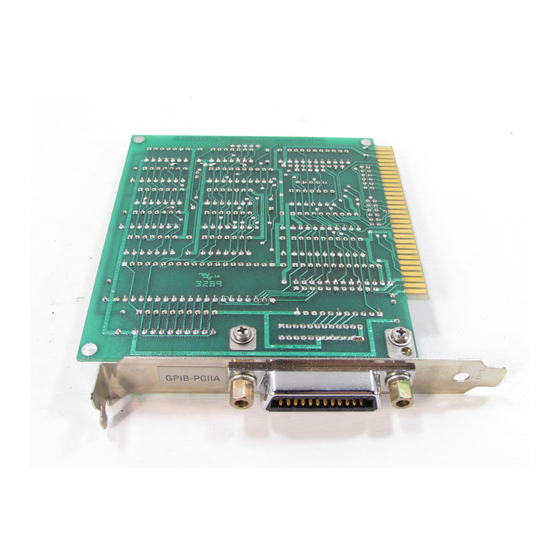
- Page 7 Organization of This Manual This manual is organized as follows: • Chapter 1, Introduction, contains a picture of the GPIB-PCII/IIA interface board, lists the contents of your GPIB-PCII/IIA kit and optional equipment, and contains instructions for unpacking your GPIB-PCII/IIA. •...
- Page 8 Throughout this manual, the word enter is reserved to mean that the commands immediately following the word must be typed into the computer, and then executed by pressing the <Enter> key on the keyboard. PCII/IIA and NI-488.2 MS-DOS viii © National Instruments Corp.
- Page 9 Standard 488-1978, which defines the GPIB input/output personal computer volts alternating current Related Documentation The following document contains information that you may find helpful as you read this manual: The IBM Personal Computer Technical Reference manual © National Instruments Corp. PCII/IIA and NI-488.2 MS-DOS...
- Page 10 To make it easy for you to communicate with us, this manual contains forms for you to complete. These forms are located in Appendix B, Customer Communication, at the back of this manual. PCII/IIA and NI-488.2 MS-DOS © National Instruments Corp.
-
Page 11: Table Of Contents
Contents Chapter 1 Introduction ..................1-1 What Your Kit Should Contain ..........1-3 Optional Equipment..............1-4 Unpacking Your GPIB-PCII/IIA..........1-4 Chapter 2 Installation and Elementary Programming Example ....................2-1 Step 1 – Install the Hardware ..........2-1 Step 2 – Install the Software ..........2-2 Step 3 –... - Page 12 Step 1 – Hardware Configuration ......... A-1 GPIB-PC Mode Selection ..........A-2 Switch and Jumper Settings ......... A-3 7210/9914 Mode Selection........... A-4 Base I/O Address Selection..........A-5 GPIB-PCII Mode ........... A-5 GPIB-PCIIA Mode ........A-7 Possible Conflicts........... A-9 Interrupt Selection ............A-12 Shared Interrupts in GPIB-PCIIA Mode ..A-12 Possible Conflicts...........
- Page 13 GPIB-PC Mode Selection Settings ........A-2 Figure A-3. 7210/9914 Mode Selection Settings ........A-4 Figure A-4. Base I/O Address Switch Settings for GPIB-PCII..... A-6 Figure A-5. Base I/O Address Switch Settings for GPIB-PCIIA..A-7 Figure A-6. Default Interrupt Jumper Setting for GPIB-PCII....A-12 Figure A-7.
-
Page 14: Chapter 1 Introduction
The GPIB-PCII/IIA interface board combines the functionality of the National Instruments GPIB-PCII and GPIB-PCIIA interface boards. This interface board can be configured to function as either a GPIB-PCII or a GPIB-PCIIA, depending on the setting of the configuration switches. Figure 1-1 shows the GPIB-PCII/IIA interface board in PCII mode. - Page 15 Check that the setting of the GPIB-PC mode switch is consistent with the configuration indicated on the identifying label. For information on the GPIB-PC mode switch, refer to Appendix A, Changing the Hardware and Software Configuration Settings, later in this manual. PCII/IIA and NI-488.2 MS-DOS © National Instruments Corp.
-
Page 16: What Your Kit Should Contain
GPIB-PCIIA MS-DOS/Windows Handler, BASICA, QuickBASIC, BASIC, C & Universal 420761-66 and Interfaces 420762-66 • For the GPIB-PCII, one of the following sets of diskettes: - 3.5 in. NI-488.2 Distribution Diskette for GPIB-PCII MS-DOS/Windows Handler, BASICA, QuickBASIC, BASIC, C & Universal Interfaces 422763-66 - Two 5.25 in. -
Page 17: Optional Equipment
*To meet FCC emission limits for this Class B device, you must use a shielded (Type X1 or X2) GPIB cable. Operating this equipment with a non-shielded cable may cause interference to radio and television reception in residential areas. PCII/IIA and NI-488.2 MS-DOS © National Instruments Corp. -
Page 18: Unpacking Your Gpib-Pcii/Iia
Do not remove the board from its plastic bag at this point. 2. Your GPIB-PCII/IIA board is shipped packaged in an antistatic plastic bag to prevent electrostatic damage to the board. Several components on the board can be damaged by electrostatic discharge. -
Page 19: Installation And Elementary Programming Example
Installation and Elementary Programming Example This chapter contains instructions for installing your GPIB-PCII/IIA hardware and NI-488.2 software. It also contains an elementary programming example. Table 2-1 shows the default settings of the GPIB-PCII/IIA interface board. Table 2-1. GPIB-PCII/IIA Default Settings Parameters GPIB-PCIIA... -
Page 20: Step 2 - Install The Software
Remove the top cover or access port to the I/O channel. Remove the expansion slot cover on the back panel of the computer. Insert the GPIB-PCII/IIA board into any unused slot with the IEEE-488 connector protruding out of the back panel. - Page 21 Direct memory access (DMA) is a method of moving data in a computer from one location to another that allows the GPIB-PCII/IIA interface board to operate at top speed. Operating the interface board without using DMA does not limit the functionality of the interface board, but it does limit its speed.
-
Page 22: Step 3 - Test The Software Installation
Step 4 - Install the GPIB Application Monitor Install the GPIB Application Monitor by entering the following command: APPMON The GPIB Application Monitor is a memory-resident program that monitors all GPIB device driver activity in the background. PCII/IIA and NI-488.2 MS-DOS © National Instruments Corp. -
Page 23: Step 5 - Trap Gpib Errors
NI-488.2 routines. This program reads a value from a Fluke 45 multimeter which is at GPIB address 6 and is connected to the PC through GPIB-PCII/IIA board number 0 (gpib0). Refer to the NI-488.2 MS-DOS Software Reference Manual for specific information about each routine. - Page 24 CALL IBWRT(Fluke45%,"*RST; VDC; RANGE 2; TRIGGER 2; *TRG; VAL?") CALL IBRD(Fluke45%,Reading$) PRINT Reading$ CALL IBONL (Fluke45%,0) A more detailed example program is given in Chapter 3, and several more examples are presented in the NI-488.2 MS-DOS Software Reference Manual. PCII/IIA and NI-488.2 MS-DOS © National Instruments Corp.
-
Page 25: Writing An Advanced Program Using Ni-488.2 Routines
The reference number is zero (0) for the first GPIB-PCII/IIA board and one (1) for the second board. If you installed two boards in your computer, and you do not know which board is 0 and which board is 1, run the configuration utility, IBCONF. -
Page 26: Calling Syntax
For this example, it is assumed that you are using GPIB-PCII/IIA interface board number zero (0). In addition, several more of the NI-488.2 routines are used than were shown in Chapter 2. This program finds and identifies all the Listeners on the bus prior to controlling the Fluke 45 instrument. -
Page 27: Step 2 - Initialization
Next find out which, if any, device or devices are connected. This is easily accomplished by using the FindLstn procedure. The first argument is the GPIB-PCII/IIA board number, the second argument is the list of instruments that was created above, the third argument is a list of instrument addresses that the procedure actually found, and the last argument is the maximum number of devices that the procedure may find (that is, it must stop if it reaches the limit). -
Page 28: Step 4 - Identify The Instrument
IEEE-488.2 compatible and can accept the 488.2 identification query, *IDN?. In addition, assume that FindLstn found the GPIB-PCII/IIA interface board at primary address 0 (which is where it is by default) and, therefore, you can skip the first entry in the result array. -
Page 29: Step 5 - Initialize The Instrument
Now that you have found the multimeter, clear it. Initialization of the devices attached to the IEEE-488 bus is accomplished with the DevClear procedure. The first argument is the GPIB-PCII/IIA interface board number. The second argument is the IEEE-488 address of the multimeter. -
Page 30: Step 7 - Trigger The Instrument
The other command, VAL1?, instructs the meter to send the next triggered reading to its IEEE-488.1 output buffer. CALL Send(0, fluke%, "*TRG; VAL?", NLend) IF IBSTA% < 0 THEN CALL gpiberr("Send trigger error") CALL IBONL (0,0) STOP END IF PCII/IIA and NI-488.2 MS-DOS © National Instruments Corp. -
Page 31: Step 8 - Wait For The Instrument To Complete The Measurement
TestSRQ. For this example, there is nothing in particular to do at this point, so you can use the WaitSRQ routine. The first argument to WaitSRQ is the GPIB-PCII/IIA board number. The second argument is a flag returned by WaitSRQ that indicates whether or not SRQ is asserted. -
Page 32: Step 9 - Read The Measurement
REM $INCLUDE: 'C:\GPIB-PC\QBDECL.BAS' DECLARE SUB gpiberr (msg$) DIM instruments% (31) DIM result% (31) DIM Reading AS STRING*30 CALL SendIFC(0) IF IBSTA% < 0 THEN CALL gpiberr("SendIFC(0) error") CALL IBONL (0,0) STOP END IF PCII/IIA and NI-488.2 MS-DOS © National Instruments Corp. - Page 33 END IF NEXT K% PRINT "Did not find the Fluke!" CALL IBONL (0,0) STOP found: CALL DevClear(0, fluke%) IF IBSTA% < 0 THEN CALL gpiberr("DevClear error") CALL IBONL (0,0) STOP END IF © National Instruments Corp. PCII/IIA and NI-488.2 MS-DOS...
- Page 34 CALL gpiberr("Improper status byte") PRINT "Status byte: "; status% CALL IBONL (0,0) STOP END IF CALL Receive(0, fluke%, Reading$, STOPend) IF IBSTA% < 0 THEN CALL gpiberr("Receive error") CALL IBONL (0,0) STOP END IF PCII/IIA and NI-488.2 MS-DOS 3-10 © National Instruments Corp.
-
Page 35: The Error Handling Subroutine
IF IBERR% = ESTB THEN PRINT " ESTB <Status byte lost>" IF IBERR% = ESRQ THEN PRINT " ESRQ <SRQ stuck on> " IF IBERR% = ETAB THEN PRINT " ETAB <Table Overflow> " PRINT "IBCNT="; IBCNT%; " " END SUB © National Instruments Corp. 3-11 PCII/IIA and NI-488.2 MS-DOS... -
Page 36: Compiling And Linking
#include "c:\gpib-pc\decl.h" #define MAVbit 0x10 /* Position of the Message Available bit.*/ char buffer[101]; int loop, m; int num_listeners; double sum; unsigned int instruments[32], result[32], fluke; unsigned int statusByte; int SRQasserted; PCII/IIA and NI-488.2 MS-DOS 3-12 © National Instruments Corp. - Page 37 (loop = 1; loop <= num_listeners; loop++) { Send(0, result[loop], "*IDN?", 5L, NLend); Receive(0, result[loop], buffer, 100L, STOPend); buffer[ibcnt] = '\0'; printf("The instrument at address %d, %d is a %s\n", GetPAD(result[loop]), GetSAD(result[loop]), buffer); © National Instruments Corp. 3-13 PCII/IIA and NI-488.2 MS-DOS...
- Page 38 (0,0); exit(1); Wait for the Fluke to assert SRQ, meaning it is ready with the measurement. WaitSRQ(0, &SRQasserted); if (!SRQasserted) { printf("SRQ is not asserted. The Fluke is not ready.\n"); PCII/IIA and NI-488.2 MS-DOS 3-14 © National Instruments Corp.
- Page 39 = '\0'; printf("Reading : %s\n", buffer); sum = sum + atof(buffer); printf(" The average of the 10 readings is : %f\n", sum/10); sendIFC (0); ibonl (0,0); gpiberr(char *msg) printf ("%s\n", msg); © National Instruments Corp. 3-15 PCII/IIA and NI-488.2 MS-DOS...
-
Page 40: Helpful Hint
488.2 routines, read the NI-488.2 MS-DOS Software Reference Manual for a description of all of the NI-488.2 routines available for the GPIB-PCII/IIA. After reading about these functions and their capabilities, practice using them with your programmable instrument or device in an interactive environment using the IBIC program described in Chapter 6 of the NI-488.2 MS-DOS Software Reference Manual. -
Page 41: Changing Hardware And Software Configuration Settings
Configuration Settings This appendix contains instructions for changing the configuration settings of your GPIB-PCII/IIA interface board. You only need to change the configuration settings if the default settings conflict with another board in your system. Step 1 – Hardware Configuration Figure A-1 shows the location of the GPIB-PCII/IIA configuration jumpers and switches. -
Page 42: Gpib-Pc Mode Selection
Appendix A GPIB-PC Mode Selection The GPIB-PCII/IIA interface board is set at the factory to function as either a GPIB-PCII or a GPIB-PCIIA board. Using the board in its default configuration ensures that the software configuration is consistent with the hardware. To change the GPIB-PC mode of the board, use switch 9 in switch block U2. -
Page 43: Switch And Jumper Settings
Switch and Jumper Settings Table A-1 shows the factory settings and available configurations for the switches and jumpers on the GPIB-PCII/IIA in GPIB-PCII mode. Table A-2 shows the factory settings and available configurations for the switches and jumpers in GPIB-PCIIA mode. -
Page 44: 7210/9914 Mode Selection
Step 2 - Software Configuration at the end of this appendix. 7210/9914 Mode Selection The GPIB-PCII/IIA can emulate many IEEE-488 interface boards that use the TI 9914A GPIB Controller chip as well as the 7210 chip. Use switch 8 in switch block U2 to select either TI 9914A mode or NEC 7210 mode. -
Page 45: Base I/O Address Selection
Base I/O Address Selection GPIB-PCII Mode The GPIB-PCII base I/O address is set using the switches at position U2. The switch block is used to set the address for address lines A3 through A9. The addresses are in a consecutive block of eight beginning on any multiple of 8 between 000 and 3F8 hex. -
Page 46: Figure A-4. Base I/O Address Switch Settings For Gpib-Pcii
Push this side down for logic 0 Binary Hex a. Switch Set to Binary Hex Base I/O Address hex 300 b. Switch Set to Default Setting (Address hex 2B8) Figure A-4. Base I/O Address Switch Settings for GPIB-PCII PCII/IIA and NI-488.2 MS-DOS © National Instruments Corp. -
Page 47: Gpib-Pciia Mode
06E1 12E1 1AE1 1EE1 16E1 82E1 8AE1 8EE1 86E1 92E1 9AE1 9EE1 96E1 a. Switch Set to Base I/O Address hex 2E1 Figure A-5. Base I/O Address Switch Settings for GPIB-PCIIA (continues) © National Instruments Corp. PCII/IIA and NI-488.2 MS-DOS... - Page 48 66E1 6AE1 6EE1 72E1 76E1 7AE1 7EE1 E2E1 E6E1 EAE1 EEE1 F2E1 F6E1 FAE1 FEE1 d. Switches Set to Base I/O Address hex 62E1 Figure A-5. Base I/O Address Switch Settings (continued) PCII/IIA and NI-488.2 MS-DOS © National Instruments Corp.
-
Page 49: Possible Conflicts
When they do surface, the problem can exhibit itself simply as strange behavior. National Instruments has made every effort to select a default base I/O address that will work. However, because of the numerous different interface boards available for use in the PC, it is not possible to select a base I/O address that is guaranteed to work in all systems. - Page 50 2A0 to 2A7 LIM Expanded Memory Card 2A9 to 2AF 2B0 to 2DF PC, AT EGA (alternate) LIM Expanded Memory Card, GPIB-PCII (base) 2B9 to 2BF 2C0 to 2DF AT-GPIB board 0 (default) 2E0 to 2FF AT-GPIB board 1 (default)
- Page 51 Monochrome Display/Parallel Printer Adapter 0 3C0 to 3CF Enhanced Graphics Adapter, VGA 3D0 to 3DF Color/Graphics Monitor Adapter, VGA 3E0 to 3EF 3F0 to 3F7 Diskette Controller 3F8 to 3FF Serial Port 1 (COM1) © National Instruments Corp. A-11 PCII/IIA and NI-488.2 MS-DOS...
-
Page 52: Interrupt Selection
If you use the GPIB-PCII/IIA in GPIB-PCIIA mode and you want to change the interrupt line, you must set switches I0, I1, and I2 in switch set U2 to the line setting in addition to setting the interrupt jumpers. -
Page 53: Figure A-7. Default Interrupt Jumper Setting For Gpib-Pciia
= side you must press down = not used to select the interrupt line Binary Hex Figure A-7. Default Interrupt Jumper Setting for GPIB-PCIIA © National Instruments Corp. A-13 PCII/IIA and NI-488.2 MS-DOS... -
Page 54: Figure A-8. Interrupt Jumper Settings For Gpib-Pciia
= side you must press down = not used to select the interrupt line a. Interrupt Line 6 Selected b. Interrupt Line 5 Selected Figure A-8. Interrupt Jumper Settings for GPIB-PCIIA (continues) PCII/IIA and NI-488.2 MS-DOS A-14 © National Instruments Corp. - Page 55 Appendix A Changing Hardware and Software Configuration Settings c. Interrupt Line 4 Selected d. Interrupt Line 3 Selected e. Interrupt Line 2 Selected Figure A-8. Interrupt Jumper Settings for GPIB-PCIIA (continued) © National Instruments Corp. A-15 PCII/IIA and NI-488.2 MS-DOS...
-
Page 56: Possible Conflicts
When they do surface, the problems can exhibit themselves simply as strange behavior. National Instruments has made every effort to select a default interrupt line that will work. However, because of the numerous different interface boards available for use in the PC, it is not possible to select an interrupt line that is guaranteed to work in all systems. -
Page 57: Dma Channel Selection
Keyboard Controller Output Buffer Full Timer Channel 0 Output DMA Channel Selection The GPIB-PCII/IIA can use DMA channels 1, 2, or 3, or no DMA at all. The DMA channel is selected by the jumper sets labeled DRQ1 through DACK 3 (see Figure A-1). -
Page 58: Figure A-9. Dma Channel Jumper Settings
Changing Hardware and Software Configuration Settings Appendix A Table A-5. DMA Channels for the GPIB-PCII/IIA Signal Lines Channel Acknowledge Request DACK1 DRQ1 DACK2 DRQ2 DACK3 DRQ3 You must position two jumpers to select a DMA channel. One jumper selects the DMA Request line, and the other selects the DMA Acknowledge line. You... -
Page 59: Possible Conflicts
DMA Channel 2 Selected Figure A-9. DMA Channel Jumper Settings (continued) If you do not want to use DMA for GPIB transfers (the GPIB-PCII/IIA alternatively can use programmed I/O transfers), you must logically disconnect the GPIB-PCII/IIA from the DMA lines by selecting NONE for the DMA line when you run IBCONF in Step 2 - Configure the Software later in this chapter. -
Page 60: Shield Ground Configuration
Appendix A Shield Ground Configuration The GPIB-PCII/IIA is set at the factory with the jumper in place to connect the logic ground of the GPIB-PCII/IIA to its shield ground. This configuration minimizes the EMI emitted from a PC equipped with a GPIB-PCII/IIA. -
Page 61: Appendix B Customer Communication
Filling out a copy of the Technical Support Form before contacting National Instruments helps us help you better and faster. National Instruments provides comprehensive technical assistance around the world. - Page 62 National Instruments for technical support helps our applications engineers answer your questions more efficiently. If you are using any National Instruments hardware or software products related to this problem, include the configuration forms from their user manuals. Include additional pages if necessary.
- Page 63 National Instruments software product Version Configuration The problem is List any error messages The following steps will reproduce the problem...
- Page 64 Complete this form each time you revise your software or hardware configuration, and use this form as a reference for your current configuration. Completing this form accurately before contacting National Instruments for technical support helps our applications engineers answer your questions more efficiently. National Instruments Products GPIB-PCII/IIA Hardware •...
- Page 65 • GPIB-PC Handler Type set in IBCONF • Interrupt Level set in IBCONF • DMA Channel set in IBCONF • Base I/O Address set in IBCONF Other Products • Computer Make and Model • Microprocessor • Clock Frequency • Type of Monitor Card Installed •...
- Page 66 Documentation Comment Form National Instruments encourages you to comment on the documentation supplied with our products. This information helps us provide quality products to meet your needs. Title: Getting Started with Your GPIB-PCII/IIA and the ™ NI-488.2 Software for MS-DOS...
- Page 67 Thank you for your help. Name Title Company Address Phone Mail to: Technical Publications National Instruments Corporation 6504 Bridge Point Parkway, MS 53-02 Austin, TX 78730-5039 Fax to: Technical Publications National Instruments Corporation MS 53-02 (512) 794-5678...
Need help?
Do you have a question about the GPIB-PCII and is the answer not in the manual?
Questions and answers