National Instruments GPIB-232CT-A IBCL EPROM Installation Manual
Hide thumbs
Also See for GPIB-232CT-A IBCL EPROM:
- Getting started (41 pages) ,
- Getting started (34 pages) ,
- Getting started (89 pages)
Advertisement
Quick Links
NATIONAL
INSTRUMENTS
The Software is the Instrument
GPIB-232CT-A IBCL EPROM
This guide describes how to replace the factory-installed EPROM that comes
with your GPIB-232CT-A. This kit is meant to be used with the GPIB-CT IBCL
Reference Manual.
The procedures in this guide should be performed only by qualified persons.
This guide contains separate instructions for the AC and DC versions of the
GPIB-232CT-A. Be sure you follow the appropriate instructions for
disassembling and reassembling your GPIB-232CT-A.
Introduction
The Interface Bus Control Language (IBCL) is a powerful, interactive language
that you can use to program the GPIB-232CT-A. You can use IBCL to create
custom applications that are outside the scope of the NI-488.2
firmware that comes with your GPIB-232CT-A. IBCL is intended for
experienced users who require additional functionality and stand-alone capability.
If you want to use IBCL, you must replace the factory-installed EPROM. The
original warranty for your GPIB-232CT-A is still valid if you follow the
directions in this installation guide.
What You Need to Get Started
One of the following boxes:
GPIB-232CT-A (100-120 VAC)
GPIB-232CT-A (220-240 VAC)
GPIB-232CT-A (DC)
GPIB-232CT-A IBCL EPROM
_____________________________
NI-488.2
s a trademark of National Instruments Corporation. Product and
™ i
company names are trademarks or trade names of their respective companies.
320613B-01
© 1993, 1994 National Instruments Corp. All rights reserved.
®
®
Installation Guide
Installation Guide
software and the
™
Sept. 1994
Advertisement

Related Manuals for National Instruments GPIB-232CT-A IBCL EPROM


Summary of Contents for National Instruments GPIB-232CT-A IBCL EPROM
-
Page 1: What You Need To Get Started
GPIB-232CT-A (220-240 VAC) GPIB-232CT-A (DC) GPIB-232CT-A IBCL EPROM _____________________________ NI-488.2 s a trademark of National Instruments Corporation. Product and ™ i company names are trademarks or trade names of their respective companies. 320613B-01 © 1993, 1994 National Instruments Corp. All rights reserved. - Page 2 The following tools: • Phillips screwdriver • 3/16 in. nutdriver • 1/4 in. nutdriver or pliers • Scribe Caution: Most of the circuitry in the GPIB-232CT-A uses advanced CMOS technology and can be damaged by static electricity. Avoid touching any of the components and take any necessary CMOS handling precautions.
- Page 4 Disassembling the GPIB-232CT-A (DC Version) This section describes the disassembly of the DC version of the GPIB-232CT-A. Refer to Figure 2 and complete the following steps to disassemble the GPIB-232CT-A. Note: You may find that organizing the pieces as you disassemble the GPIB-232CT-A simplifies reassembly.
- Page 6 Changing the GPIB-232CT-A EPROM (AC Version) Refer to Figure 3 and complete the following steps to change the GPIB-232CT-A EPROM. Turn the printed wiring board (H) so that the underside is facing upwards. Use the scribe to remove the old EPROM (O) by carefully prying it out of the EPROM socket (P).
- Page 8 Changing the GPIB-232CT-A EPROM (DC Version) Refer to Figure 4 and complete the following steps to change the GPIB-232CT-A EPROM. Turn the printed wiring board (H) so that the underside is facing upwards. Use the scribe to remove the old EPROM (O) by carefully prying it out of the EPROM socket (P).
- Page 10 Reassembling the GPIB-232CT-A (AC Version) This section describes how to reassemble the AC version of the GPIB-232CT-A. The reassembly instructions for the DC version are located in the next section. Refer to Figure 5 and complete the following steps to reassemble the AC version of the GPIB-232CT-A.
- Page 12 Reassembling the GPIB-232CT-A (DC Version) This section describes how to reassemble the DC version of the GPIB-232CT-A. Refer to Figure 6 and complete the following steps to reassemble the DC version of the GPIB-232CT-A. 1. Align the printed wiring board (H) on the lower assembly standoffs (N). Check that the wires that connect the printed wiring board (H) to the DC power jack (R) and the transistor (S) are inside the box and are not being pinched.
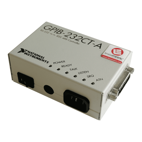
- Page 14 Verifying the EPROM Installation To verify that you have properly installed the EPROM, plug in the unit and power on your GPIB-232CT-A. The POWER indicator should come on immediately. The READY indicator should come on after the GPIB-232CT-A has passed its power-on self test, indicating the unit is ready for operation.
Need help?
Do you have a question about the GPIB-232CT-A IBCL EPROM and is the answer not in the manual?
Questions and answers