
Related Manuals for tousek ST 64


Summary of Contents for tousek ST 64
- Page 1 Connection and installation manual Swing gate control unit ST 64, ST 64A to connect 4 SWING X operators Safety Sensor...
-
Page 2: Table Of Contents
March 2019 This manual is the sole property of the TOUSEK Ges.m.b.H. and may not be made available to competitors. All rights reserved. No part of it may be reproduced without our prior written permission. We will not accept liability for any claims resulting from misprints or errors. This edition of the manual replaces all earlier publications of the same. -
Page 3: General Warning And Safety Notes
• Maintenance and servicing of the complete gate facility has to be carried out according to the gate builder´s/ installer´s instructions. • Check the proper sensitivity setting of the ARS safety reverse system once a month. - 3 - tousek / EN_ST-64_02 / 25. 03. 2020... -
Page 4: General Features, Control Unit Overview, Technical Data
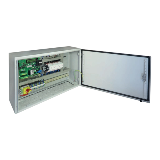
NT power supply (pre-wired) with 1 or 2 motor control boards to control 1 or 2 drop bolts SAFELOCK SCH contactor 1–8 (pre-wired) HS main switch (pre-wired) terminal block on DIN rail (pre-wired) Technical data Swing gate control unit ST 64, ST 64A power supply 230V a.c., +/-10% 50Hz protection class IP54 motor output 4 x 500W, 230V a.c. speed sensor flashing light output 230V AC, 40W photocell output 24V a.c. - Page 5 ST 64A including additional components: traffic light control unit STA 11 page 29–34 For wiring the additional components, please follow optional: the descriptions on the pages listed dropbolt module page 21–22 dropbolt control unit page 21–22 d ropbolt control unit for one dropbolt dropbolt control unit for two dropbolts - 5 - tousek / EN_ST-64_02 / 25. 03. 2020...
- Page 6 For the wiring of additional components, please follow the descriptions on the listed pages. • Connections to motor bolt module and motor bolt control (optional) page 21–22 • Connections to traffic light control STA 11 (built into the ST64A) page 29–34 - 6 - tousek / EN_ST-64_02 / 25. 03. 2020...
-
Page 7: Terminal Assignment, Connection Notes
Terminal assignment KL1, KL2 Swing gate control unit ST 64(A) Terminal blocks (KL1) on the control board (ST) 88 89 88 89 traffic light control board page 29 41 42 43 44 45 46 48 80 81 82 83... -
Page 8: Connection Notes For Swing X Operators
Connection notes operator SWING X Swing gate control unit ST 64 (A) Danger • Before connection work or taking off the housing cover, the power supply has to be turned off ! • Set force adjustments (menu: left left and right leaf) according to your effective safety rules and regulations also follow safety instructions on page 6 ! ... -
Page 9: Adjustments - Overview, Menu Structure
Adjustments - overview Swing gate control unit ST 64 (A) Programming buttons Einstellungen-Übersicht • The adjustment (programming) of the operating parameters is carried out via four programming buttons and the text display. • Before you can start programming, select the language of the display. You can do this by pressing the + or - and choose the language for the menuas and press ENTER. • Note: The language setting can be changed any time by pressing the ESC button for 5s. • The text display informs you on the operating modes, selected menus and adjustment of several parameters. - Page 10 The menu points courtyard lamp and control lamp will only appear on display if in menu „Additional module“ courtyard lamp/control lamp is selected. ENTER Swing gate control unit ST64(A) - 10 - tousek / EN_ST-64_02 / 25. 03. 2020...
-
Page 11: Connections And Adjustments
(FE) is set out of order for reasons of safety. • If the impulse switch is set to DEAD MAN operation, then also all other buttons are in DEAD MAN mode. With the impulse-, or the pedestrian button the gate is opened, with the CLOSE-button it is closed. • IMPORTANT: Do not put into operation in dead man mode. Select only after putting into operation ( page 25), if desired. - 11 - tousek / EN_ST-64_02 / 25. 03. 2020... - Page 12 The stop input has no emergency stop function! - In order to ensure the emergency stop function, provide the supply line with an all-pole disconnecting emergency stop switch, that locks after actuation! - 12 - tousek / EN_ST-64_02 / 25. 03. 2020...
-
Page 13: Safety
Detailed information you will find in the corresponding photocell manual. inner photocell (contact: terminals KL1 45/46) Safety active: to be selected, if inner photocell should be triggered. not active: to be selected, if inner photocell should not be triggered. outer photocell (contact: terminals KL1 45/48) Safety active: to be selected, if outer photocell should be triggered. not active: to be selected, if outer photocell should not be triggered. - 13 - tousek / EN_ST-64_02 / 25. 03. 2020... - Page 14 Tousek RLS 620 as safety device transmitter receiver 12/24V 12/24V NC C NO 24Va.c. Important • Jumper J of transmitter and receiver has to be adjusted in the same way. - 14 - tousek / EN_ST-64_02 / 25. 03. 2020...
- Page 15 active: to be selected if the contact strip (8,2kOhm) of main safety sensing edge 2 should be evaluated. not active: to be selected if the contact strip of main safety sensing edge 2 should not be evaluated radio edge TX310: to be selected if safety sensing edge (8,2kΩ) of main entrance edge 2 should be evaluated with the radio transmission system TX 310. • Connection and detailed information of radio transmission system TX 310 see according manual. - 15 - tousek / EN_ST-64_02 / 25. 03. 2020...
- Page 16 • The photocell self-test can only be deactivated by selecting „not active“. • The deactivation of the self-test function is only permitted if the safety installations correspond to the category 3 ! - 16 - tousek / EN_ST-64_02 / 25. 03. 2020...
-
Page 17: Left Leaf
100% (factory setting) 25–100% adjustable: indicates the partial opening of the gate leaf with closing delay in relation to complete opening width. This adjustment is ONLY adopted in CLOSED Postion. - 17 - tousek / EN_ST-64_02 / 25. 03. 2020... - Page 18 HSK 2 active active outside (HSK 2-term.50/53) HSK 1 inside active inside (HSK 1-term.50/52) Mode HSK 2 inside/outside outside active Limit tolerance Operating logic 20 (factory setting) 3–20 adjustable: indicates the tolerance in the end positions (low value = sensitive behaviour). - 18 - tousek / EN_ST-64_02 / 25. 03. 2020...
-
Page 19: Light / Lamps
During pause time, in opened position or when the gate stops it is illuminated. During the closing movement it flashes rapidly. If the gate is closed, the pilot lamp expires illuminates in open position: Pilot lamp is illuminated as soon as the gate has reached end position open. - 19 - tousek / EN_ST-64_02 / 25. 03. 2020... -
Page 20: Peripherals
0 = open, 1= closed Locking Peripherals e-lock/magnetic clamp: with additional module electric lock/magnetic clamp. motor lock: with additional module motorized locking bar. Motor lock Peripherals OPEN and CLOSE: locking via motorized locking bar in both end positions of the gate. only OPEN: locking via motorized locking bar only in open position. only CLOSE: locking via motorized locking bar only in closed position. - 20 - tousek / EN_ST-64_02 / 25. 03. 2020... - Page 21 • The module (E) is connected with a RJ-plug-in connector to the control unit (ST) in the housing of the ST64(A). • The removable terminals „X“ and „Y“ on the module are wired to the dropbolt control unit (MST) according to the sketch page 22). • After successful connection the dropbolt operation need to be activated in the control unit menu („peripherials/locking“ and „peripherials/dropbolt“) M S T Control unit ST 64(A) incl. components to actuate the dropbolts: (E) dropbolt module (MST) d ropbolt control unit available for 1 or 2 dropbolts RJ-connection ST 64(A) with optional dropbolt module - 21 - tousek / EN_ST-64_02 / 25. 03. 2020...
- Page 22 Limit switch closed, (F1) fuse 0,25A T „T“ with tousek if the bolt is retracted (F2) fuse 4A T controls Jumper „ “ with foreign terminals control units DROPBOLT 2 - 22 - tousek / EN_ST-64_02 / 25. 03. 2020...
-
Page 23: Diagnosis
in this manual. Software version Diagnosis shows the software version and the operator type on the text display Serial number Diagnosis shows the serial number on the text display - 23 - tousek / EN_ST-64_02 / 25. 03. 2020... -
Page 24: Connection Of Radio Receiver
(FE), as shown in the picture. entry mode switch. • For range extension an external antenna FK433 or FK868 • For programming of receiver please see manual for can be connected. radio receiver. IMPORTANT: When operating in traffic light mode with the ST 64A, please plug the radio receiver in the traffic light control board STA 11 page 33 - 24 - tousek / EN_ST-64_02 / 25. 03. 2020... -
Page 25: Initial Operation
Putting into operation Swing gate control unit ST 64 (A) Important: preparation works • Connect control panels, safety devices and motors in compliance with safety regulations. Attention: if no stop switch is connected then the terminals KL1 30/31 have to be bridged. - Page 26 $$$$$$$$$$$$$$$$ mainsafety edge2 $$$$$$$$$$$$$$$$ mainsafety edge2 $$$$$$$$$$$$$$$$ $$$$$$$$$$$$$$$$ active right (term. 50/53) adopt $$$$$$$$$$$$$$$$ mainsafety edge2 $$$$$$$$$$$$$$$$ not active adopt right (term. 50/53) $$$$$$$$$$$$$$$$ mainsafety edge2 $$$$$$$$$$$$$$$$ radio edge TX - 26 - tousek / EN_ST-64_02 / 25. 03. 2020...
- Page 27 $$$$$$$$$$$$$$$$ motor right $$$$$$$$$$$$$$$$ change ? YES $$$$$$$$$$$$$$$$ delay right leaf $$$$$$$$$$$$$$$$ delay right leaf $$$$$$$$$$$$$$$$ $$$$$$$$$$$$$$$$ closing delay adopt $$$$$$$$$$$$$$$$ delay right leaf $$$$$$$$$$$$$$$$ opening delay - 27 - tousek / EN_ST-64_02 / 25. 03. 2020...
- Page 28 • IMPORTANT: With 1 leaf gate installation, only the operator of the actually existing gate leaf must be activated in the main menu, the other one has to be disabled (deactivated) ! (In Main Menu: Left(Right) leaf / Motor / „Motor OFF“) - 28 - tousek / EN_ST-64_02 / 25. 03. 2020...
-
Page 29: Traffic Light Control Board Sta 11
Technical data Traffic light control board STA 11 (in steel housing IP 66 of the operator control unit ST 64A) Power supply 230Va.c., +6/-10%, 50Hz Relay load Red/Green traffic light 230V, max. 60W Article no. 12120360 Optional equipment induction loop detector ISD 6 (2-channels) • pluggable receiver - 29 - tousek / EN_ST-64_02 / 25. 03. 2020... - Page 30 Green display changes to the counter side. When the stop button is triggered, the gate stops moving and only opens again with command by either side. - 30 - tousek / EN_ST-64_02 / 25. 03. 2020...
- Page 31 (rain). fuse 3,15A T With ST 64A no limit switch is necessary: terminals 60/61 have to be wire bridged! 230V max. 60W ST 64A operator control unit - 31 - tousek / EN_ST-64_02 / 25. 03. 2020...
- Page 32 It affects the function of the duration of the green phase, the clearance time, the traffic light at the gate position „closed“ (whether turned off or continuous red) and the traffic light system logic. - 32 - tousek / EN_ST-64_02 / 25. 03. 2020...
- Page 33 STA 11 • For programming of receiver please see manual for radio receiver. STA 11 - 33 - tousek / EN_ST-64_02 / 25. 03. 2020...
- Page 34 PWR (yel- blinking when adju- low) sting / power Rotary switches D1, D2 and DIP in factory setting The Reset button (RES) has 2 functions which can be activated via the different duration of the key pressure: • Adjustment: short key pressure (< 2s), Initialization of all activated loop channels. • Reset: average duration of the key press (> 2s), reset the detector, subsequent initialization of all channels. Insert the board of the induction loop detector on the slot (ISD) of the traffic light control unit STA 11. STA 11 - 34 - tousek / EN_ST-64_02 / 25. 03. 2020...
-
Page 35: Error Analysis
Troubleshooting guide Swing gate control unit ST 64 (A) Error possible reason solution mains voltage missing or control of mains voltage as well as fuse F1 defective of fuse F1 no reaction after emitting a command Display: error stop button check if stop button is connected or bridged properly connection between motor and... - Page 36 Buitenheide 2A/ 1 Tel. +32/ 11/ 91 61 60 your service partner: Fax +32/ 11/ 96 87 05 info@tousek.be Tousek Sp. z o.o. Poland PL 43-190 Mikołów (k/Katowic) Gliwicka 67 Tel. +48/ 32/ 738 53 65 Fax +48/ 32/ 738 53 66 info@tousek.pl...
Need help?
Do you have a question about the ST 64 and is the answer not in the manual?
Questions and answers