
Related Manuals for tousek ST 63


Summary of Contents for tousek ST 63
- Page 1 Connection and installation manual ST 63 control unit for folding and swing gates Safety Sensor...
-
Page 2: Table Of Contents
..........................39 This manual is the sole property of the TOUSEK Ges.m.b.H. and may not be made available to competitors. All rights reserved. No part of it may be reproduced without our prior written permission. We will not accept liability for any claims resulting from misprints or errors. This edition of the manual replaces all earlier publications of the same. -
Page 3: General Warning And Safety Notes
EU and in the individual countries have to be strictly followed. • The TOUSEK Ges.m.b.H. can not be held liable for any claims resulting from disregards of the laws and standards in force during the installation and operation. -
Page 4: Notes, General Characteristics, Function, Technical Data
General ST 63 control unit for folding and swing gates Product features • Suitable for folding/swing gates with the electromechanic • safety system ARS (autom. reversal system) operators SWING X3 TPspeed and SWING X4 LHTP with • operating mode: impulse, automatic, dead man or emergency mode integrated speed sensor (1 leaf or 2 leaves operation possible). -
Page 5: Control, Danger Notes, Warnings - Connection Works
Control unit ST 63 control unit for folding and swing gates Warning • Before connection works or taking off • The product is not suitable for installation in the control cover, the mains switch explosion-hazardous areas. must be turned off! •... -
Page 6: Control Box
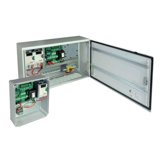
2.1 overview of the control box ST 63 control unit for folding and swing gates control unit in steel housing for 1 or 2 leaf operation FU-1 FU-2 for 1-leaf operation: FU and speed sensor already pre- wired in the factory for right leaf. - Page 7 For wiring optional components, please follow the descriptions on the pages listed. • connection of the dropbolt or the electric lock page 26–27 • connection of the traffic light control unit STA 11 page 33–38 - 7 - tousek / EN_ST-63_02 / 25. 03. 2020...
-
Page 8: Control Board
2.2 control board (ST) ST 63 control unit for folding and swing gates Overview Attention During connection, adjustment and maintenance works please take care, that the electronic circuit board won ́ t be damaged by moisture (rain). display ENTER –... -
Page 9: Terminal Assignment
2.3 Terminal assignment ST 63 control unit for folding and swing gates Danger • Before connection works or taking off the housing cover the power supply has to be turned off ! • Follow safety instructions! ( page 5) ... -
Page 10: Connection Notes For The Operator Swing X-Tp
→ 1 2 3 IMPORTENT! separate tubes or a grounding screw cable channel with partition! green/yellow shield shield MODBUS operators SWING X TP (FU-connection → FU-L or FU-R) - 10 - tousek / EN_ST-63_02 / 25. 03. 2020... - Page 11 Remove the cable sheath at these points! • Take care of the right connection between the metal tongues in the holes and the shield of the motor wire (M). - 11 - tousek / EN_ST-63_02 / 25. 03. 2020...
- Page 12 2.5 Programming ST 63 control unit for folding and swing gates Programming buttons Adjustments - overview • The adjustment (programming) of the operating parameters is carried out with four programming buttons and the display. • Before starting the programming, please choose the language. Use the buttons + or - to choose menu langua- ge and confirm with ENTER.
-
Page 13: Programming, Menu Structure
1,0...6,0s = 3s menu item showed: with traffic mode, without traffic mode, with swing gates, with folding gates ENTER swing / folding gate control ST63 - 13 - tousek / EN_ST-63_02 / 25. 03. 2020... - Page 14 (Electric lock or drop bolt) To deactivate locking, the menu item „locking“ has to be set to „Electric lock/magnetic clamp“ and the menu item „Electric lock“ to „not active“ afterwards. - 14 - tousek / EN_ST-63_02 / 25. 03. 2020...
-
Page 15: Connections And Adjustments
2.6 Connections and adjustments ST 63 control unit for folding and swing gates Danger • Before connection works or taking off the housing cover the power supply has to be turned off ! • Follow safety instructions! ( page 5) ... - Page 16 In emergency mode are the photocells and the safety edges deactivated, but the STOP-switch is still active. Right after deleting the end positions (menu diagnosis→delete positions→yes) emergency mode is NOT possible. - 16 - tousek / EN_ST-63_02 / 25. 03. 2020...
-
Page 17: Photocells
Then the gate opens. If automatic mode is selected the gate closes after the pause time is over. If impluse mode is selected a new CLOSE impulse must be given. - 17 - tousek / EN_ST-63_02 / 25. 03. 2020... - Page 18 OUTSIDE: transmitter receiver Important • To activate the SYNC-function, the SYNC plug-in bridges (J) in both photocell transmitters have to be removed. (see manual LS 41/180). transmitter receiver INSIDE: - 18 - tousek / EN_ST-63_02 / 25. 03. 2020...
- Page 19 Tousek RLS 620 as safety device transmitter receiver 12/24V 12/24V NC C NO 24Va.c. Important • Jumper J of transmitter and receiver has to be adjusted in the same way. - 19 - tousek / EN_ST-63_02 / 25. 03. 2020...
-
Page 20: Safety Edges
(2) right leaf (2) status: not triggered e.g. $$$$$$$$$$$$$$$$ LL1 LL2 RL1 RL2 status: triggered $$$$$$$$$$$$$$$$ status: contact strip not connected or defect status: contact strip deactivated in menu - 20 - tousek / EN_ST-63_02 / 25. 03. 2020... -
Page 21: Left Leaf
OFF, 0,1–9,0s adjustable [increment 0,1]: determines soft stop time in closing direction. Attention With speed adjustment the valid safety regulations and standards have to be strictly followed (Kinetic energy) ! - 21 - tousek / EN_ST-63_02 / 25. 03. 2020... -
Page 22: Operating Mode
1,0–6,0s adjustable [increment 0,1]: ramp time when gate opens. ramp time close Operating mode 3s (factory setting) only with folding gate 1,0–6,0s adjustable [increment 0,1]: ramp time when gate closes. - 22 - tousek / EN_ST-63_02 / 25. 03. 2020... -
Page 23: Light / Lamps
green on both sides: both traffic lights illuminate GREEN in open position, regardless of which side has been given the green request. green on one side: only the traffic light illuminates GREEN in open position, from the side from where the green request has been requested. - 23 - tousek / EN_ST-63_02 / 25. 03. 2020... -
Page 24: Peripherals
OPEN and CLOSE: locking with an electric drop in both end positions of the gate. OPEN only: locking with an electric drop only in the gate open position. CLOSE only: locking with an electric drop only in the gate closed position. - 24 - tousek / EN_ST-63_02 / 25. 03. 2020... - Page 25 Gate in CLOSE-Position Gate in OPEN-Position Gate in CLOSE-Position Gate opens or closes Gate stopped or fault (Gate not in end position) Gate in OPEN-position signal contacts: 0 = open, 1= closed - 25 - tousek / EN_ST-63_02 / 25. 03. 2020...
- Page 26 • ATTENTION: Turn off the power supply! • The module (E) is connected with a RJ-plug-in connector to the control unit (ST) in the housing of the ST 63. • The removable terminals „X“ and „Y“ on the module are...
- Page 27 (TR1, TR2) are already prewired as shown in the illustration below: • motor print boards (M1, M2) are wired to the dropbolt module (E), which is then connected to the ST 63: or one dropbolt: only terminal block „X“...
-
Page 28: Diagnosis
+ and - the single events can be seen: With the protocol beginning Time since the last event: hence the end is shown DAYS HOURS : MINUTES : SECONDS $$$$$$$$$$$$$$$$ T -00 00:00:00.0 $$$$$$$$$$$$$$$$ event Type of event - 28 - tousek / EN_ST-63_02 / 25. 03. 2020... -
Page 29: Connecting The Receiver
Connecting the receiver ST 63 control unit for folding and swing gates Important • Disconnect the power supply. • Plug-in the receiver printed circuit board (E) RS433/868- • With the use of the 2-channel-receiver the second STN1 (1 channel) or RS433/868-STN2 (2 channels) channel takes over the function of the pedestrian into the corresponding slot (FE) as shown in the picture. -
Page 30: Putting Into Operation
Putting into operation ST 63 control unit for folding and swing gates important: preparation works • All electrical installations (control panels, safety devices ...) have to be made in full conformity with the applying rules and laws. Attention: if no stop switch is connected then the terminals KL1 30/31 have to be bridged. - Page 31 RL2 $$$$$$$$$$$$$$$$ safety edge RL2 not active opening active $$$$$$$$$$$$$$$$ $$$$$$$$$$$$$$$$ open close closing active open/close confirm $$$$$$$$$$$$$$$$ safety edge RL2 $$$$$$$$$$$$$$$$ not active e.g. - 31 - tousek / EN_ST-63_02 / 25. 03. 2020...
- Page 32 After giving the impulse to automatically program the end positions, no other impulse must be given. Also the safety devices mustn´t be triggered. This would lead to an interruption of the programming process. - 32 - tousek / EN_ST-63_02 / 25. 03. 2020...
-
Page 33: Optional Traffic Light Control Unit Sta 11
• To implement traffic light function the control unit STA 11 has to be connected with the operator control unit via bus system. Valid for the traffic light mode: • The inputs of the pulse buttons of the ST 63 have no function and the impulse emission is only possible via traffic light board page 35–37 (I-loops, pulse buttons, radio)! - Page 34 Green display changes to the counter side. When the stop button is triggered, the gate stops moving and only opens again with command by either side. - 34 - tousek / EN_ST-63_02 / 25. 03. 2020...
- Page 35 (rain). the 230 lines (supply, motor, signal light) to relocate With ST 63 no limit switch is necessary: terminals 60/61 have to be wire bridged! 230V max. 60W...
- Page 36 These relate to the duration of the green phase and the clearance time, the traffic light at the closed door position (whether or continuous red) and the traffic light logic (both sides / one side green). - 36 - tousek / EN_ST-63_02 / 25. 03. 2020...
- Page 37 (optional) Important • When using a radio receiver in traffic light mode, the receiver is not to plugged into the slot of the ST 63, but into the slot of the traffic light control STA 11 ! • Disconnect the power supply.
- Page 38 • Reset: average duration of the key press (> 2s), reset the detector, subsequent initialization of all channels. Insert the board of the induction loop detector on the slot (ISD) of the traffic light control unit STA 11. STA 11 - 38 - tousek / EN_ST-63_02 / 25. 03. 2020...
-
Page 39: Troubleshooting Guide
ST 63 control unit for folding and swing gates error possible reason solution stop-button not connected or not Stop-button connect or bridge → use display: „Stop-switch triggered“ bridged status display for help display: „inner photocell triggered“ check correct connection hence display: „outer photocell triggered“... - Page 40 Buitenheide 2A/ 1 Tel. +32/ 11/ 91 61 60 your service partner: Fax +32/ 11/ 96 87 05 info@tousek.be Tousek Sp. z o.o. Poland PL 43-190 Mikołów (k/Katowic) Gliwicka 67 Tel. +48/ 32/ 738 53 65 Fax +48/ 32/ 738 53 66 info@tousek.pl...
Need help?
Do you have a question about the ST 63 and is the answer not in the manual?
Questions and answers