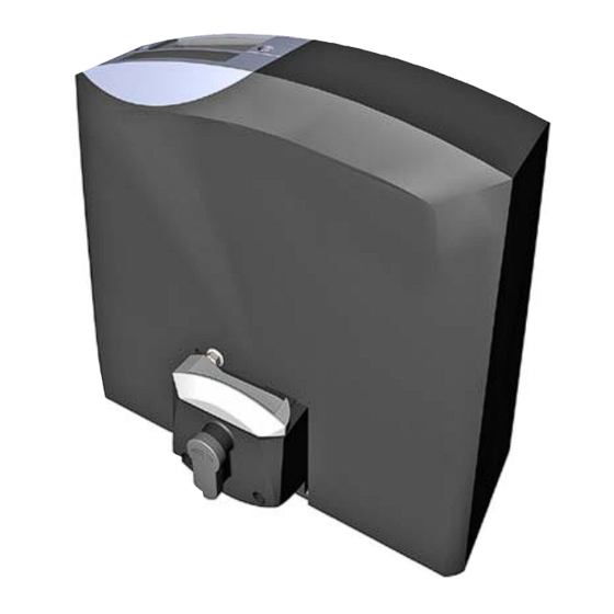
tousek PULL T8 Installation Manual
Sliding gate operators
Hide thumbs
Also See for PULL T8:
- Mounting and installation manual (32 pages) ,
- Mounting and installation manual (36 pages)
Table of Contents
Advertisement
Advertisement
Table of Contents


Need help?
Do you have a question about the PULL T8 and is the answer not in the manual?
Questions and answers