
Related Manuals for ADLINK Technology LEC-iMX6


Summary of Contents for ADLINK Technology LEC-iMX6
- Page 1 LEC-iMX6 (Low Energy Computer on Module) Technical Reference P/N 50-1Z167-1010 Rev 2.00 Advance Technologies. Automate the World.
- Page 2 © Copyright 2014, 2015, 2016 ADLINK Technology, Incorporated Audience This manual provides reference only for computer design engineers, including but not limited to hardware and software designers and applications engineers. ADLINK Technology, Inc. assumes you are qualified to design and implement prototype computer equipment. Preface...
- Page 3 LEC-iMX6 Environmental Responsibility ADLINK is committed to fulfill its social responsibility to global environmental preservation through compliance with the European Union's Restriction of Hazardous Substances (RoHS) directive and Waste Electrical and Electronic Equipment (WEEE) directive. Environmental protection is a top priority for ADLINK. We have enforced measures to ensure that our prod- ucts, manufacturing processes, components, and raw materials have as little impact on the environment as possible.
- Page 4 Preface...
-
Page 5: Table Of Contents
LEC-iMX6 Table of Contents 1 Overview ........................... 1 Block Diagram........................1 Major Components (ICs)......................2 Connectors, LEDs, and Switches ..................3 Specifications......................... 4 Getting Started........................8 2 Hardware ......................... 11 CPU ............................. 11 Memory ..........................11 eMMC NAND Flash ......................11 3 Interfaces ........................ - Page 6 5 Power and System Management .................. 26 SEMA Utility ........................26 On-Board Power Supply ..................... 26 System States ........................26 External Power Button ......................26 Reset-In Signal........................26 External Battery........................26 Appendix A Technical Support ..................27...
-
Page 7: Overview
LEC-iMX6 Overview This initial manual version presents a general overview of the LEC-iMX6. After reviewing this document you should understand the following features of the LEC-iMX6. Functional Block Diagram Major Components (ICs) and Connectors (Locations and Descriptions) Specifications ... -
Page 8: Major Components (Ics)
1.2 Major Components (ICs) Table 1-1 lists the major integrated circuits on the LEC-iMX6, including a brief description of each IC. Figure 1-2 and Figure 1-3 show the locations of the major ICs. Table 1-1: Major Integrated Circuit Descriptions and Functions Chip Type Mfg. -
Page 9: Connectors, Leds, And Switches
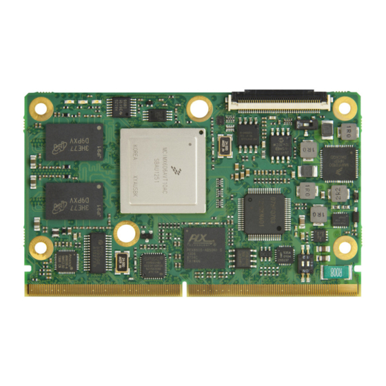
LEC-iMX6 Key: - DDR3L SDRAM U10 - DDR3L SDRAM U16 - eMMC, NAND Flash - Pin 1 Figure 1-3: Component Locations (Bottom Side) 1.3 Connectors, LEDs, and Switches Table 1-2 describes the connectors, LEDs, and switches shown in Figure 1-4. -
Page 10: Specifications
Key: - SMARC Connector - DB40 Debug Connector LED1 - System Status, Blue LED2 - Power On, Green LED3 - Watchdog Activity, Red - U-BOOT_Select - Pin 1 J1 1 Figure 1-4: Connector, LED, and Switch Locations (Top Side) 1.4 Specifications 1.4.1 Physical Specifications Table 1-3 lists the physical dimensions of the module. - Page 11 LEC-iMX6 1.4.2 Mechanical Specifications Figure 1-5: Mechanical Dimensions (Top Side) NOTE: All dimensions are given in millimeters. Overview...
- Page 12 1.4.3 Power Specifications Table 1-4 provides the power requirements for this module. Table 1-4: Power Supply Requirements 800MHz Parameter Characteristics Input Type +3V to +5.25V Regulated DC voltage In-rush Current @5V: • Solo: 443mA • Dual Lite: 456mA • Dual: 794mA •...
- Page 13 1.4.5 Thermal/Cooling Requirements The LEC-iMX6 is designed to operate at its maximum CPU speed and requires a thermal solu- tion. ADLINK offers one cooling option described in Table 1-6. CAUTION: The optional heat spreader plate requires another form of cooling, such as a fan. A heat spreader plate is not a complete thermal solution for the LEC-iMX6.
-
Page 14: Getting Started
1.5.1 Configure boot select jumpers Before starting up the LEC-iMX6, the boot select jumpers on the LEC-BASE baseboard must be configured to correspond with the storage location of the U-Boot boot loader. This section also discusses boot requirements for the Operating System. - Page 15 To ensure U-Boot will run a Linux image from the corresponding boot device, perform the follow- ing steps. 1. Make a serial connection between the COM1 port of the LEC-iMX6 target and a host computer. 2. Open a terminal program with settings 115200 Baud, 8N1. The following screen appears.
- Page 16 edit bootcmd run boot_usb save Note: You need to enter “save” after making a change, or the new setting will be lost after the next boot. Overview...
-
Page 17: Hardware
Hardware 2.1 CPU The LEC-iMX6 product family offers four standard models of the Freescale™ i.MX6 CPU: the i.MX 6Solo (1 core, 2 displays, no SATA), the i.MX 6Dual (2 cores, 3 displays, SATA), the i.MX 6DualLite (2 cores, 2 displays, no SATA), and the i.MX 6Quad (4 cores, 3 displays, SATA). -
Page 18: Interfaces
3.1 Parallel LCD Video The Parallel LCD interface on the LEC-iMX6 can be used in 18-Bit or 24-Bit modes at up to 225 Mpixels/sec. The voltage level of the LCD interface is 1.8V. -
Page 19: Hdmi (High-Definition Multimedia Interface)
The voltage level of the PCAM interface is 1.8V. 3.5 Camera MIPI-CSI The LEC-iMX6 brings out signals for an MIPI CSI-2 serial camera interface. This serial camera port supports up to 1000 Mbps/lane in 1/2-lane mode. The voltage level of the MIPI CSI-2 interface complies with the MIPI CSI specification. -
Page 20: Usb 2.0 Ports
3.8 USB 2.0 Ports The LEC-iMX6 provides two host USB ports and one OTG port. The two host ports are provided from a 4-port USB HUB. All Ports are fully compliant with the USB 2.0 Specification. 3.9 SATA Only the Dual and Quad variants of the LEC-iMX6 module provide a SATA interface. The SATA interfaces on the Dual and Quad models comply with the following specifications. -
Page 21: Serial (Uart)
Four parallel data lines comprise the SD/SDIO interface, supporting SD Card sockets. The LEC-iMX6 provides a 4-bit transfer mode at the SMARC connector using the SDIO pins and the SD2 interface of the i.MX 6 CPU. The following modes can be selected for data transfer: SD/SDIO full speed mode (up to 25 MHz) ... -
Page 22: Emmc Interface
8-bit wide eMMC interface at the SMARC connector (pins S26-S33.) 3.18 GPIO The LEC-iMX6 provides 12 GPIO signals. Seven signals (GPIO 4, 5, 6, 8, 9, 10, 11) are gener- ated by the 9535A GPIO expander, and the remaining five signals (0, 1, 2, 3, and 7) originate from the iMX6 CPU and are designated for CAM0 and CAM1 (PWR and RST). -
Page 23: Interface Signals
LEC-iMX6 Interface Signals 4.1 SMARC Interface Table 4-1 provides the pin signals for the SMARC P-S connector. Refer to the SMARC specifica- tion at http://www.sget.org/standards/smarc.html for definitions of the SMARC signals. Table 4-1: SMARC P-S Connector (J1) Signal Descriptions Pin #... - Page 24 Table 4-1: SMARC P-S Connector (J1) Signal Descriptions (Continued) GBE_MDI2+ (Bi-directional transmit/ receive pair 2 to magnetics [Media Dependent Interface]) GBE_LINK_ACT# (Link / Activity SDMMC_D0 (bidirectional, 8-bit data path; Indication LED Driven low on Link [10, may be used for 4- and 1-bit wide eMMC 100 or 1000 mbps] Blinks on Activity;...
- Page 25 LEC-iMX6 Table 4-1: SMARC P-S Connector (J1) Signal Descriptions (Continued) I2C_GP_CK (I2C General Purpose clock signal) SATA0_TX+ (Differential SATA 0 transmit I2C_GP_DAT (I2C General Purpose data data Pair; 0.1 uF 0402 capacitor on signal) module) SATA0_TX- (Differential SATA 0 transmit Not connected data Pair;...
- Page 26 Table 4-1: SMARC P-S Connector (J1) Signal Descriptions (Continued) AFB_DIFF2- (maps to MLB_SN [Media Local Bus_Signal Negative] on the SOC) USB2+ (Differential USB2 data pair) USB2- (Differential USB2 data pair) AFB_DIFF3+ (maps to MLB_DP [Media Local Bus_Data Positive] on the SOC) USB2_EN_OC# (Pulled low by Module AFB_DIFF3- (maps to MLB_DN [Media OD driver to disable USB2 power.
- Page 27 LEC-iMX6 Table 4-1: SMARC P-S Connector (J1) Signal Descriptions (Continued) PCIE_A_TX+ (Differential PCIe Link A PCIE_B_TX+ (Differential PCIe Link B transmit data pair 0. Series coupling transmit data pair 0. Series coupling caps capacitors are on the Module. 0.1 uF 0402...
- Page 28 Table 4-1: SMARC P-S Connector (J1) Signal Descriptions (Continued) P107 HDMI_CEC (Not Supported) S108 LCD_D14 (8-bit GRN color data - 18-bit display implementations leave the two LS bits (D8, D9) not connected) P108 CAM0_PWR# (Camera 0 Power Enable, S109 LCD_D15 (8-bit GRN color data - 18-bit active low output) display implementations leave the two LS bits (D8, D9) not connected)
- Page 29 LEC-iMX6 Table 4-1: SMARC P-S Connector (J1) Signal Descriptions (Continued) P127 RESET_IN# (Reset input from Carrier S128 LVDS1+ (LVDS LCD data channel board. Carrier drives low to force a differential pair) Module reset, floats the line otherwise. Pulled up on Module. Driven by OD part on Carrier.)
- Page 30 Table 4-1: SMARC P-S Connector (J1) Signal Descriptions (Continued) P147 VDD_IN (Module power input voltage - S148 LID# (Lid open/close indication to Module. 3.0V min to 5.25V max) Low indicates lid closure, which system may use to initiate a sleep state. Carrier to float the line in inactive state.
-
Page 31: Debug (Db40)
LEC-iMX6 Table 4-1: SMARC P-S Connector (J1) Signal Descriptions (Continued) P156 VDD_IN (Module power input voltage - S157 TEST# (Held low by Carrier to invoke 3.0V min to 5.25V max) Module vendor specific test function(s). Pulled up on Module. Driven by OD part on Carrier.) - Page 32 Table 4-2: Debug Interface Signals (CN2) (Continued) SPI_U-BOOT_CS1# SPI Program SPI_U-BOOT_CS0# SPI Program VCC_SPI_IN SPI Program NOTE: The gray table cells denote ground. Power and System Management 5.1 SEMA Utility Under the management of the BMC chip (Board Management Controller), the SEMA utility (Smart Embedded Management Agent) provides system control and failure protection—count- ing, monitoring, and measuring hardware and software events, from which the SOC can trigger corrective commands.
- Page 33 LEC-iMX6 Appendix A Technical Support ADLINK Technology, Inc. provides a number of methods for contacting Technical Support listed in Table A-1 below. Requests for support through Ask an Expert are given the highest priorities, and usually will be addressed within one working day.
- Page 34 +49 (0) 991 290 94 – 10 Fax: +49 (0) 991 290 94 - 29 Email: emea@adlinktech.com ADLINK Technology, Inc. (French Liaison Office) Address: 6 allée de Londres, Immeuble Ceylan 91940 Les Ulis, France Tel: +33 (0) 1 60 12 35 66...
- Page 35 LEC-iMX6 Table A-1: Technical Support Contact Information (Continued) ADLINK Technology Singapore Pte. Ltd. (Indian Liaison Office) Address: #50-56, First Floor, Spearhead Towers Margosa Main Road (between 16th/17th Cross) Malleswaram, Bangalore - 560 055, India Tel: +91-80-65605817, +91-80-42246107 Fax: +91-80-23464606 Email: india@adlinktech.com...
Need help?
Do you have a question about the LEC-iMX6 and is the answer not in the manual?
Questions and answers