Stryker Medical Renaissance Series Maintenance Manual
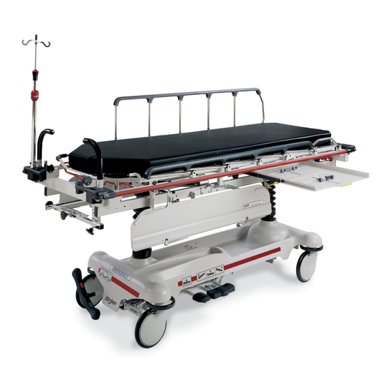
Head/neck surgery bed
Hide thumbs
Also See for Renaissance Series:
- Maintenance manual (123 pages) ,
- Operation manual (19 pages) ,
- Maintenance manual (93 pages)

Subscribe to Our Youtube Channel
Related Manuals for Stryker Medical Renaissance Series


Summary of Contents for Stryker Medical Renaissance Series
- Page 1 IMPORTANT File in your maintenance records Renaissance Series 1067 Head/Neck Surgery Bed MAINTENANCE MANUAL For Parts or Technical Assistance 1–800–327–0770...
-
Page 2: Table Of Contents
Table of Contents Introduction Specifications ..................Warning / Caution / Note Definition . -
Page 3: Introduction
Introduction INTRODUCTION This manual is designed to assist you with the operation and maintenance of the 1067 Head/Neck Surgery Bed. Read it thoroughly before using the equipment or beginning any maintenance on it. SPECIFICATIONS Maximum Weight Capacity 500 pounds Overall Bed Length/Width 84”/28.25”... -
Page 4: Preventative Maintenance
Preventative Maintenance CLEANING 1. Hand wash all surfaces of the bed with warm water and mild detergent. Dry thoroughly. 2. Clean Velcro AFTER EACH USE. Saturate Velcro with disinfectant and allow disinfectant to evaporate. (Appropriate disinfectant for nylon Velcro should be determined by the hospital.) NOTE Quaternary Germicidal Disinfectants, used as directed, and/or Chlorine Bleach products, typically 5.25% So- dium Hypochlorite in dilutions ranging between 1 part bleach to 100 parts water, and 2 parts bleach to 100... -
Page 5: Service Information
Service Information PEDAL LINKAGE ADJUSTMENT – DUAL SIDE CONTROL BASE Required Tools: 3/32 Hex Allen Wrench 7/16 Open End Wrench 1/2 Open End Wrench (2) Wooden blocks (10 – 12 inches in length) Adjustment Procedure: 1. Pump the litter up to full height. 2. -
Page 6: Pedal Linkage Adjustment - Dual End Control Base
Service Information PEDAL LINKAGE ADJUSTMENT – DUAL END CONTROL BASE Required Tools: 7/16 Open End Wrench 1/2 Open End Wrench (2) Wooden Blocks (10 – 12 inches in length) Adjustment Procedure: 1. Pump the litter up to full height. 2. Lift the base hood, separating the hood from the base frame. Using the wooden blocks, support the base hood. -
Page 7: Caster Assembly Replacement
Service Information CASTER ASSEMBLY REPLACEMENT* Required Tools: 1/8 Roll Pin Punch Drill with 1/8 inch Drill Bit Flat Punch (any size larger than 1/8) Hammer Needle Nose Pliers Floor Jack 3/4 Inch Wrench (2) Wooden Blocks (10 – 12 inches in length) 1 Inch Wrench Torque Wrench (w/ Ft. -
Page 8: Caster Cover Installation And Removal
Service Information CASTER COVER INSTALLATION AND REMOVAL Looking through the larger of the two side cut–outs, align cover with axle nut or bolt head, as shown. Double Prongs Push down on the opposite side of the cover until single prong engages with caster horn. Single Prong Top View (Cut–Away) Properly Attached... -
Page 9: Hydraulic System Troubleshooting
Service Information HYDRAULIC SYSTEM TROUBLESHOOTING NOTE Be sure the pedal linkage has been adjusted properly before beginning service on the jacks (see page 4 or page 5). PROBLEM/SYMPTOM SOLUTION Jack will not raise to full height. Add hydraulic fluid (see p.9). Check for leaks. Jack will not hold in raised position. -
Page 10: Checking Hydraulic Fluid Level
Service Information CHECKING HYDRAULIC FLUID LEVEL Required Tools: 3/8 Open End Wrench 3/4 Open End Wrench Procedure: WARNING To avoid personal injury or damage to the stretcher, remove the litter and the base hood before beginning service on the jacks. 1. -
Page 11: Jack Descent Rate Adjustment
Service Information JACK DESCENT RATE ADJUSTMENT Required Tools: Screwdriver (2) Wooden Blocks (10 – 12 inches in length) Adjustment Procedure: 1. Pump the litter up to full height. 2. Lift the base hood, separating the hood from the base frame. Using the wooden blocks, support the base hood. -
Page 12: Hydraulic Check Valve Replacement
Service Information HYDRAULIC CHECK VALVE REPLACEMENT Required Tools: 3/8 Open End Wrench Stiff Wire (with bent, pointed end) Small Needle Nose Pliers 3/4 Open End Wrench Torque Wrench (with Ft. Lbs. adjust.) 7/32 Hex Allen Wrench 1/2 Inch Diameter Rod Replacement of Valve #1 WARNING To avoid personal injury or damage to the stretcher, remove the litter and the base hood before beginning... -
Page 13: Replacement Of Valve #2
Service Information HYDRAULIC CHECK VALVE REPLACEMENT (CONT’D) Replacement of Valve #2 WARNING To avoid personal injury or damage to the stretcher, remove the litter and the base hood before beginning service on the jacks. Lower the jack rod completely to relieve the pressure on the pump piston side of the jack. -
Page 14: Brake Adjustment
Service Information BRAKE ADJUSTMENT Required Tools: 3/32” Hex Allen Wrench Pry Bar Thread ”Locktite” BASE LUBRICATION Do not grease area shown. 1. Lubricate brake adjuster rod around area shown with MPG–2 grease or equivalent. - Page 15 1067–1–10 Side Control Base Assembly...
-
Page 16: Brake Adjuster Assembly
1067–1–10 Side Control Base Assembly Item Part No. Part Name Qty. Item Part No. Part Name Qty. 1210–1–104 Pump Pedal Link Ass’y 715–1–140 Raufilam Braid Tubing (Page 27.1) Jack Assembly 1210–1–120 Base Weldment 11–262 Flat Washer 715–2–20 Caster Assembly 3–62 Hex Hd. - Page 17 1067–1–10 Side Control Base Assembly...
- Page 18 715–1–108 Pedal Base Assembly, Pump Item Part No. Part Name Qty. 715–1–83 Pedal Ass’y Weldm’t, Pump 715–1–126 Side Control Pedal Pad 81–44 Bearing, Bronze NOTE Apply plastic adhesive to the mating surfaces of item B prior to assembly.
- Page 19 715–1–109 Pedal Base Assembly, Left Item Part No. Part Name Qty. 715–1–98 Release Ped. Wldmt., Hd. Lt. 721–40–25 Pedal 715–1–110 Pedal Base Assembly, Head End, Right Item Part No. Part Name Qty. 715–1–97 Release Pedal Weldment 721–40–25 Pedal NOTE Apply plastic adhesive to the mating surfaces of item B prior to assembly.
- Page 20 1067–2–10 End Control Base Assembly...
- Page 21 1067–2–10 End Control Base Assembly Item Part No. Part Name Qty. Item Part No. Part Name Qty. 3–3 Hex Hd. Cap Screw 716–1–61 Pedal Shaft 3–62 Hex Hd. Cap Screw 716–1–71 Release Rod Ass’y 3–85 Hex Hd. Cap Screw 716–1–75 Release Rod 8–17 Soc.
- Page 22 1067–2–10 End Control Base Assembly...
- Page 23 716–1–263 End Control Brake Pedal Assembly, Foot Item Part No. Part Name Qty. 716–1–275 Brake Pedal 716–1–262 Brake Rod Ass’y, Ft. End 716–1–269 End Control Brake Pedal Assembly, Head Item Part No. Part Name Qty. 716–1–275 Brake Pedal 716–1–267 Brake Rod Ass’y, Welded NOTE Apply plastic adhesive to the mating surfaces of item A prior to assembly.
- Page 24 End Control Pump Pedal Assembly, Head Assembly part number 716–1–292 Item Part No. Part Name Qty. 716–1–285 Pump Pivot, Head End 26–12 Roll Pin 716–1–290 Pump Ped. Wldmt., Head 721–40–25 Pedal End Control Pump Pedal Assembly, Foot Assembly part number 716–1–288 Item Part No.
- Page 25 715–1–150 Brake Adjuster Assembly Item Part No. Part Name Qty. 715–1–62 Threaded Stud Assembly 14–4 Nylon Washer 715–1–180 Bearing 28–8 Retaining Ring...
- Page 26 715–1–213 Brake Cam Assembly Item Part No. Part Name Qty. 715–1–221 Brake Cam 16–59 Fiberlock Nut 8–21 Soc. Hd. Cap Screw 715–1–173 Brake Connecting Link...
-
Page 27: Jack Assembly
715–1–310* Jack Assembly Item Part No. Part Name Qty. Item Part No. Part Name Qty. 45–904 O–Ring 45–110 O–Ring 715–1–340 Cap Assembly 388–1–38 Plug 390–1–243 Gasket 715–1–322 Reservoir 715–1–323 Actuator Cylinder 390–1–244 Gasket 715–1–325 Actuator 390–1–238 Gasket, Actuator 45–14 O–Ring (Page 27) Jack Base Assembly 926–20–161... - Page 28 715–1–300 Jack Base Assembly, Foot Control Item Part No. Part Name Qty. Item Part No. Part Name Qty. 715–1–312 Base, Machined 45–110 O–Ring 715–1–308 Base Plug 715–1–328 Piston Wear Ring 715–1–306 14–50 Bearing Retainer 28–8 Snap Ring 715–1–327 Cylinder Wear Ring 390–2–176 Washer 715–1–316...
- Page 29 715–270–10 Jack Assembly Item Part No. Part Name Qty. Item Part No. Part Name Qty. 45–904 O–Ring 45–110 O–Ring 715–1–340 Cap Assembly 388–1–38 Plug 390–1–243 Gasket 715–1–322 Reservoir 715–1–323 Actuator Cylinder 390–1–244 Gasket 715–1–325 Actuator 390–1–238 Gasket, Actuator 45–14 O–Ring (page 27.2) Jack Base Assembly 926–20–161...
-
Page 30: Jack Base Assembly
715–270–5 Jack Base Assembly Item Part No. Part Name Qty. Item Part No. Part Name Qty. 1210–70–12 Jack Base 45–110 O–Ring 1210–70–13 Base Plug 715–1–328 Piston Wear Ring 715–270–1 14–50 Bearing Retainer 45–966 O–Ring 715–1–327 Cylinder Wear Ring 38–311 Compression Spring 715–1–316 Pump Cylinder 45–006... - Page 31 2020–46–220 Steering Caster Assembly Item Part No. Part Name Qty. 946–1–279 Caster Assembly 1000–59–10 Latch Ass’y, Steer Caster...
-
Page 32: Fifth Wheel Assembly
715–1–25 Fifth Wheel Assembly Item Part No. Part Name Qty. 715–1–339 Fifth Wheel Pivot Assembly 715–1–17 Fifth Wheel Bushing 16–11 Flexlock Nut 715–1–15 Spring 715–1–13 Fifth Wheel Bracket 16–12 Flexlock Nut 390–1–54 Wheel 3–31 Hex Head Cap Screw 3–82 Hex Head Cap Screw... -
Page 33: End Control Stretcher Base Labeling Assembly
End Control Stretcher Base Labeling Assembly Item Part No. Part Name Qty. 946–1–60 Stryker Logo Label 1001–100–1 Hood 921–1–252 Serial Number Tag 29–9 Dual Lock (not shown) 1067–1–17 Specification Label 29–7 Dual Lock (not shown) -
Page 34: End Control Stretcher Graphics
End Control Stretcher Graphics Color Item A Control Label, Head Item B Control Label, Foot Item C Stripe Label 1001–800–11 1001–800–12 1001–800–13 PURPLE 1001–800–21 1001–800–22 1001–800–23 GREEN 1001–800–31 1001–800–32 1001–800–33 GRAY 1001–800–41 1001–800–42 1001–800–43 TEAL 1001–800–51 1001–800–52 1001–800–53 PINK 1001–800–61 1001–800–62 1001–800–63 BLUE... -
Page 35: Side Control Stretcher Graphics
Side Control Stretcher Graphics Color Item A Control Label, Right Item B Control Label, Left 1068–702–111 1068–702–112 PURPLE 1068–702–121 1068–702–122 GREEN 1068–702–131 1068–702–132 GRAY 1068–702–141 1068–702–142 TEAL 1068–702–151 1068–702–152 PINK 1068–702–161 1068–702–162 BLUE 1068–702–171 1068–702–172 30.2... -
Page 36: Side Control Stretcher Base Labeling Assembly
Side Control Stretcher Base Labeling Assembly Item Part No. Part Name Qty. 721–31–45 Brake/Steer Label, Hd. 741–1–145 Brake/Steer Label, Ft. 1068–1–135 Hood 921–1–252 Serial Number Tag 29–9 Dual Lock (not shown) 25–77 Pop Rivet 1067–1–17 Specification Label 715–1–176 Oxygen Bottle Holder 11–16 Washer 946–1–60... -
Page 37: Litter Assembly, Manual Fowler, Stationary Foot End
966–32 Litter Assembly, Manual Fowler, Stationary Foot End Item Part No. Part Name Qty. (page 33) Litter Frame Assembly (page 34) Manual Fowler Assembly 966–34–40 Pivot Sleeve 966–34–41 Pivot 52–17 Spacer 16–36 Nylock Hex Nut 8–32 Shoulder Bolt 966–1–45 Protective Strip 16–5 Conelock Hex Nut 3–17... -
Page 38: Basic Frame Assembly, Stationary Foot End
966–1–17 Basic Frame Assembly, Stationary Foot End Item Part No. Part Name Qty. Item Part No. Part Name Qty. 946–1–37 Corner, Head, Left 946–1–30 Ft. End Litter Support 948–1–38 Corner, Head, Right 4–52 Soc. Hd. Cap Screw 37–30 Hole Plug 946–1–36 Supt. -
Page 39: Manual Fowler Assembly
966–32–60 Manual Fowler Assembly Item Part No. Part Name Qty. 966–32–62 Fowler Tube 966–32–63 Fowler Skin 966–32–61 Manual Fowler Pivot 966–1–30 Fowler Crossbar 2–15 Round Hd. Mach. Screw 16–2 Fiberlock Nut 25–55 Pop Rivet 393–53–20 Strap Anchor 25–56 Pop Rivet 14–2 Nylon Washer 3–5... - Page 40 966–35 Litter Ass’y, Crank Fowler, Crank Knee Gatch Item Part No. Part Name Qty. Item Part No. Part Name Qty. (page 36) Litter Frame Assembly 8–32 Shoulder Bolt (page 37) Fowler Assembly 52–17 Spacer 966–34–40 Pivot Sleeve 16–16 Fiberlock Hex Nut 966–34–41 Pivot 25–75...
-
Page 41: Basic Frame Assembly, Crank Knee Gatch
966–1–18 Basic Frame Assembly, Crank Knee Gatch Item Part No. Part Name Qty. Item Part No. Part Name Qty. 946–1–37 Corner, Head, Left 966–31–11 Crank Support Ass’y 948–1–38 Corner, Head, Right 4–52 Soc. Hd. Cap Screw 966–31–19 Fowler Track, Left 946–1–36 Supt. -
Page 42: Crank Fowler Assembly
966–33–10 Crank Fowler Assembly Item Part No. Part Name Qty. 966–32–62 Fowler Tube 966–32–63 Fowler Skin 966–33–11 Fowler Pivot 966–1–30 Fowler Crossbar 2–15 Round Hd. Mach. Screw 16–2 Fiberlock Nut 25–55 Pop Rivet 393–53–20 Strap Anchor 25–56 Pop Rivet... -
Page 43: Fowler Crankscrew Assembly
966–33–15 Fowler Crankscrew Assembly Item Part No. Part Name Qty. 958–1–545 Crank Disc 1550–1–16 Crank Handle 26–166 Groove Pin 26–14 Roll Pin 81–176 Thrust Washer 81–175 Thrust Bearing 81–174 Thrust Washer 938–1–175 Bearing Assembly 938–1–177 Knob 378–24–29 Shoulder Bolt 16–6 Kep Nut 966–33–16 Fowler Screw... -
Page 44: Knee Gatch Assembly
966–34–16 Knee Gatch Assembly Item Part No. Part Name Qty. 926–34–30 Lever Assembly 966–34–45 Calf Section Tube 966–34–23 Calf Section Skin 926–34–22 Thigh Section Tube 926–34–17 Thigh Section Skin 946–34–26 Guide 389–32–13 Hinge 25–55 Pop Rivet 25–76 Pop Rivet 22–7 Drive Screw 393–53–20 Strap Anchor... -
Page 45: Knee Gatch Crankscrew Assembly
966–34–15 Knee Gatch Crankscrew Assembly Item Part No. Part Name Qty. 958–1–545 Crank Disc 1550–1–16 Crank Handle 26–166 Groove Pin 26–14 Roll Pin 81–176 Thrust Washer 81–175 Thrust Bearing 81–174 THrust Washer 938–1–175 Bearing Assembly 26–11 Roll Pin 966–34–37 Label 938–1–177 Knob 378–24–29... - Page 46 966–72 Litter Ass’y, Articulating Man. Fowler, Stat. Ft. End Item Part No. Part Name Qty. Item Part No. Part Name Qty. (page 33) Litter Frame Assembly 25–77 Pop Rivet (page 42) Art. Man. Fowler Ass’y 25–40 Pop Rivet 966–34–40 Pivot Sleeve 966–32–41 Skin Support Angle, Lt.
-
Page 47: Articulating Manual Fowler Assembly
966–70–10 Articulating Manual Fowler Assembly Item Part No. Part Name Qty. Item Part No. Part Name Qty. 966–70–18 Fowler Side Tube 14–4 Washer 966–70–17 Fowler Head Tube 16–5 Conelock Nut 966–70–35 Art. Fowler Skin Set 38–171 Compression Spring 966–70–36 Spacer 966–51–19 Modified Wedge Lock 966–33–11... - Page 48 966–75 Litter Ass’y, Articulating Crank Fowler,Crank Gatch Item Part No. Part Name Qty. Item Part No. Part Name Qty. (page 36) Litter Frame Assembly 8–32 Shoulder Bolt (page 44) Art. Crank Fowler Ass’y 52–17 Spacer 966–34–40 Pivot Sleeve 16–16 Fiberlock Hex Nut 966–34–41 Pivot 25–75...
-
Page 49: Articulating Crank Fowler Assembly
966–71–10 Articulating Crank Fowler Assembly Item Part No. Part Name Qty. Item Part No. Part Name Qty. 966–70–18 Fowler Side Tube 966–70–27 Bar Clamp 966–70–17 Fowler Head Tube 21–73 Set Screw 966–70–35 Art. Fowler Skin Set 3–5 Hex Hd. Cap Screw 966–70–36 Spacer AC 16–5... - Page 50 966–26–10, 11 Folddown Siderail Assembly, Left & Right (Left Side is Shown) Item Part No. Part Name Qty. 919–26–40 Top Rail 37–44 Modified End Plug 25–61 Semi–Tubular Rivet 919–26–37 Upright 919–26–36 Latch Upright 919–26–39 Latch Assembly 4–49 H. Soc. But. Hd. Cap Screw 946–26–35 Pivot Sleeve 52–14...
- Page 51 966–26–30 Siderail & Bumper Assembly, Left Item Part No. Part Name Qty. (page 45) Siderail Assembly 966–26–47 Bumper, Left 966–26–41 14–19 Washer 4–56 Soc. Hd. Cap Screw 946–26–12 Siderail Pivot 3–2 Hex Hd. Cap Screw 37–45 Round Hole Plug 4–53 But.
- Page 52 966–26–31 Siderail & Bumper Assembly, Right Item Part No. Part Name Qty. (page 45) Siderail Assembly 966–26–46 Bumper, Right 966–26–41 14–19 Washer 4–56 Soc. Hd. Cap Screw 946–26–12 Siderail Pivot 3–2 Hex Hd. Cap Screw 37–45 Round Hole Plug 4–53 But.
-
Page 53: Folding I.v. Holder Assembly
946–224–10 Folding I.V. Holder Assembly Item Part No. Part Name Qty. 946–224–1 Hanger 14–16 Washer 26–147 Groove Pin 946–224–2 Top Bracket, Mach’d 946–224–18 Label 946–224–33 Grip Assembly 946–224–4 Lock 946–224–5 Ring 946–224–3 Inner Tube 946–224–30 Hinge & Outer Tube Ass’y 946–224–19 Label 11–158... -
Page 54: Foot Board/Chartholder Assembly
926–40–10 Foot Board/Chartholder Assembly Item Part No. Part Name Qty. 946–28–11 Chart Holder 946–29–6 Foot Board... -
Page 55: Defibrillator Tray Assembly
926–39–10 Defibrillator Tray Assembly Item Part No. Part Name Qty. Item Part No. Part Name Qty. 946–39–4 Tray 926–1–82 Label 926–39–16 Crosstube 390–57–12 Long Strap 25–55 Rivet 390–57–13 Short Strap 926–39–9 Cover 946–1–283 Label 18–6 Umbrella Nut 926–39–15 Holder 29–8 Dual Lock 2–44 Screw... - Page 56 1067–250–10 Wrist Rest Assembly Item Part No. Part Name Qty. 1068–250–42 Locking Wedge 1068–250–41 Wedge Bolt 14–3 Fiber Washer 24–55 Knob, Male 26–42 Roll Pin 24–54 Knob, Female 1067–290–50 Specification Label 1067–250–50 Base Tube Weldment 1068–252–55 Support Bar Weldment 4–163 But.
- Page 57 1067–50–10 Wrist Rest Mounting Tube Assembly Item Part No. Part Name Qty. 3–50 Hex Hd. Cap Screw 1067–50–50 Mtg. Tube Weldment 16–28 Nylock Nut...
- Page 58 1068–82–10 Inflatable Head Pad Assembly Item Part No. Part Name Qty. 1066–82–20 Latex Bulb 1068–82–9 Cover Assembly 58–14 Cable Tie 1068–82–13 Bottom Foam 1066–82–14 Bladder 1066–82–21 Connector 1068–82–12 Top Foam 1066–82–22 “T” Connector 1068–82–15 Head Piece Base...
-
Page 59: Wrist Rest Assembly
Replacement Parts and Kits PART NAME PART NUMBER Ankle Restraint Straps ..........946–43 Body Restraint Straps . -
Page 60: Warranty
Warranty Limited Warranty: Stryker Medical Division, a division of Stryker Corporation, warrants to the original purchaser that its products should be free from defects in material and workmanship for a period of one (1) year after date of delivery. Stryker’s obligation under this warranty is expressly limited to supplying replacement parts and labor for, or replacing, at its option, any product which is, in the sole discretion of Stryker, found to be defective. -
Page 61: Return Authorization
Warranty Return Authorization: Merchandise cannot be returned without approval from the Stryker Customer Service Department. An autho- rization number will be provided which must be printed on the returned merchandise. Stryker reserves the right to charge shipping and restocking fees on returned items. SPECIAL, MODIFIED, OR DISCONTINUED ITEMS NOT SUBJECT TO RETURN. - Page 62 6300 Sprinkle Road, Kalamazoo, MI 49001–9799 (800) 327–0770 DH 8/97 1067–1–16 REV E...
Need help?
Do you have a question about the Renaissance Series and is the answer not in the manual?
Questions and answers