Stryker Medical Renaissance Series Maintenance Manual
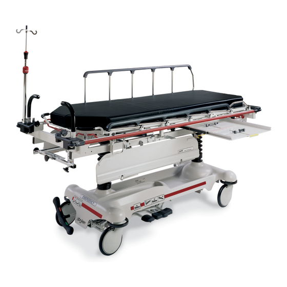
1020 full–length x–ray emergency room stretcher
Hide thumbs
Also See for Renaissance Series:
- Maintenance manual (123 pages) ,
- Operation manual (19 pages) ,
- Maintenance manual (70 pages)
Table of Contents

Related Manuals for Stryker Medical Renaissance Series


Summary of Contents for Stryker Medical Renaissance Series
- Page 1 IMPORTANT File in your maintenance records Renaissance Series 1020 Full–Length X–Ray Emergency Room Stretcher For stretchers with serial numbers of 9711034756 and above MAINTENANCE MANUAL For Parts or Technical Assistance 1–800–327–0770...
-
Page 2: Table Of Contents
Table of Contents Introduction Specifications ................Warning / Caution / Note Definition . - Page 3 Table of Contents Assembly Drawings and Parts Lists (Continued) Board Support Assembly ............. . . Push Handle Assembly .
-
Page 4: Introduction
Introduction INTRODUCTION This manual is designed to assist you with the operation and maintenance of the 1020 Full–Length X–Ray Emergency Room Stretcher. Read it thoroughly before using the equipment or beginning any maintenance on it. SPECIFICATIONS Maximum Weight Capacity 400 pounds Overall Bed Length/Width 86.5”/31.25”... -
Page 5: Preventative Maintenance
Preventative Maintenance CHECKLIST (PERFORM A MIMIMUM OF BIANNUALLY) All fasteners secure (reference all assembly prints) Siderails move and latch properly (page 7) Engage brake pedal and push on the stretcher to ensure all casters lock securely (page 17) Steer function working properly All casters secure and swivel properly Body restraints working properly I.V. -
Page 6: Cleaning
Cleaning Clean Velcro AFTER EACH USE. Saturate Velcro with disinfectant and allow disinfectant to evaporate. (Ap- propriate disinfectant for nylon Velcro should be determined by the hospital.) In general, when used in those concentrations recommended by the manufacturer, either phenolic type or quaternary type disinfectants can be used. -
Page 7: Service Information
Service Information PNEUMATIC FOWLER ADJUSTMENT Required Tools: 3/32 Hex Allen Wrench 5/8 Open End Wrench 1/8 Hex Allen Wrench Channel Lock Pliers 3/16 Hex Allen Wrench Towel or Cloth 7/16 Open End Wrench Thread ”Locktite” Adjustment Procedure: 1. Refer to drawing 1020–31–10 (Pneumatic Fowler Assembly, page 57). 2. -
Page 8: Siderail Latch Adjustment
Service Information SIDERAIL LATCH ADJUSTMENT Required Tools: 1/8 Hex Allen Wrench WARNING The siderail latch adjustment is pre–set at the factory, and should not normally need adjustment. If adjustment must be done, it is important to follow the procedure below. If it is not done properly, injury could occur. Adjustment Procedure: 1. -
Page 9: Pedal Linkage Adjustment - Dual Side Control Base
Service Information PEDAL LINKAGE ADJUSTMENT – DUAL SIDE CONTROL BASE Required Tools: 3/32 Hex Allen Wrench 7/16 Open End Wrench 1/2 Open End Wrench (2) Wooden blocks (10 – 12 inches in length) Adjustment Procedure: 1. Pump the litter up to full height. 2. -
Page 10: Pedal Linkage Adjustment - Dual End Control Base
Service Information PEDAL LINKAGE ADJUSTMENT – DUAL END CONTROL BASE Required Tools: 7/16 Open End Wrench 1/2 Open End Wrench (2) Wooden Blocks (10 – 12 inches in length) Adjustment Procedure: 1. Pump the litter up to full height. 2. Lift the base hood, separating the hood from the base frame. Using the wooden blocks, support the base hood. -
Page 11: Caster Cover Installation And Removal
Service Information CASTER COVER INSTALLATION AND REMOVAL Looking through the larger of the two side cut–outs, align cover with axle nut or bolt head, as shown. Double Prongs Push down on the opposite side of the cover until single prong engages with caster horn. Single Prong Top View (Cut–Away) Properly Attached... -
Page 12: Caster Maintenance
Service Information CASTER MAINTENANCE Required Tools: 5/8” Wrench 11/16” Wrench Maintenance Procedure: 1. Remove the plastic caster cover (see page 10). 2. Using the 5/8” wrench and the 11/16” wrench, remove the centerlock nut (item A) from the through bolt (item B) for the caster wheel. -
Page 13: Hydraulic Troubleshooting
Service Information HYDRAULIC TROUBLESHOOTING NOTE Be sure the pedal linkage has been adjusted properly before beginning service on the jacks (see page 8 or page 9). PROBLEM/SYMPTOM SOLUTION Jack will not raise to full height. Add hydraulic fluid (see p.13). Check for leaks. Jack will not hold in raised position. -
Page 14: Checking Hydraulic Fluid Level
Service Information CHECKING HYDRAULIC FLUID LEVEL Required Tools: 3/8 Open End Wrench 3/4 Open End Wrench Procedure: WARNING To avoid personal injury or damage to the stretcher, remove the litter and the base hood before beginning service on the jacks. 1. -
Page 15: Jack Descent Rate Adjustment
Service Information JACK DESCENT RATE ADJUSTMENT Required Tools: Screwdriver Bungee Cords (or equivalent) Adjustment Procedure: 1. Pump the litter up to full height. 2. Lift the base hood, separating the hood from the base frame. Using the bungee cords, support the base hood. -
Page 16: Hydraulic Check Valve Replacement
Service Information HYDRAULIC CHECK VALVE REPLACEMENT Required Tools: 3/8 Open End Wrench Stiff Wire (with bent, pointed end) Small Needle Nose Pliers 3/4 Open End Wrench Torque Wrench (with Ft. Lbs. adjust.) 7/32 Hex Allen Wrench 1/2 Inch Diameter Rod Replacement of Valve #1 WARNING To avoid personal injury or damage to the stretcher, remove the litter and the base hood before beginning... -
Page 17: Replacement Of Valve #2
Service Information HYDRAULIC CHECK VALVE REPLACEMENT (CONT’D) Replacement of Valve #2 WARNING To avoid personal injury or damage to the stretcher, remove the litter and the base hood before beginning service on the jacks. Lower the jack rod completely to relieve the pressure on the pump piston side of the jack. -
Page 18: Brake Adjustment
Service Information BRAKE ADJUSTMENT Required Tools: 3/32” Hex Allen Wrench Pry Bar Thread ”Locktite” BASE LUBRICATION Do not grease area shown. 1. Lubricate brake adjuster rod around area shown with MPG–2 grease or equivalent. -
Page 19: Assembly Drawings And Parts Lists Side Control Base Assembly
715–1–250 Side Control Base Assembly (with Brakes) - Page 20 715–1–250 Side Control Base Assembly (with Brakes) Item Part No. Part Name Qty. 715–1–245 Base Weldment Assembly 38–211 Spring 715–1–158 Caster Nut 715–1–61 Caster Brake Assembly (Page 20) Brake Adjuster Assembly 715–1–231 Brake/Steering Rod Assembly 1000–10–62 Steering Lock Linkage Bar (Page 21) Brake Cam Assembly 715–1–94...
-
Page 21: Brake Adjuster Assembly
715–1–150 Brake Adjuster Assembly Item Part No. Part Name Qty. 715–1–62 Threaded Stud Assembly 14–4 Nylon Washer 715–1–180 Bearing 28–8 Retaining Ring... -
Page 22: Brake Cam Assembly
715–1–213 Brake Cam Assembly Item Part No. Part Name Qty. 715–1–221 Brake Cam 16–59 Fiberlock Nut 8–21 Soc. Hd. Cap Screw 715–1–173 Brake Connecting Link... -
Page 23: End Control Base Assembly (With Brakes)
Assembly part number 716–1–251 Note: Parts and assemblies drawn with broken lines are part of optional accessories. - Page 24 716–1–251 End Control Base Assembly (with Brakes) Item Part No. Part Name Qty. 716–1–246 Base Weldment Ass’y 8–17 Soc. Hd. Shoulder Bolt 715–1–158 Caster Nut 715–1–61 Caster Brake Assembly (Page 20) Brake Adjuster Assembly 1210–1–345 Brake/Steer Pedal, Ft. End 1210–1–346 Brake/Steer Pedal, Hd.
-
Page 25: End Control Brake Pedal Assembly, Foot End
716–1–263 End Control Brake Pedal Ass’y, Foot End Item Part No. Part Name Qty. 716–1–275 Brake Pedal 716–1–262 Brake Rod Ass’y, Ft. End NOTE Apply plastic adhesive to the mating surfaces of item A prior to assembly. -
Page 26: End Control Brake Pedal Assembly, Head End
716–1–269 End Control Brake Pedal Ass’y, Head Item Part No. Part Name Qty. 716–1–275 Brake Pedal 716–1–267 Brake Rod Ass’y, Welded... -
Page 27: 715-2-21 Caster Assembly With Steerlock
715–2–21 Caster Assembly with Steerlock Item Part No. Part Name Qty. 700–10–50 Steer Lock Caster Weldment 715–2–25 Caster Wheel 16–60 Hex Nut 3–99 Hex Bolt 715–3–96 Hex Bolt 1000–59–10 Latch Assembly 11–310 Flat Washer... -
Page 28: Caster And Caster Cover Replacement Kits
Caster and Caster Cover Replacement Kits Item Part No. Part Name Qty. 715–2–20 Caster Assembly 715–1–266 Caster Cover, Left 715–1–265 Caster Cover, Right P/N 715–259–400 – Kit to replace 4 standard caster assemblies with necessary hardware – no caster covers. P/N 715–269–400 –... -
Page 29: Fifth Wheel Base Assembly
Optional Fifth Wheel Base Assembly Item Part No. Part Name Qty. 3–20 Hex Hd. Cap Screw 16–16 Fiberlock Nut 16–49 Nylock Hex Nut 23–25 Hex Washer Hd. Screw 26–8 Roll Pin 81–219 Bearing (page 30) Fifth Wheel Assembly 715–1–136 Fifth Wheel Spring 715–1–149 715–1–157 Fifth Wheel Bearing... - Page 30 Notes...
-
Page 31: Fifth Wheel Assembly
715–1–25 Fifth Wheel Assembly Item Part No. Part Name Qty. 715–1–339 Fifth Wheel Pivot Assembly 715–1–17 Fifth Wheel Bushing 16–11 Flexlock Nut 715–1–15 Spring 715–1–13 Fifth Wheel Bracket 16–12 Flexlock Nut 390–1–54 Wheel 3–31 Hex Head Cap Screw 3–82 Hex Head Cap Screw... -
Page 32: Reduced Length Brake/Steer Base Option
1010–90 Reduced Length Brake/Steer Base Option Item Part No. Part Name Qty. 1010–90–10 Brake Pedal Assembly 1010–90–24 Brake Bar 715–1–165 Actuator Plate Assembly 26–35 Roll Pin 26–13 Roll Pin 8–17 Shoulder Bolt 14–2 Nylon Washer 16–2 Fiberlock Nut 26–8 Roll Pin 8–21 Shoulder Bolt NOTE... -
Page 33: Side Control Base Assembly (With Jacks)
Side Control Base Assembly (with Jacks) Assembly part number 715–1–260... - Page 34 Side Control Base Assembly (with Jacks) Item Part No. Part Name Qty. 29–7 Dual Lock (Page 43) Jack Assembly 11–262 Flat Washer 3–62 Hex Hd. Cap Screw 11–3 Flat Washer 16–36 Nylock Hex Nut 715–1–192 Jack Support 3–85 Hex Hd. Cap Screw 715–1–193 Jack Support Clamp 13–38...
-
Page 35: Pedal Base Assembly, Pump
715–1–108 Pedal Base Assembly, Pump Item Part No. Part Name Qty. 715–1–83 Pedal Ass’y Weldm’t, Pump 715–1–126 Side Control Pedal Pad 81–44 Bearing, Bronze NOTE Apply plastic adhesive to the mating surfaces of item B prior to assembly. -
Page 36: Pedal Base Assembly, Head End, Left & Right
715–1–109 Pedal Base Assembly, Head End, Left Item Part No. Part Name Qty. 715–1–98 Release Ped. Wldmt., Hd. Lt. 721–40–25 Pedal 715–1–110 Pedal Base Assembly, Head End, Right Item Part No. Part Name Qty. 715–1–97 Release Pedal Weldment 721–40–25 Pedal NOTE Apply plastic adhesive to the mating surfaces of item B prior to assembly. -
Page 37: Side Control Base Assembly (With Jacks)
Side Control Base Assembly (with Jacks) - Page 38 Side Control Base Assembly (with Jacks) Item Part No. Part Name Qty. 3–47 Hex Head Cap Screw 3–62 Hex Hd. Cap Screw 3–85 Hex Hd. Cap Screw 4–146 Soc. Hd. Cap Screw 11–3 Washer 11–4 Flat Washer 11–262 Flat Washer 13–38 Ext.
-
Page 39: Side Release Pedal Assembly
Side Release Pedal Assembly Assembly part number 1210–1–150 Item Part No. Part Name Qty. 715–1–126 Side Control Pedal Pad 1210–1–152 Side Release Pedal Weldment 1... - Page 40 Notes...
- Page 41 Assembly part number 716–1–270 FOOT END HEAD END...
-
Page 42: End Control Base Assembly (With Jacks)
End Control Base Assembly (with Jacks) Item Part No. Part Name Qty. 3–4 Hex Head Cap Screw 3–62 Hex Hd. Cap Screw 3–85 Hex Hd. Cap Screw 11–3 Washer 11–13 Flat Washer 11–262 Flat Washer 13–38 Ext. Tooth Lock Washer 14–2 Washer 14–3... -
Page 43: End Control Pump Pedal Assembly, Head & Foot End
End Control Pump Pedal Assembly, Head Assembly part number 716–1–292 Item Part No. Part Name Qty. 716–1–285 Pump Pivot, Head End 26–12 Roll Pin 716–1–290 Pump Ped. Wldmt., Head 721–40–25 Pedal End Control Pump Pedal Assembly, Foot Assembly part number 716–1–288 Item Part No. -
Page 44: 715-270-400 Jack Assembly
715–270–400 Jack Assembly Assembly part number 715–270–10 (reference only) Item Part No. Part Name Qty. Item Part No. Part Name Qty. 45–904 O–Ring 388–1–38 Plug 715–1–340 Cap Assembly 715–1–322 Reservoir 390–1–243 Gasket 390–1–244 Gasket 715–1–323 Actuator Cylinder 390–1–238 Gasket, Actuator 715–1–325 Actuator (Page 44) -
Page 45: Jack Base Assembly
Jack Base Assembly Assembly part number 715–370–5 (reference only) Item Part No. Part Name Qty. Item Part No. Part Name Qty. 14–50 Bearing Retainer 715–1–327 Cylinder Wear Ring 38–311 Compression Spring 715–1–328 Piston Wear Ring 45–6 O–Ring 715–1–329 Pump Seal 45–110 O–Ring 715–1–341... -
Page 46: End Control Base Hood Labeling Assembly
End Control Base Hood Labeling Assembly Item Part No. Part Name Qty. 1001–100–1 Hood Assembly 1020–1–54 Specification Label 29–7 Dual Lock (not shown) 29–9 Dual Lock (not shown) 946–1–60 Stryker Logo Label 1010–1–50 Renaissance Series Logo Label... -
Page 47: End Control Graphics
End Control Graphics Reference below for dept. label part numbers Color Item A Control Label, Item B Control Label, Item C Stripe Label Litter Bumper Strip Head Foot 1010–800–11 1010–800–12 1010–800–13 1010–700–15 PURPLE 1010–800–21 1010–800–22 1010–800–23 1010–700–25 GREEN 1010–800–31 1010–800–32 1010–800–33 1010–700–35 GRAY... -
Page 48: Side Control Graphics
Side Control Graphics Reference previous page for dept. label part numbers. Color Item A Control Label, Right Item B Control Label, Left Litter Bumper Strip 1001–700–111 1001–700–112 1010–700–15 PURPLE 1001–700–121 1001–700–122 1010–700–25 GREEN 1001–700–131 1001–700–132 1010–700–35 GRAY 1001–700–141 1001–700–142 1010–700–45 TEAL 1001–700–151 1001–700–152... -
Page 49: Side Control Base Hood Labeling Assembly
Side Control Base Hood Labeling Assembly Item Part No. Part Name Qty. 1001–100–1 Hood Assembly 1020–1–54 Specification Label 741–1–145 Brake/Steer Label, Head 741–1–146 Brake/Steer Label, Foot 946–1–60 Stryker Logo Label 29–7 Dual Lock (not shown) 29–9 Dual Lock (not shown) 1010–1–50 Renaissance Series Logo Label... - Page 50 1020–1–10 Litter Assembly...
-
Page 51: Litter Assembly
Litter Assembly... - Page 52 Litter Assembly Item Part No. Part Name Qty. Item Part No. Part Name Qty. 1020–1–61 Litter Frame Ass’y 4–21 Soc. Hd. Cap Screw 1020–28–14 Jack Supt. Ass’y, Lt. 4–136 Hex Soc. But. Hd. Scr. 1010–54–71 Socket Ass’y, Right 8–24 Hex Soc. Sh. Bolt 1010–54–70 Socket Ass’y, Left 10–11...
-
Page 53: Trend Limiter Assembly
1000–42–49 Trend. Limiter Assembly Item Part No. Part Name Qty. 1000–42–48 Limiter Plate Ass’y 4–8 Hex Soc. Machine Screw 15–23 Hex Nut 4–142 Hex Soc. Machine Screw 715–1–114 Limiter Pin Assembly 38–233 Extension Spring 16–16 Fiberlock Nut... -
Page 54: Transfer System Assembly, Left
1020–24–10 Transfer System Assembly, Left Item Part No. Part Name Qty. 1020–32–100 Transfer Board Assembly 721–24–46 Label 1020–24–38 Connecting Link Assembly 1020–24–12 Pivot Arm Assembly, Left 1–25 Flat Hd. Machine Screw 11–224 Nylon Flat Washer 16–28 Nylock Hex Nut 4–156 Button Hd. -
Page 55: Transfer System Assembly, Right
1020–24–11 Transfer System Assembly, Right Item Part No. Part Name Qty. 1020–32–100 Transfer Board Assembly 721–24–46 Label 1020–24–37 Connecting Link Assembly 1020–24–13 Pivot Arm Ass’y Head, Rt. 1–25 Flat Hd. Machine Screw 11–224 Nylon Flat Washer 4–156 Button Hd. Cap Screw 16–28 Nylock Hex Nut 1020–24–33... -
Page 56: Assembly Drawings And Parts Lists (Continued) Board Support Assembly
1010–24–30 Arm Board Support Assembly Item Part No. Part Name Qty. 1010–24–15 Support Block 1010–24–16 Support Arm 1010–24–14 Warning Label 38–263 Spring 8–17 Shoulder Bolt 1010–26–46 Ball Knob... -
Page 57: Push Handle Assembly
Push Handle Assembly Assembly part number 1211–151–10 Item Part No. Part Name Qty. 26–10 Roll Pin 1010–254–24 Stop Link 1211–151–18 Sleeve Assembly... -
Page 58: Pneumatic Fowler Assembly
1020–31–10 Pneumatic Fowler Assembly Item Part No. Part Name Qty. Item Part No. Part Name Qty. 37–65 Hole Plug 15–37 Jam Nut 1020–31–20 Handle Assembly 21–104 Set Screw 1020–31–15 Fowler Weldment 21–119 Set Screw 1020–31–39 Fowler Skin 1010–32–66 Hole Plug 1510–31–28 Yoke 4–149... -
Page 59: Pneumatic Fowler To Frame Assembly
1020–31–11 Pneumatic Fowler to Frame Assembly Item Part No. Part Name Qty. 1010–31–78 Gas Cylinder 1020–31–25 Cylinder Mount 16–35 Nylock Hex Nut 14–29 Flat Washer 3–78 Hex Hd. Cap Screw 16–28 Nylock Hex Nut 1020–31–38 Fowler Rest Bumper 1020–31–17 Fowler Rest, Right 1020–31–19 Fowler Rest, Left... -
Page 60: Manual Fowler Assembly
1020–32–58 Manual Fowler Assembly Item Part No. Part Name Qty. 37–65 Hole Plug 1020–32–57 Fowler Weldment 1020–31–39 Fowler Skin 25–99 Pop Rivet 1010–32–66 Hole Plug 4–149 But. Hd. Cap Screw 16–3 Self–Locking Nut 25–69 Pop Rivet 1020–23–12 Tray Hinge, Left 1020–23–13 Tray Hinge, Right 1020–23–14... -
Page 61: Manual Fowler To Frame Assembly
1020–32–59 Manual Fowler to Frame Assembly Hex Hd. Cap Screw p/n 3–78 (ref.) Nylock Nut p/n 16–29 (ref.) Litter Assembly p/n 1020–1–10 (ref.) HEAD END Hex Hd. Cap Screw p/n 3–78 (ref.) Item Part No. Part Name Qty. 1020–32–54 Pivot Leg Assembly 3–78 Hex Hd. -
Page 62: Foot Section Assembly
1020–32–55 Foot Section Assembly Item Part No. Part Name Qty. 1020–32–25 Footsection Weldment 1020–32–26 Footsection Skin 25–99 Pop Rivet 7900–1–102 Velcro 24.5”... -
Page 63: Foot End Push Handle Assembly
1020–51–10 Foot End Push Handle Assembly Item Part No. Part Name Qty. 1010–51–19 Guard 1000–58–19 Push Handle 1020–51–15 Handle Socket 1020–51–17 Handle Socket 1010–51–18 Rubber Bumper 25–79 Pop Rivet 26–10 Roll Pin 16–28 Nylock Nut 26–11 Roll Pin 3–78 Hex Hd. Bolt 1010–254–24 Stop Link... -
Page 64: Siderail Assembly, Right & Left
1010–26–17 & 1010–26–19 Siderail Ass’y, Right & Left (LEFT SIDERAIL IS SHOWN) Item Part No. Part Name Qty. 1010–26–15 Top Rail 1010–26–83 Upright 1010–26–84 Upright, Bent 1010–26–82 Sleeve Bearing 25–106 Semi–Tubular Rivet 1010–26–10 Round Hole Plug 1010–26–85 Upright, Latch 1010–26–12 Bent Spindle Rest... -
Page 65: X-Ray Tray Assembly, Right Side Loading
1020–22–10 X–Ray Tray Assembly, Right Side Loading... - Page 66 1020–22–10 X–Ray Tray Assembly, Right Side Loading Item Part No. Part Name Qty. Item Part No. Part Name Qty. 1020–22–44 Tray Frame Ass’y 1020–22–41 Spur Gear 1020–22–11 Outer Slide, Mach’d 52–250 Spacer 1020–22–15 Pivot Tube Ass’y 1010–32–66 Hole Plug 1020–22–7 Brake Handle 1020–22–43 Rack, Modified...
-
Page 67: X-Ray Tray Assembly, Left Side Loading
1020–21–10 X–Ray Tray Assembly, Left Side Loading... - Page 68 1020–21–10 X–Ray Tray Assembly, Left Side Loading Item Part No. Part Name Qty. Item Part No. Part Name Qty. 1020–21–44 Tray Frame Ass’y 1020–22–13 Inner Slide, Mach’d 1020–22–11 Outer Slide, Mach’d 1020–22–12 Support, Mach’d 1020–21–15 Pivot Tube Ass’y 1020–22–45 Stop, First Stage 1020–21–7 Brake Handle 1–87...
-
Page 69: Grid Holder Assembly
1020–27–10 Grid Holder Assembly Item Part No. Part Name Qty. 1020–27–21 Guide Weldment, Rt. 1020–27–22 Guide Weldment, Lt. 1020–27–11 Slider Weldment 11–271 Fender Washer 4–131 Button Hd. Cap Screw 1020–27–24 ”L” Bracket... -
Page 70: Centering Device Option Assembly
1020–20 Centering Device Option Assembly BOTTOM VIEW Item Part No. Part Name Qty. 1–22 Flat Hd. Mach. Screw 1–85 Flat Hd. Mach. Screw 4–127 Soc. Hd. Cap Screw 4–169 But. Hd. Cap Screw 4–170 But. Hd. Cap Screw 11–11 Fiber Washer 11–132 Nylon Washer 24–51... -
Page 71: Fowler X-Ray Cassette Assembly
1020–23 Fowler X–Ray Cassette Assembly Item Part No. Part Name Qty. 1020–23–11 Tray 1020–23–16 Post Housing 1020–23–25 Actuating Rod 926–23–64 Post 1010–23–37 Rod Guide 1020–23–21 Knob 1010–23–28 Tray Angle 926–23–70 Block Assembly 926–23–69 Washer 14–3 Washer 38–122 Compression Spring 1020–23–26 Spacer 1020–23–19 Tray Hinge, Right... -
Page 72: Heel Stirrup And Support Assembly
1020–55–10 Heel Stirrup and Support Assembly Item Part No. Part Name Qty. (Page 72) Rt. Stirrup Support Ass’y (Page 73) Lt. Stirrup Support Ass’y (Page 74) Stirrup Assembly 3–78 Hex Head Cap Screw 1020–55–15 Backer Assembly 16–28 Nylock Hex Nut 11–158 Flat Washer... -
Page 73: Right Stirrup Support Assembly
1010–55–15 Right Stirrup Support Assembly Item Part No. Part Name Qty. 1010–55–16 Right Support Tube Ass’y 1010–55–20 Mounting Bracket 650–2–32 Lock Screw Assembly 966–51–19 Wedge Lock, Modified 38–171 Compression Spring 26–7 Roll Pin 14–40 Nylon Flat Washer 24–11 Knob... -
Page 74: Left Stirrup Support Assembly
1001–55–16 Left Stirrup Support Assembly Item Part No. Part Name Qty. 1010–55–26 Left Support Tube Ass’y 1010–55–20 Mounting Bracket 650–2–32 Lock Screw Assembly 966–51–19 Wedge Lock, Modified 38–171 Compression Spring 26–7 Roll Pin 14–40 Nylon Flat Washer 24–11 Knob... -
Page 75: Heel Stirrup Assembly
1010–55–29 Heel Stirrup Assembly Item Part No. Part Name Qty. 390–20–13 Stirrup 390–20–9 Stirrup Holder Assembly 1010–55–30 Extension Tube Assembly 24–11 Knob 26–43 Roll Pin 22–8 Drive Screw... -
Page 76: 2-Stage I.v. Pole Assembly
1211–110–10 2–Stage I.V. Pole Assembly Item Part No. Part Name Qty. 1001–59–32 Base Tube Assembly 1001–59–31 Extension Tube Assembly 1210–110–47 Lock Ring 1210–110–49 Lock Actuator 14–20 Nylon Flat Washer As Req’d 1010–59–16 I.V. Hook 52–17 Nylon Spacer 926–400–62 Stop Sleeve 1210–110–46 Back–Up Ring 8–31... -
Page 77: 2-Stage I.v. Mounting Assembly
1010–80 & 1010–81 2–Stage I.V. Mounting Assembly 1010–80 (Foot) 1010–81 (Head) Item Part No. Part Name Qty. Item Part No. Part Name Qty. (Page 75) I.V. Pole Ass’y (Page 75) I.V. Pole Ass’y 1001–259–11 I V. Socket Ass’y 1001–259–11 I V. Socket Ass’y 4–91 But. -
Page 78: Replacement 2-Stage I.v. Pole, Foot End
1010–80–100 Replacement Perm. I.V. Pole Ass’y, Foot Item Part No. Part Name Qty. (Page 75) I.V. Pole Ass’y 1001–259–11 Socket Ass’y 4–91 But. Hd. Cap Screw 16–28 Nylock Hex Nut 4–161 Button Hd. Cap Screw 16–20 Self–Locking Nut 1001–59–42 I.V. Plug... -
Page 79: Replacement 2-Stage I.v. Pole, Head End
1010–81–100 Replacement Perm. I.V. Pole Ass’y, Head Item Part No. Part Name Qty. 16–20 Self–Locking Nut (Page 75) I.V. Pole Ass’y 1001–259–11 Socket Ass’y 4–91 But. Hd. Cap Screw 16–28 Nylock Hex Nut 3–50 Hex Hd. Cap Screw 4–163 Button Hd. Cap Screw 1001–59–42 I.V. -
Page 80: 3-Stage I.v. Pole Mounting Assembly
1020–61 & 1020–62 3–Stage I.V. Pole Mounting Ass’y Item Part No. Part Name Qty. (page 80) I.V. Pole Assembly 1001–259–11 I.V. Socket Assembly 4–91 But. Hd. Cap Screw 16–20 Self–Locking Nut... -
Page 81: 3-Stage I.v. Pole Assembly
1020–61–10 3–Stage I.V. Pole Assembly Item Part No. Part Name Qty. 1010–61–24 Base Tube Assembly (page 81) 2nd Stage Assembly (page 82) 3rd Stage Assembly 26–6 Roll Pin 7–4 Truss Hd. Mach. Screw 52–17 Nylon Spacer 1010–59–16 I.V. Hook 14–20 Nylon Flat Washer 1010–61–14 Collar... -
Page 82: 2Nd Stage Assembly
1010–61–25 2nd Stage Assembly Item Part No. Part Name Qty. 1010–61–30 2nd Tube Assembly 1210–110–46 Back–Up Ring 1210–110–47 Lock Ring 1210–110–49 Lock Actuator... -
Page 83: 3Rd Stage Assembly
1020–61–20 3rd Stage Assembly Item Part No. Part Name Qty. 38–303 Spring 1010–61–13 Ball Retainer 1010–61–15 Stop Nut 1010–61–16 Retaining Shaft 1010–61–17 Thumb Knob 1010–61–18 Hand Guard 1020–61–19 3rd Extension Rod 31–21 Ball... -
Page 84: Tethered I.v. Assembly
1010–22–26 Tethered I.V. Pole Assembly Item Part No. Part Name Qty. 721–47–6 I.V. Holder 721–47–14 Retainer 1010–22–27 Cable Assembly 21–16 Set Screw 1010–22–27 Label... -
Page 85: Tethered I.v. Pole Assembly
1010–22–10 Tethered I.V. Mounting Assembly Item Part No. Part Name Qty. 1010–22–25 Trough Assembly (Page 83) Tethered I.V. Assembly 25–92 Pop Rivet 34–22 Loop Clamp... -
Page 86: Upright Oxygen Bottle Holder
1020–30 Upright Oxygen Bottle Holder Item Part No. Part Name Qty. 1020–30–11 Upright Bottle Holder 27–12 Cotter Pin 1020–30–17 Specification Label 741–34* Foot Board/Chartholder Item Part No. Part Name Qty. 946–28–11 Chart Holder 741–29–18 Head/Foot Board 42–6 Collar * Replacement Part Number 741–34–100... -
Page 87: C-Spine Cassette Holder Assembly
1020–70–1 C–Spine Cassette Holder Assembly Item Part No. Part Name Qty. 1010–70–25 I.V. Adaptor 1020–70–18 Specification Label 11–3 Flat Washer 4–91 Soc. Hd. Cap Screw (page 87) Support Pole Ass’y (page 88) Storage Bracket Ass’y 37–56 Washer 3–47 Hex Hd. Cap Screw 37–55 16–28 Nylock Nut... -
Page 88: C-Spine Support Pole Assembly
1010–70–10 C–Spine Support Pole Assembly View A–A Item Part No. Part Name Qty. 1010–70–33 Support Tube Cap 26–6 Roll Pin 1010–70–34 Support Arm Weldment 1010–70–42 Cassette Holder Weldment 1010–70–50 Adjustment Tube Weldment 1010–70–30 Base Tube Weldment 1010–70–45 Knob 25–55 Pop Rivet 1010–70–44 Pivot Pin 26–5... -
Page 89: C-Spine Storage Bracket Assembly
1020–70–19 C–Spine Storage Bracket Assembly 5.5” (Ref.) 4.5” (Ref.) Item Part No. Part Name Qty. 1020–70–20 Storage Bracket Weldment 1010–70–45 Knob 1010–70–23 Storage Label... -
Page 90: Replacement Parts
Replacement Parts and Kits PART NAME PART NUMBER Caster Cover Kit ..........1010–56–100 C–Spine Cassette Holder . -
Page 91: Warranty
Warranty Limited Warranty: Stryker Medical Division, a division of Stryker Corporation, warrants to the original purchaser that its products should be free from defects in material and workmanship for a period of one (1) year after date of delivery. Stryker’s obligation under this warranty is expressly limited to supplying replacement parts and labor for, or replacing, at its option, any product which is, in the sole discretion of Stryker, found to be defective. -
Page 92: Return Authorization
Warranty Return Authorization: Merchandise cannot be returned without approval from the Stryker Customer Service Department. An autho- rization number will be provided which must be printed on the returned merchandise. Stryker reserves the right to charge shipping and restocking fees on returned items. SPECIAL, MODIFIED, OR DISCONTINUED ITEMS NOT SUBJECT TO RETURN. - Page 93 6300 Sprinkle Road, Kalamazoo, MI 49001–9799 (800) 327–0770 DH 11/97 1020–32–34 REV K...
Need help?
Do you have a question about the Renaissance Series and is the answer not in the manual?
Questions and answers