Advantech PPC-6151C User Manual
15"/17" configurable panel pc chassis with selectable mini-itx motherboard
Hide thumbs
Also See for PPC-6151C:
- User manual (66 pages) ,
- Startup manual (9 pages) ,
- User manual (64 pages)

Related Manuals for Advantech PPC-6151C


Summary of Contents for Advantech PPC-6151C
- Page 1 User Manual PPC-6151C/6171C 15"/17" Configurable Panel PC Chassis with Selectable Mini-ITX Motherboard...
- Page 2 The documentation and software included with this product are copyrighted 2017 by Advantech Co., Ltd. All rights are reserved. Advantech Co., Ltd. reserves the right to improve the products described in this manual at any time without notice. No part of this manual may be reproduced, copied, translated, or transmitted in any form or by any means without the prior written permission of Advantech Co., Ltd.
- Page 3 This product has passed the CE test for environmental specifications when shielded cables are used for external wiring. We recommend the use of shielded cables. This type of cable is available from Advantech. Please contact your local supplier for ordering information.
- Page 4 The sound pressure level at the operator's position does not exceed 70 dB (A) in accordance with IEC 704-1:1982 specifications. DISCLAIMER: These instructions are provided according to IEC 704-1. Advantech disclaims all responsibility for the accuracy of any statements contained herein.
- Page 5 The power is suitable for areas with an altitude of 5000 M and below. Battery Information Batteries, battery packs, and accumulators should not be disposed of in unsorted household waste. Please use the public collection system to return, recycle, or treat them in compliance with your local regulations. PPC-6151C/6171C User Manual...
- Page 6 Upon opening the carton, check that the items below have been included in your shipment. Model Item Image Chassis Riser card PCIe x4 Riser card PCI PPC-6151C/6171C- RTAE User manual Warranty card HDD screws M/B and riser card screws 6 Panel bracket and screws 10 Mini PCIe screw PPC-6151C/6171C User Manual...
- Page 7 DP input cable USB input cable PPC-6151C/6171C- SATA cable RMAE SATA power cable User manual Warranty card HDD screws M/B and riser card screw Panel bracket and screws 10 DC bracket DC bracket screws Mini PCIe screw PPC-6151C/6171C User Manual...
- Page 8 Addi- tionally, please notify the carrier. Retain the shipping carton and packing material for inspection by the carrier. After inspection, we will make arrangements to repair or replace the unit. PPC-6151C/6171C User Manual viii...
-
Page 9: Table Of Contents
Specification Comparison ............. 4 1.4.2 General Specifications ..............4 External View .................... 5 System View ..................... 7 Dimensions ....................8 Figure 1.1 PPC-6151C dimensions ..........8 Figure 1.2 PPC-6171C dimensions ..........9 Chapter System Installation and Setup ..11 Anti-Static Precautions................12 Installation Procedures................ - Page 10 EAMB-BE02 2 x PCIe x 1 Riser Card......... 47 A.1.4 EAMB-BE03 1 x PCIe x 1+1 x PCI Riser Card ......48 Appendix B BSMI ROHS........49 BSMI ROHS.................... 50 BSMI 警語及注意事項........... 50 Appendix C China ROHS........51 China ROHS ................... 52 PPC-6151C/6171C User Manual...
-
Page 11: Chapter 1 Introduction
Chapter Introduction Overview Features Chassis Comparison Specifications External View System View Dimensions... -
Page 12: Overview
Mini-iTX motherboards to satisfy customer requirements regarding price and functionality. PPC-6151C/6171C features a true flat bezel to meet market demands for stylish design, as well as an additional reservation port and expansion slot to accommodate various applications. The PPC-6151C/6171C series devices were developed follow- ing two design concepts - one is an optimized design, which can be equipped with a motherboard designed by Advantech’s PPC team;... -
Page 13: Chassis Comparison
Note! Users can determine which chassis they are using by observing whether the system features a USB port and a DP port. After identifying the chassis type, refer to Chapters 2.3 and 2.4 (PPC-6151C/6171C- RTAE&PPC-6151C/6171C-RMAE) for installation. Note! When selecting a motherboard, please refer to the PPC-6151C/6171C's selection guide. -
Page 14: Specifications
Based on motherboard specifications Power Consumption Input Voltage 100 ~ 240 V , 250W Backlight LCD Display 50,000 hours minimum Lifetime Touch Type Analog resistive 5-wire/projected capacitive (optional) Light 80+/-5% Transmission Touchscreen Controller USB interface Durability 35 million (Touches) PPC-6151C/6171C User Manual... -
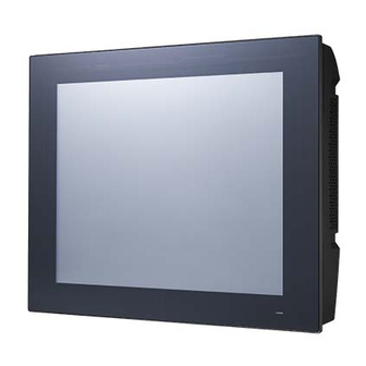
Page 15: External View
*1 x USB 2.0 (for connecting the motherboard and touch controller) External View The front of PPC-6151C/6171C is a flat panel LCD screen enclosed in an AL frame. (When placed upright on a desk, the PPC-6151C/6171C front panel appears as shown below.) - Page 16 1. Air outlets 2. Antenna holes 3. Quick installation clip (1) 4. Panel mount bracket holes (10 on PPC-6151C/6171C) 5. Air inlets PPC-6151C/6171C User Manual...
-
Page 17: System View
System View PPC-6151C/6171C-RTAE barebone chassis PPC-6151C/6171C-RMAE barebone chassis With PPC-MB-8260AE motherboard With AIMB-275G motherboard PPC-6151C/6171C User Manual... -
Page 18: Dimensions
Dimensions PPC-6151C: 379.36 103.60 7.50 391.40 Cut out Figure 1.1 PPC-6151C dimensions PPC-6151C/6171C User Manual... - Page 19 Max. depth for VESA mounting screw is M4*8L(mm). Optional kit for VESA mounting. Figure 1.2 PPC-6171C dimensions Fixed VESA screw specification: M4; screw depth: 8 mm (Max) Warning! Use suitable mounting apparatus to avoid risk of injury. PPC-6151C/6171C User Manual...
- Page 20 PPC-6151C/6171C User Manual...
-
Page 21: Chapter 2 System Installation And Setup
Chapter System Installation and Setup Anti-Static Precautions Installation Procedures PPC-6151C/6171C-RTAE Moth- erboard Installation PPC-6151C/6171C-RMAE Moth- erboard Installation Component Setup Mount Installation Quick Installation... -
Page 22: Anti-Static Precautions
Always wear an anti-static wristband when handling the PPC model; this can prevent ESD from damaging the board or causing personal injury. Note! Reference Chapter 1.3 (Chassis Comparison) to determine the chassis type, then refer to Chapters 2.3 and 2.4 (for PPC-6151C/6171C-RTAE and PPC-6151C/6171C-RMAE, respectively) for the installation guide- lines. Installation Procedures The procedures listed below must be followed to ensure correct installation. -
Page 23: Ppc-6151C/6171C-Rtae Motherboard Installation
PPC-6151C/6171C-RTAE Motherboard Installation 2.3.1 Remove the Back Cover Unscrew the six screws and remove the rear cover. 2.3.2 Remove the Reinforced Board Remove the two screws of the reinforced board. PPC-6151C/6171C User Manual... -
Page 24: Check And Adjust Jumpers On The Motherboard
2.3.3 Check and Adjust Jumpers on the Motherboard Jumper settings PPC-MB-8260AE motherboard with PPC-6151C-RTAE Resolution 1024*768 (24 bit) LED panel PWR +3.3V Backlight level +3.3V Brightness PWM level +3.3V PPC-6151C/6171C User Manual... - Page 25 PPC-MB-8260AE motherboard with PPC-6171C-RTAE Resolution 1024*768 (24 bit) LED panel PWR Backlight level +3.3V Brightness PWM level Note! For more information regarding the jumpers and connectors, please refer to the PPC-MB-8260AE startup manual (P/N:2003826000). PPC-6151C/6171C User Manual...
-
Page 26: Install The Ppc-Mb-8260Ae Motherboard
Using four screws provided in the accessory box, affix the motherboard onto the motherboard frame. (Motherboards must be purchased separately.) Note! Please refer to the datasheet when selecting the motherboard type in order to ensure optimum performance, maximum security, and sufficient air circulation. PPC-6151C/6171C User Manual... -
Page 27: Connect The Motherboard Wires
2.3.5 Connect the Motherboard Wires PPC-6151C/6171C-RTAE and PPC-MB-8260AE assembly 2. Backlight 1. LVDS 3. SYS FAN1 4. SYS FAN2 5. HDD conn. 6. Touch 7. DIO 8. COM3 9. COM4 15. LED conn. 10. COM5 14. SPEAKER 11. Power switch 12. -
Page 28: Ppc-6151C/6171C-Rmae Motherboard Installation
PPC-6151C/6171C-RMAE Motherboard Installation 2.4.1 Remove the Back Cover Unscrew the six screws and remove the rear cover. 2.4.2 Remove the Reinforced Bracket Remove the two screws of the reinforced bracket. PPC-6151C/6171C User Manual... -
Page 29: Check Jumper Setting Of The Chassis
2.4.3 Check Jumper Setting of the Chassis AIMB-275 motherboard with PPC-6151C-RMAE Resolution 1024*768 (24 bit) LED panel PWR +3.3V JP2(4-6) Backlight level +3.3V JP2(3-5) Brightness PWM level +3.3V PPC-6151C/6171C User Manual... - Page 30 AIMB-275 motherboard with PPC-6171C-RMAE Resolution 1024*768 (24 bit) LED panel PWR JP2(4-6) Backlight level +3.3V JP2(1-3) Brightness PWM level PPC-6151C/6171C User Manual...
-
Page 31: Install The Mini-Itx Motherboard (Aimb-275)
2.4.4 Install the Mini-ITX Motherboard (AIMB-275) Retrieve the I/O bracket from the AIMB-275 accessory box. Remove the I/O port blades. Take off I/O port blade Install the motherboard I/O bracket into chassis. PPC-6151C/6171C User Manual... -
Page 32: Connect The Motherboard Wires
Use four screws from the accessory box to affix the motherboard in place. 2.4.5 Connect the Motherboard Wires PPC-6151C/6171C-RMAE and AIMB-275 assembly 1. SATA conn. 2. CPU fan 3. SYS fan 1 10. Daughter board Power 4. PS_ON conn. 11.Touch conn. - Page 33 Speaker cable main board daughter board Note! Please refer to the PPC-6151C/6171C selection guide when selecting the motherboard type in order to ensure optimum performance, maxi- mum security, and sufficient air circulation. The cable connection is based on the motherboard specifications.
- Page 34 Retrieve DC bracket screws from the accessory box and affix the DC bracket in place. Note! For the PPC-6151C/6171C model, users are advised not use the DC port on the motherboard. PPC-6151C/6171C User Manual...
-
Page 35: Connect The Daughter Board And Motherboard Using A Cable
Connect the motherboard. Note! Use a DP cable to connect the motherboard DP port and the chassis DP Input port. Use USB cable to connect one of the motherboard USB ports. The motherboards must have a DP port. PPC-6151C/6171C User Manual... -
Page 36: Component Setup
Exercise caution when handling the motherboard CPU pins. Reference the datasheet when selecting the motherboard CPU. Note! After installing the CPU installation, ensure the CPU surface is covered in thermal grease. (Thermal grease is included in the PPC-MB-8260AE motherboard accessory box.) PPC-6151C/6171C User Manual... -
Page 37: Cpu Cooler Installation
1. PPC-MB-8260AE motherboard 1). Insert the memory card into the slot at a 45 degree angle. The gold fingers on the edge of the card must be completely inserted into the slot to ensure a good con- nection. 45° PPC-6151C/6171C User Manual... - Page 38 2. AIMB-275 motherboard 1). Insert the memory card into the slot at a 45 degree angle. The gold fingers on the edge of the card must be completely inserted into the slot to ensure a good con- nection. 45° PPC-6151C/6171C User Manual...
-
Page 39: Hdd Installation
Unscrew the four screws indicated in the image below. Then remove the HDD bracket. Place the HDD into the HDD bracket and affix it into place using four screws. (HDD screws are included in the accessory box.) PPC-6151C/6171C User Manual... -
Page 40: Wi-Fi Module Installation
In the procedures listed below for installing a wireless LAN card, a PPC-WLAN-A1E motherboard is used in the example figures. Attach the wireless LAN card to the ironware bracket using the screws provided with the Wi-Fi module. PPC-6151C/6171C User Manual... - Page 41 Insert the wireless card into the appropriate mainboard slot. Then affix the card in place using a screw included in the accessory box. Connect the cables of the wireless LAN card to the antenna holder. Note the installation direction of the cable end and nut/washer. PPC-6151C/6171C User Manual...
- Page 42 Lock the assembled antenna holder onto the machine. Then connect the cable to wireless LAN card. PPC-6151C/6171C User Manual...
-
Page 43: Expansion Card Installation
2.5.6 Expansion Card Installation Insert the PCI riser card (included in the PPC-6151C/6171C accessory box) into the slot and affix it in place using two screws. One PCIe x4 and two PCI riser cards are provided in the PPC-6151C/6171C accessory box, allowing users to customize their system according to their requirements. -
Page 44: Rear Cover Installation
Rear Cover Installation Please refer to above figures for rear cover installation. Align left and right bottom corners of rear cover and front panel (refer to red circles shown), and along with the red arrow direction for installation. PPC-6151C/6171C User Manual... -
Page 45: Mount Installation
Put machine into the cabinet and prepare the wall mount brackets. Panel mount bracket Lock screws and fixed machine. Panel mount bracket Put the plastic plugs into hole according to the arrow and hookup machine. Screw Lock screw and fixed machine. PPC-6151C/6171C User Manual... -
Page 46: Quick Installation
Users can independently complete the panel wallmount installation by following the quick installation procedures listed below. Loosen the two screws at the base (see the figure below). Push the machine into a gap in the wall. The spring hook will lock the machine into the wall. PPC-6151C/6171C User Manual... - Page 47 Note! The recommended mount thickness is no more than 2 mm (0.079”) according to quick installation guide. For other situations, the recom- mended thickness is 6 mm or less (0.236”). PPC-6151C/6171C User Manual...
- Page 48 PPC-6151C/6171C User Manual...
-
Page 49: Chapter 3 System Maintenance
Chapter System Maintenance... -
Page 50: Introduction
Please read the warning at the beginning of the previous chapter before attempting to access any of the PPC internal components. Follow the steps in Sections 2.3.1 and 2.3.2. Remove the four screws from the power bracket. Disconnect the power from the motherboard frame. PPC-6151C/6171C User Manual... -
Page 51: Daughter Board Replacement
Remove the rear cover to access the daughter board. Next, disconnect the power cable, speaker cable, touch cable, backlight cable, LVDS cable, LED cable, and audio cable, and also remove the two screws, as shown below. Power Speaker Touch Backlight control Screw Backlight Audio Adjust LVDS Screw PPC-6151C/6171C User Manual... -
Page 52: System Fan Replacement
Remove the old daughter board and replace it with the new daughter board. System Fan Replacement Remove the eight screws from the reinforced bracket. PPC-6151C/6171C User Manual... -
Page 53: Lcd And Touch Panel Replacement
The touch panel is attached to the front of the display using an adhesive. All surfaces must be thoroughly cleaned before adhesion to ensure durable bonding. Therefore, users are not advise to replace the touch panel themselves. Should you require a replacement, contact Advantech’s Customer Service center. PPC-6151C/6171C User Manual... - Page 54 PPC-6151C/6171C User Manual...
-
Page 55: Appendix Apci/Pcie Riser Card
Appendix PCI/PCIE Riser Card... -
Page 56: Riser Card Introduction
Riser Card Introduction A.1.1 PPCB-003 PCI Riser Card The total current load provided by the PPC-6151C/6171C PCI slot does not exceed 20 W. Additional details are provided below. -12V 0.1A +12V 0.5A +3.3V 2.5A +3.3VSB 0.25A A.1.2 PPCB-006 PCIE x4 Riser Card The total current load provided by the PPC-6151C/6171C PCI slot does not exceed 25 W. -
Page 57: Eamb-Be02 2 X Pcie X 1 Riser Card
A.1.3 EAMB-BE02 2 x PCIe x 1 Riser Card The total current load provided by the PPC-6151C/6171C PCIe slot does not exceed 25 W.Additional details are provided below. ________________________________________ +12V 2.1A ________________________________________ +3.3V 3A ________________________________________ +3.3VSB 0.375A ________________________________________ PPC-6151C/6171C User Manual... -
Page 58: Eamb-Be03 1 X Pcie X 1+1 X Pci Riser Card
A.1.4 EAMB-BE03 1 x PCIe x 1+1 x PCI Riser Card The total current load provided by the PPC-6151C/6171C PCIe and PCI slot does not exceed 25 W. Additional details are provided below. ________________________________________ -12V 0.1A ________________________________________ +12V 1.0A ________________________________________... -
Page 59: Bsmi Rohs
Appendix BSMI ROHS... -
Page 60: Bsmi Rohs
備考 3.“ - ” 係指該項限用物質為排除項目。 Note 3. “-” indicates that the restricted substance is not present in the product. BSMI 警語及注意事項 警語:使用過度恐傷害視力。 注意事項: 1) 使用 30 分鐘請休息 10 分鐘。 2)未滿 2 歲幼兒不看熒幕,2 歲以上每天看熒幕不要超過 1 小時。 PPC-6151C/6171C User Manual... - Page 61 Appendix China ROHS...
-
Page 62: China Rohs
China ROHS Dear Customer, Thank you for choosing this Advantech product. However, to comply with China’s electronic industry standard SJ/T11364, which necessitates listing for restricted use the hazardous substances in electrical and electronic products, this chapter describes the product’s environmental impact/protection. - Page 63 PPC-6151C/6171C User Manual...
- Page 64 No part of this publication may be reproduced in any form or by any means, such as electronically, by photocopying, recording, or otherwise, without prior written permission from the publisher. All brand and product names are trademarks or registered trademarks of their respective companies. © Advantech Co., Ltd. 2017...
Need help?
Do you have a question about the PPC-6151C and is the answer not in the manual?
Questions and answers