
Related Manuals for Advantech PPC-L127T


Summary of Contents for Advantech PPC-L127T
- Page 1 PPC-L127T ® ® Intel Celeron M Processor- based Fanless Panel PC with 12.1" TFT-LCD User Manual...
- Page 2 Microsoft Windows is a registered trademark of Microsoft Corp. RTL is a trademark of Realtek Semiconductor Co., Ltd. All other product names or trademarks are properties of their respective owners. For more information on this and other Advantech products, please visit our websites at: http://www.advantech.com http://www.advantech.com/ppc For technical support and service, please visit our support website at: http://support.advantech.com...
- Page 3 FCC Class B This equipment has been tested and found to comply with the limits for a Class B digital device, pursuant to Part 15 of the FCC Rules. These limits are designed to provide reasonable protection against harmful interfer- ence when the equipment is operated in a residential environment.
-
Page 4: Packing List
If any of these items are missing or damaged, contact your distributor or sales representative immediately. Additional Information and Assistance Step 1. Visit the Advantech web site at www.advantech.com where you can find the latest information about the product. Step 2. Contact your distributor, sales representative, or Advantech's cus- tomer service center for technical support if you need additional assistance. -
Page 5: Contact Information
5. CompactFlash: Turn off power before insert- ing or removing CompactFlash storage card. Contact information: Our European representative: Advantech Europe GmbH Kolberger Straße 7 D-40599 Düsseldorf, Germany Tel: 49-211-97477350 Fax: 49-211-97477300... -
Page 6: Safety Instructions
The sound pressure level at the operator's position according to IEC 704-1:1982 is no more than 70 dB (A). DISCLAIMER: This set of instructions is given according to IEC 704-1. Advan- tech disclaims all responsibility for the accuracy of any statements contained herein. PPC-L127T User Manual... - Page 7 Typ. Entsorgung gebrauchter Batterien navh Angaben des Herstellers. Der arbeitsplatzbezogene Schalldruckpegel nach DIN 45 635 Teil 1000 beträgt 70dB(A) oder weiger. DISCLAIMER: This set of instructions is given according to IEC704-1. Advantech disclaims all responsibility for the accuracy of any statements contained herein.
-
Page 9: Table Of Contents
Chapter 2 System Setup...........10 A Quick Tour of the Panel PC ........10 Figure 2.1:Front view of PPC-L127T panel PC ... 10 Figure 2.2:Rear view of Panel PC ........ 11 Figure 2.3:Side view of the panel PC ......11 Figure 2.4:Bottom view of the panel PC ...... 12 Installation Procedures ............ - Page 10 4.1.3 Locating jumpers and connectors ......... 24 Figure 4.1:Jumpers and Connectors on the PPC-L127T motherboard24 CMOS Clear for External RTC (JP1) ......25 Table 4.2:CMOS clear (J1)........... 25 4.2.1 COM1/COM2/COM3/COM4 pin 9 output setting (JP2; JP3)26 Table 4.3:COM1/ COM2/COM3/COM4 pin 9 output set- ting (JP2;...
-
Page 11: General Information
General Information This chapter gives background information on the PPC-L127T panel Sections include: • Introduction • General Specifications • LCD Specifications • Dimensions... -
Page 12: Chapter 1 General Information
Chapter 1 General Information 1.1 Introduction The PPC-L127T panel PC is an Intel low-power Celeron M processor computer that is designed to serve as a human machine interface (HMI) and as a multimedia computer. It is a PC-based system with 12.1" color TFT LCD display, on-board PCI Ethernet controller, multi-COM port interfaces and an audio controller. -
Page 13: General Specifications
1.2 General Specifications General • Dimensions (W x H x D): 340.5 x 269.3 x 70.5 mm • Weight: 3.25 kg • Power supply: ATX type Input Voltage: +12 ~ 25 VDC, 4.5A Max. Power adaptor: AC/DC (Optional PS-DC19-L60) Input voltage: 100 ~ 240 V Output voltage: 19 V @ 3.16 A •... - Page 14 • Chipset: Realtek RTL 8100CL PCI local bus Ethernet controller • Ethernet interface: Full compliance with IEEE 802.3u 100Base-T and 10 Base-T specifications. Includes software drivers and boot ROM • 100/10Base-T auto-sensing capability • Wake-on-LAN: Supports Wake-on-LAN function with ATX power control PPC-L127T User Manual...
- Page 15 Touchscreen (Optional) Type Analog Resistive Resolution Continuous Light Transmission Controller USB interface Power Consumption <5 V@ 60 mA Software Driver Supports Windows NT/98/ 2000/ME/XP Durability 35 million (touches in a lifetime) Note: The panel PC with the optionally installed touchscreen will share the COM4 port. Once the touchscreen is installed, COM4 cannot be used for other purposes.
-
Page 16: Lcd Specifications
The color LCD display installed in the panel PC is high-quality and reliable. However, it may contain a few defective pixels which do not always illuminate. With current technology, it is impossible to completely eliminate defective pixels. Advantech is actively working to improve this technology. PPC-L127T User Manual... -
Page 17: Dimensions
1.4 Dimensions Figure 1.1: Dimensions of PPC-L127T Chapter 1... -
Page 19: System Setup
System Setup This chapter details system setup on the PPC-L127T panel PC. Sections include: • A Quick Tour of the Panel PC • Installation procedures • Running the BIOS Setup Program • Installing System Software • Installing the Drivers... -
Page 20: Chapter 2 System Setup
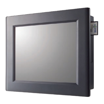
When you place the panel PC upright on the desktop, its front panel appears as shown in Figure 2-1. Figure 2.1: Front view of PPC-L127T panel PC When you turn the panel PC around and look at its rear cover, you will find the I/O section as shown in Fig. - Page 21 Product label PCI/ISA expansion slot cover Ethernet jack USB port DC inlet Main power switch VGA port Line in jack Battery door cover Line out jack Serial ports Parallel port Microphone in jack PS/2 mouse and keyboard Figure 2.2: Rear view of Panel PC Compact CD-ROM drive CompactFlash socket CD-ROM activity light...
-
Page 22: Installation Procedures
Y-shaped adapter or serial ports. 2.2.3 Switching on the power When you look at the rear side of the panel PC, you will see the power switch as shown in Figure 2-2. PPC-L127T User Manual... -
Page 23: Running The Bios Setup Program
Power cord AC/DC Power adapter DC inlet Figure 2.5: Connect the power cord to the DC inlet 2.3 Running the BIOS Setup Program Your panel PC is likely to have been properly set up and configured by your dealer prior to delivery. You may still find it necessary to use the panel PC's BIOS (Basic Input-Output System) setup program to change system configuration information, such as the current date and time or your type of hard drive. -
Page 24: Installing System Software
2.4.2 Method 2: Use the COM or parallel port You can use Lap Link 6 or similar transmission software. Connect another PC to the PPC-L127T with an appropriate cable and transmit the software to the PPC-L127T. 2.4.3 Method 3: Use a CD-ROM If required, insert your operating system's installation or setup diskette into the diskette drive until the release button pops out. -
Page 25: Installing The Drivers
These files are a very useful supplement to the information in this man- ual. Note: The drivers and utilities used for the PPC-L127T panel PCs are subject to change without notice. If in doubt, check Advantech's website or contact our application engineers for the latest informa- tion regarding drivers and utilities. - Page 27 Hardware Installation and Upgrading This chapter details installing the PPC- L127T panel PC hardware. Sections include: • Overview of Hardware Installation and Upgrading • Installing the 2.5" Hard Disk Drive (HDD) • Installing the battery pack...
-
Page 28: Chapter 3 Hardware Installation And Upgrading
Connect the HDD cable to the PC board (CN7). Make sure that the red/blue wire corresponds to Pin 1 on the connector, which is labeled on the board. Plug the other end of the cable into the IDE PPC-L127T User Manual... - Page 29 hard drive, with Pin 1 on the cable corresponding to Pin 1 on the hard drive. Put the plastic rear cover on and tighten the screws. 2.5” HDD Metal brace Plastic rear cover Figure 3.1: Installing primary 2.5" HDD Chapter 3...
-
Page 30: Installing The Battery Pack
3.3 Installing the battery pack Pull up the battery door cover on the right bottom of PPC-L127T. Put the battery pack in, then connect the battery cable to battery connector in the PPC-L127T. Make sure the red wire corresponds to Pin 1 on the connector. - Page 31 Jumper Settings and Connectors This chapter tells how to set up the panel PC hardware, including instruc- tions on setting jumpers and connecting peripherals, switches and indicators. Be sure to read all the safety precautions before you begin the installation proce- dures.
-
Page 32: Chapter 4 Jumper Settings And Connectors
A pair of needle-nose pliers may be helpful when working with jumpers. If you have any doubts about the best hardware configuration for your application, contact your local distributor or sales representative before you make any changes. PPC-L127T User Manual... -
Page 33: Jumpers And Connectors
4.1.2 Jumpers and connectors The motherboard of the PPC-L127T has a number of jumpers and con- nectors that allow you to configure your system to suit your applications. The table below lists the function of each of the board’s jumpers. -
Page 34: Locating Jumpers And Connectors
4.1.3 Locating jumpers and connectors CN33 CN11 CN13 CN12 SLOT1 CN17 CN25 Figure 4.1: Jumpers and Connectors on the PPC-L127T motherboard PPC-L127T User Manual... -
Page 35: Cmos Clear For External Rtc (Jp1)
4.2 CMOS Clear for External RTC (JP1) Warning! To avoid damaging the computer, always turn off the power supply before setting “Clear CMOS”. Set the jumper back to “Normal operation” before turning on the power supply. This jumper is used to erase CMOS data and reset system BIOS informa- tion. -
Page 36: Com1/Com2/Com3/Com4 Pin 9 Output Setting
4.3.1 LCD panel power setting The panel PC's AGP SVGA interface supports 3.3 V LCD displays. The LCD cable already has a built-in default setting. You do not need to adjust any jumper or switch to select the panel power. PPC-L127T User Manual... - Page 37 I/O Pin Assignments...
-
Page 38: Appendix A Pin Assignments
Table A.1: Keyboard and mouse connector (CN20) Signal KB_DAT MS-DAT +5 V KB_CLK MS-CLK A.2 USB port (CN12) Table A.2: USB port (CN12) Signal DATA- DATA+ A.3 COM1 RS-232 serial port (CN30) Table A.3: COM1 RS-232 serial port (CN30) Signal Signal PPC-L127T User Manual... -
Page 39: Com2 (Cn22)
A.4 COM2 (CN22) Table A.4: COM2 (CN22) Signal RS-232 RS-422 RS-485 DATA- DATA+ A.5 COM3 RS-232 serial port (CN31) Table A.5: COM3 RS-232 serial port (CN31) Signal Signal Appendix A... -
Page 40: Com4 Rs-232 Serial Port (Cn23)
A.6 COM4 RS-232 serial port (CN23) Table A.6: COM3 RS-232 serial port (CN23) Signal Signal A.7 Parallel Port Connector (CN29) Table A.7: Parallel Port Connector (CN29) Signal Signal STROBE* ACK* BUSY SLCT AUTOFD* ERR* INIT* SLCTINI* *Low active PPC-L127T User Manual... -
Page 41: Vga Connector (Cn2)
A.8 VGA Connector (CN2) Table A.8: VGA connector (CN2) Signal GREEN BLUE SPDAT HSYNC VSYNC SPCLK Appendix A... -
Page 42: Pci/Isa Bus Connector (Slot 1)
A.9 PCI/ISA Bus connector (Slot 1) Figure A.1: PCI/ISA connector (Side View) PPC-L127T User Manual... - Page 43 Table A.9: PCI/ISA pin assignments (Pins A and B) Signal Signal IOCHK IRQ9 -5 V DRQ2 -12 V +12 V IORDY SA19 SA18 SA17 SA16 DACK3 SA15 DRQ3 SA14 DACk1 SA13 DRQ1 SA12 RFSH SA11 SCLk SA10 IRQ7 IRQ6 IRQ5 IRQ4 IRQ3 DACk2...
- Page 44 Table A.10: PCI/ISA pin assignments (Pins C and D) Signal Signal sbhe mem16 la23 io16 la22 irq10 la21 irq11 la20 irq12 la19 irq15 la18 irq14 la17 dacko memr drq0 memw dack5 drq5 dack6 sd10 drq6 sd11 dack7 sd12 drq7 sd13 sd14 master sd15 PPC-L127T User Manual...
- Page 45 Table A.11: PCI/ISA pin assignments (Pins E and F) Signal Signal int 1 int3 int 2 int4 — — PCIRST pclk2 GNT1 REQ1 GNT2 pclk1 REQ2 ad31 ad30 ad29 REQ3 — — GNT3 ad28 ad27 ad26 ad25 ad24 cbe3 ad22 ad23 ad20 ad21...
- Page 46 Table A.12: PCI/ISA pin assignments (Pins G and H) Signal Signal serr ad15 cbe1 ad14 ad12 — — ad13 ad10 ad11 cbeo — — PPC-L127T User Manual...
Need help?
Do you have a question about the PPC-L127T and is the answer not in the manual?
Questions and answers