Advantech PPC-6151C User Manual
15"/17"/19" configurable panel pc chassis with selectable miniitx motherboard
Hide thumbs
Also See for PPC-6151C:
- User manual (66 pages) ,
- User manual (64 pages) ,
- Startup manual (9 pages)

Related Manuals for Advantech PPC-6151C


Summary of Contents for Advantech PPC-6151C
- Page 1 User Manual PPC-6151C/6171C/ 6191C 15"/17"/19" Configurable Panel PC Chassis with Selectable Mini- ITX Motherboard...
- Page 2 The documentation and software included with this product are copyrighted 2020 by Advantech Co., Ltd. All rights are reserved. Advantech Co., Ltd. reserves the right to improve the products described in this manual at any time without notice. No part of this manual may be reproduced, copied, translated, or transmitted in any form or by any means without the prior written permission of Advantech Co., Ltd.
- Page 3 This product has passed the CE test for environmental specifications when shielded cables are used for external wiring. We recommend the use of shielded cables. This type of cable is available from Advantech. Please contact your local supplier for ordering information.
- Page 4 N'ouvrez jamais l'appareil. Pour des raisons de sécurité, l'appareil ne doit être ouvert que par un technicien qualifié. If one of the following occurs, have the equipment checked by service person- nel: Si l'un des cas suivants se produit, demandez aide à un technicien qualifié: PPC-6151C/6171C/6191C User Manual...
- Page 5 Advantech disclaims all responsibility for the accuracy of any state- ments contained herein. AVERTISSEMENT: ces instructions sont fournies conformément aux normes IEC 704-1. Advantech décline toute responsabilité quant à la précision de toute déclaration contenue dans le présent document. Warning message for using product in ITE environment Suitable for installation in Information Technology Rooms in accordance with Article 645 of the National Electrical Code and NFPA 75.
- Page 6 The power input rating is suitable for areas with an altitude below 5000 M (16,404 ft). Battery Information Batteries, battery packs, and accumulators should not be disposed of in unsorted household waste. Please use the public collection system to return, recycle, or treat them in compliance with your local regulations. PPC-6151C/6171C/6191C User Manual...
- Page 7 After opening the package, check that the items below are included in the shipment. Model Item Image Chassis Riser card PCIe x4 Riser card PCI PPC-6151C/6171C/ 6191C-RTAE User manual Warranty card HDD screws M/B and riser card screws 6 Panel bracket and screws 10/12 Mini PCIe screw PPC-6151C/6171C/6191C User Manual...
- Page 8 DP input cable USB input cable PPC-6151C/6171C/ SATA cable 6191C-RMAE SATA power cable User manual Warranty card HDD screws M/B and riser card screw Panel bracket and screws 10/12 DC bracket DC bracket screws Mini PCIe screw PPC-6151C/6171C/6191C User Manual viii...
- Page 9 Addi- tionally, please notify the carrier. Retain the shipping carton and packing material for inspection by the carrier. After inspection, we will make arrangements to repair or replace the unit. PPC-6151C/6171C/6191C User Manual...
- Page 10 PPC-6151C/6171C/6191C User Manual...
-
Page 11: Table Of Contents
1.4.1 Specifications Comparison ............4 1.4.2 General Specifications ..............4 External View .................... 5 Dimensions ....................7 Figure 1.1 PPC-6151C Dimensions..........7 Figure 1.2 PPC-6171C Dimensions..........8 Figure 1.3 PPC-6191C Dimensions..........9 Chapter System Installation and Setup ..11 Anti-Static Precautions................12 PPC-6151C/6171C/6191C-RTAE Motherboard Installation .... - Page 12 PPCB-006 PCIE x4 Riser Card ..........48 A.1.3 EAMB-BE02 2 x PCIe x 1 Riser Card......... 49 A.1.4 EAMB-BE03 1 x PCIe x 1+1 x PCI Riser Card......49 A.1.5 EAMB-BE17 2 x PCIe x 8 Riser Card (for PPC-MB-610(U) only) .. PPC-6151C/6171C/6191C User Manual...
- Page 13 Chapter Introduction Overview Features Chassis Comparison Specifications External View System View Dimensions...
-
Page 14: Chapter 1 Introduction
Mini-iTX motherboards to satisfy diverse customer requirements regarding price and functionality. PPC-6151C/6171C/6191C also features a true flat bezel to meet market demands for a stylish designs, as well as an additional reservation port and expansion slot to accommodate various applications. The PPC-6151C/6171C/6191C series devices were developed in keeping with two design concepts - optimization and compatibility. -
Page 15: Chassis Comparison
Users can determine which chassis they are using by checking whether the system features a USB port and a DP port. After identifying the chassis type, refer to Chapters 2.3 and 2.4 (PPC-6151C/6171C/6191C- RTAE and PPC-6151C/6171C/6191C-RMAE, respectively) for installa- tion. -
Page 16: Specifications
Specifications 1.4.1 Specifications Comparison Product PPC-6151C-RTAE/RMAE PPC-6171C-RTAE/RMAE PPC-6191C-RTAE/RMAE 15” LCD 17” LCD 19” LCD 15” TFT LCD 17” TFT LCD 19” TFT LCD Display Type (with LED backlight) (with LED backlight) (with LED backlight) Max. Resolution 1024 x 768 1280 x 1024... -
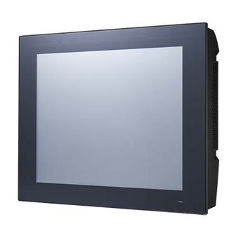
Page 17: External View
**1 x USB 2.0 (for connecting the motherboard and touch controller) External View The front of PPC-6151C/6171C/6191C is a flat panel LCD screen enclosed in an alu- minum frame. (When placed upright on a desk, the PPC-6151C/6171C/6191C front panel appears as shown below.) PPC-6151C/6171C/6191C-RTAE Off (S3, S4, S5): orange;... - Page 18 1. Air outlets 2. Antenna holes 3. Quick installation clip (1) 4. Panel mount bracket holes (10 for PPC-6151C/6171C and 12 for PPC-6191C) 5. Air inlets PPC-6151C/6171C/6191C User Manual...
-
Page 19: Dimensions
Dimensions 379.31 Unit: mm 103.60 391.40 7.50 145.70 100.00 75.00 382.00 Cutout Figure 1.1 PPC-6151C Dimensions PPC-6151C/6171C/6191C User Manual... - Page 20 425.00 unit: mm 107.60 437.00 7.50 168.58 100.00 75.00 427.00 Cutout Figure 1.2 PPC-6171C Dimensions PPC-6151C/6171C/6191C User Manual...
- Page 21 442.00 unit: mm 107.48 454.00 7.50 100.00 177.00 75.00 444.00 Cutout Figure 1.3 PPC-6191C Dimensions Fixed VESA screw specification: M4; screw depth: 8 mm/0.31 in (Max) PPC-6151C/6171C/6191C User Manual...
- Page 22 Warning! Use a suitable mounting apparatus to avoid risk of injury. PPC-6151C/6171C/6191C User Manual...
-
Page 23: Chapter 2 System Installation And Setup
Chapter System Installation and Setup Anti-Static Precautions Installation Procedures PPC-6151C/6171C/6191C-RTAE Motherboard Installation PPC-6151C/6171C/6191C-RMAE Motherboard Installation Component Setup Mount Installation Quick Installation... -
Page 24: Anti-Static Precautions
ESD from damaging the board or causing personal injury. Note! Refer to Chapter 1.3 (Chassis Comparison) to determine the chassis type, then refer to Chapters 2.3 and 2.4 (for PPC-6151C/6171C/6191C- RTAE and PPC-6151C/6171C/6191C-RMAE, respectively) for the installation guidelines. Warning! Failure to take appropriate ESD precautions during maintenance may result in permanent damage to the PPC and severe injury to the user. -
Page 25: Remove The Reinforced Board
2.2.2 Remove the Reinforced Board Remove the two screws on the reinforced board. 2.2.3 Install the PPC-MB-8260AE Motherboard The image below shows the PPC-MB-8260AE motherboard with PPC-6151C-RTAE. Resolution 1024 x 768 (24 bit) LED panel PWR +3.3 V Backlight level +3.3 V... - Page 26 Backlight level +3.3 V Brightness PWM level +5 V The image below shows the PPC-MB-8260AE motherboard with PPC-6191C-RTAE. Resolution 1280 x 1024 (24 bit) LED panel PWR +5 V Backlight level +3.3 V Brightness PWM level +3.3 V PPC-6151C/6171C/6191C User Manual...
- Page 27 Using the four screws provided in the accessory box, secure the motherboard to the motherboard frame (motherboards must be purchased separately). And connect the ATX cable. Note! Please refer to the datasheet when selecting the motherboard type in order to ensure optimum performance, maximum security, and sufficient air circulation. PPC-6151C/6171C/6191C User Manual...
-
Page 28: Connect The Motherboard Wires
2.2.4 Connect the Motherboard Wires PPC-6151C/6171C/6191C-RTAE and PPC-MB-8260AE assembly is demonstrated below: 1. LVDS 2. Backlight 3. SYS FAN1 4. SYS FAN2 5. HDD conn. 6. Touch 7. DIO 8. COM3 9. COM4 15. LED conn. 10. COM5 14. SPEAKER 11. -
Page 29: Install The Ppc-Mb-610 Motherboard
1. The COM cable and DIO cable are the same. 2. The cable connection is based on the motherboard specifications. 2.2.5 Install the PPC-MB-610 Motherboard The image below shows the PPC-MB-610 motherboard with PPC-6151C-RTAE. Resolution 1024*768(24bit) LED panel PWR +3.3V Backlight level +3.3V... - Page 30 The image below shows the PPC-MB-610 motherboard with PPC-6171C-RTAE. Resolution 1280*1024(24bit) LED panel PWR Backlight level +3.3V Brightness PWM level The image below shows the PPC-MB-610 motherboard with PPC-6191C-RTAE. Resolution 1280*1024(24bit) LED panel PWR Backlight level +3.3V Brightness PWM level +3.3V PPC-6151C/6171C/6191C User Manual...
- Page 31 Using the four screws provided in the accessory box, secure the motherboard to the motherboard frame (motherboards must be purchased separately). PPC-6151C/6171C/6191C User Manual...
-
Page 32: Connecting The Motherboard Wires
2.2.6 Connecting the Motherboard Wires PPC-6151C/6171C/6191C-RTAE and PPC-MB-610 assembly. 1.LVDS 2.Backligh 3.System Fan 4.Touch 8.SATA 5.ATX 20PIN 9.ATX 4PIN 6.DIO&COM3-5 10.LED 11.Speaker 7.Power Bu on PPC-6151C/6171C/6191C User Manual... - Page 33 1.LVDS 3.System Fan 2.Backligh 4.Touch 5.ATX 20PIN 6.DIO&COM3-5 7.Power Bu on 9.ATX 4PIN 8.SATA 11.Speaker 10.LED Internal complete connec ng picture PPC-6151C/6171C/6191C User Manual...
-
Page 34: Ppc-6151C/6171C/6191C-Rmae Motherboard Installation
PPC-6151C/6171C/6191C-RMAE Motherboard Installation 2.3.1 Install the Mini-ITX Motherboard (AIMB-275) The image below shows the AIMB-275 motherboard with PPC-6151C-RMAE. Resolution 1024 x 768 (24 bit) LED panel PWR +3.3 V JP2(4-6) Backlight level +3.3 V JP2(3-5) Brightness PWM level +3.3 V... - Page 35 The image below shows the AIMB-275 motherboard with PPC-6171C-RMAE. Resolution 1280 x 1024 (24 bit) LED panel PWR +5 V JP2(4-6) Backlight level +3.3 V JP2(1-3) Brightness PWM level +5 V PPC-6151C/6171C/6191C User Manual...
- Page 36 The image below shows the AIMB-275 motherboard with PPC-6191C-RMAE. Resolution 1280 x 1024 (24 bit) LED panel PWR +5 V JP2(4-6) Backlight level +3.3 V JP2(3-5) Brightness PWM level +3.3 V PPC-6151C/6171C/6191C User Manual...
- Page 37 Retrieve the I/O bracket from the AIMB-275 accessory box. Remove the I/O port blades. Take off the I/O port blades Install the motherboard I/O bracket into the chassis. PPC-6151C/6171C/6191C User Manual...
-
Page 38: Connect The Motherboard Wires
Use four screws from the accessory box to secure the motherboard in place. 2.3.2 Connect the Motherboard Wires PPC-6151C/6171C/6191C-RMAE and AIMB-275 assembly. 1. SATA conn. 2. CPU fan 3. SYS fan 1 10. Daughter board Power 4. PS_ON conn. 11.Touch conn. - Page 39 Speaker cable main board daughter board Note! Please refer to the PPC-6151C/6171C/6191C selection guide when selecting the motherboard type in order to ensure optimum perfor- mance, maximum security, and sufficient air circulation. The cable connection is based on the motherboard specifications.
- Page 40 Retrieve DC bracket screws from the accessory box and secure the DC bracket in place. Note! For the PPC-6151C/6171C/6191C model, users are advised not use the DC port on the motherboard. PPC-6151C/6171C/6191C User Manual...
-
Page 41: Connect The Daughter Board And Motherboard Using A Cable
Connect the motherboard. Note! Use a DP cable to connect the motherboard DP port and the chassis DP input port. Use a USB cable to connect one of the motherboard USB ports. The motherboards must have a DP port. PPC-6151C/6171C/6191C User Manual... -
Page 42: Component Setup
Exercise caution when handling the motherboard CPU pins. Refer to the datasheet when selecting the motherboard CPU. Note! After CPU installation, ensure the CPU surface is covered in thermal grease. (Thermal grease is included in the PPC-MB-8260AE mother- board accessory box.) PPC-6151C/6171C/6191C User Manual... -
Page 43: Cpu Cooler Installation
2.4.3 Memory Installation 1). Insert the memory card into the slot at a 45-degree angle. The gold fingers on the edge of the card must be completely inserted into the slot to ensure a secure connection. 45° PPC-6151C/6171C/6191C User Manual... -
Page 44: Hdd Installation
2) When the card is in the slot, apply firm pressure to the card until the clamps on the side click and lock the card into place. 2.4.4 HDD Installation Unscrew the four screws indicated in the image below. Then remove the HDD bracket. PPC-6151C/6171C/6191C User Manual... -
Page 45: Wi-Fi Module Installation
Wi-Fi Module Installation In the procedures listed below for installing a wireless LAN card, a PPC-WLAN-C1E motherboard is used in the example images. Attach the wireless LAN card to the bracket using the screws provided with the Wi-Fi module. PPC-6151C/6171C/6191C User Manual... - Page 46 Insert the wireless card into the appropriate mainboard slot. Then secure the card in place using a screws provided in the accessory box. Connect the cables of the wireless LAN card to the antenna holder. Note the installation direction of the cable end and nut/washer. PPC-6151C/6171C/6191C User Manual...
- Page 47 Lock the assembled antenna holder onto the machine. Then connect the cable to the wireless LAN card. Install the bracket and then replace the rear cover (see Section 2.5.7). Attach the wireless module antenna to complete installation. PPC-6151C/6171C/6191C User Manual...
-
Page 48: Expansion Card Installation
2.4.6 Expansion Card Installation Insert the PCI riser card (included in the PPC-6151C/6171C/6191C accessory box) into the slot and secure it in place using two screws. One PCIe x4 and two PCI riser cards are provided in the PPC-6151C/6171C/6191C accessory box, allowing users to customize the system according to their requirements. -
Page 49: Rear Cover Installation
Please refer to the above figures for rear cover installation. Align the left and right bottom corners of rear cover and front panel (refer to the red circles shown). Follow the direction of the red arrow for installation. PPC-6151C/6171C/6191C User Manual... -
Page 50: Mounting The System
Figure 2.1 Wall Mount Plate Insert four M4 screws into the holes on the panel PC and tighten them to secure the bracket to the rear panel. Figure 2.2 Screw Locations on the Rear Panel PPC-6151C/6171C/6191C User Manual... - Page 51 To mount the panel PC on a wall, align the wall mount bracket attached to the panel PC with the wall mount plate on the wall. Slide the panel PC downwards to hang the bracket on the mount plate. Figure 2.3 Mounting the Panel PC on a Wall PPC-6151C/6171C/6191C User Manual...
-
Page 52: Arm Mounting
Figure 2.4 Securing the Panel PC 2.5.2 Arm Mounting PPC-6151C / 6171C / 6191C can be mounted on a VESA-compliant arm mount with a 100 mm (3.9 in) interface pad. To secure the panel PC to an arm mount, follow the steps below. -
Page 53: Stand Mounting
Use four M4 x 8L screws to secure the VESA bracket to the panel PC. Users can choose between a 75 x 75 mm or 100 x 100 mm (2.95 x 2.95 in/3.9 x 3.9 in) VESA mount according to their requirements. Figure 2.6 VESA Mount Screw Holes PPC-6151C/6171C/6191C User Manual... - Page 54 Use the four M4 x 8L screws to secure the base plate to the mount stand. Figure 2.7 Securing the VESA Mount Base Use four M4 x 6L screws to secure the mount stand to the VESA mount bracket. Figure 2.8 Securing the VESA Mount Bracket PPC-6151C/6171C/6191C User Manual...
- Page 55 Use one M4 x 5L screw to secure the stand mount hinge cover. Figure 2.9 Securing the Stand Mount Hinge Cover Figure 2.10 Completed Stand Mount PPC-6151C/6171C/6191C User Manual...
-
Page 56: Panel Mounting
Put the machine into the cabinet and get the wall mount brackets. Panel mount bracket Fix the machine in place by tightening the screws. Panel mount bracket Replace the plastic plugs according to the arrow and hookup machine. Screw Fix the machine in place by tightening the screws. PPC-6151C/6171C/6191C User Manual... -
Page 57: Quick Installation
Users can independently complete the panel wall mount installation by following the quick installation procedures listed below. Loosen the two screws at the base (see the figure below). Push the machine into a gap in the wall. The spring hook will lock the machine into the wall. PPC-6151C/6171C/6191C User Manual... - Page 58 Lock the hook screw on the rear to secure the machine in place. Note! According to the quick installation guide, the recommended mount thick- ness is no more than 2 mm (.079 in). For other situations, the recom- mended thickness is 6 mm or less (.236 in). PPC-6151C/6171C/6191C User Manual...
-
Page 59: Appendix Apci/Pcie Riser Card
Appendix PCI/PCIE Riser Card... -
Page 60: Riser Card Introduction
Riser Card Introduction A.1.1 PPCB-003 PCI Riser Card The total current load provided by the PPC-6151C/6171C/6191C PCI slot does not exceed 20 W. Additional details are provided below. -12 V 0.1A +12 V 0.5A +5 V +3.3 V 2.5A +3.3 VSB 0.25A... -
Page 61: Eamb-Be02 2 X Pcie X 1 Riser Card
A.1.3 EAMB-BE02 2 x PCIe x 1 Riser Card The total current load provided by the PPC-6151C/6171C/6191C PCIe slot does not exceed 25 W. Additional details are provided below. +12 V 2.1A +3.3 V +3.3 VSB 0.375A A.1.4 EAMB-BE03 1 x PCIe x 1+1 x PCI Riser Card The total current load provided by the PPC-6151C/6171C/6191C PCIe and PCI slot does not exceed 25 W. -
Page 62: Eamb-Be17 2 X Pcie X 8 Riser Card (For Ppc-Mb-610(U) Only)
A.1.5 EAMB-BE17 2 x PCIe x 8 Riser Card (for PPC-MB-610(U) only) The total current load provided by the PPC-6151C/6171C/6191C PCIe slot does not exceed 25 W. Additional details are provided below. +12 V 2.1A +3.3 V +3.3 VSB 0.375A... - Page 63 PPC-6151C/6171C/6191C User Manual...
- Page 64 No part of this publication may be reproduced in any form or by any means, such as electronically, by photocopying, recording, or otherwise, without prior written permission from the publisher. All brand and product names are trademarks or registered trademarks of their respective companies. © Advantech Co., Ltd. 2020...
Need help?
Do you have a question about the PPC-6151C and is the answer not in the manual?
Questions and answers