
Related Manuals for Advantech PPC-3100-RE9A


Summary of Contents for Advantech PPC-3100-RE9A
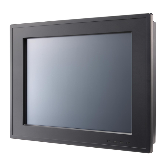
- Page 1 User Manual PPC-3100-RE9A PPC-3120-RE9A 10.4"/12.1" Color TFT LCD Panel PC with Intel® Atom™ E3940 Processor...
- Page 2 No part of this manual may be reproduced, copied, translated, or transmitted in any form or by any means without the prior written permission of Advantech Co., Ltd. The information provided in this manual is intended to be accurate and reliable.
- Page 3 (ESD) or electromagnetic interference (EMI) leakage, we strongly recommend using CE-compliant industrial enclosure products. Technical Support and Assistance Visit the Advantech website at http://support.advantech.com to obtain the latest product information. Contact your distributor, sales representative, or Advantech's customer service center for technical support if you need additional assistance. Please have the following information to hand before calling: –...
- Page 4 ATTENTION: Ce produit n’est pas un jouet et devrait être gardé hors de la por- tée des enfants. DISCLAIMER: These instructions are provided in accordance with IEC 704-1 standards. Advantech disclaims all responsibility for the accuracy of any state- ments contained herein. PPC-3100/3120 User Manual...
- Page 5 Safety Precaution - Static Electricity Follow the simple precautions below to protect yourself from harm and the products from damage. To avoid electrical shock, always disconnect the power from the PC chassis before manual handling. Do not touch any components on the CPU card or other cards while the equipment is powered on.
- Page 6 PPC-3100/3120 User Manual...
-
Page 7: Table Of Contents
Front Panel....................2 Figure 1.1 Front Panel ..............2 Rear Panel ....................3 Figure 1.2 Rear Panel..............3 Dimensions ....................3 Figure 1.3 PPC-3100-RE9A Dimensions........3 Figure 1.4 PPC-3120-RE9A Dimensions........4 Specifications .................... 4 Ordering Information ................. 5 Chapter System Installation and Setup ...7... - Page 8 Watchdog Timer Programming Example ..........46 PPC-3100/3120 User Manual viii...
-
Page 9: Chapter 1 General Information
Chapter General Information Introduction Specifications Dimensions... -
Page 10: Introduction
Introduction Advantech's PPC-3100/3120-RE9A is an all-in-one lightweight panel PC equipped with a 10.4”/12.1” TFT LCD. Powered by an Intel® Atom™ E3940 processor, PPC- 3100/3120-RE9A provides excellent performance, memory, graphics, and peripheral I/O support in a compact, fanless, embedded system. Built for high durability, PPC- 3100/3120-RE9A features a flat touchscreen with IP65 ingress protection and die- cast aluminum alloy enclosure. -
Page 11: Rear Panel
Rear Panel The PPC-3100/3120-RE9A rear panel features four VESA mount holes (75 x 75 mm), as shown in Figure 1.2. Figure 1.2 Rear Panel Dimensions Figure 1.3 PPC-3100-RE9A Dimensions PPC-3100/3120 User Manual... -
Page 12: Specifications
Figure 1.4 PPC-3120-RE9A Dimensions Specifications PPC-3100-RE9A PPC-3120-RE9A LCD Panel 10.4” 12.1” Display Type TFT LCD TFT LCD Max. Resolution 800 x 600 1024 x 768 Brightness Color 262k/16.2M 262k/16.2M Pixel Pitch 0.264 (H) x 0.264 (V) 0.240 (H) x 0.240 (V) -
Page 13: Ordering Information
HDD: 64 G SSD OS: Windows 7 (64 bit) Software: Burn-In Test 8.1 Ordering Information Part Number Description Image PPC-3100-RE9A Panel PC with Intel® Atom™ E3940 PPC-3120-RE9A processor Power adapter 100 ~ 240 V , 90 W, 96PSA-A90W19OT-1 19V with PFC... - Page 14 PPC-174T-WL-MTE Wall mount kit PPC-Stand-A1E Stand kit PPC-3100/3120 User Manual...
-
Page 15: Chapter 2 System Installation And Setup
Chapter System Installation and Setup Quick System Tour Memory Card Installation HDD Installation mSATA Installation Wireless LAN Card Installation Mounting the System... -
Page 16: Quick System Tour
Quick System Tour Before setting up the panel PC, take a moment to identify the locations of the device controls, drives, connectors, and ports (as shown in Figure 2.3). When placed upright, the PPC-3100/3120-RE9A front panel should appear as shown in Figure 2.1. Figure 2.1 Panel PC Front View Figure 2.2 Panel PC Rear View PPC-3100/3120 User Manual... -
Page 17: Installation Procedures
Install SATA HDD or mSATA storage Install a memory card Install peripheral devices Mount the panel PC Configure the system 2.2.1 HDD Installation Install a SATA HDD or mSATA storage PPC-3100-RE9A Unscrew the eight retention screws and remove the rear cover. PPC-3100/3120 User Manual... - Page 18 Unscrew the six retention screws and remove the HDD cover. Unscrew the four retention screws and remove the HDD bracket. Install a SATA HDD and affix it in place using four retention screws. PPC-3100/3120 User Manual...
- Page 19 Connect the SATA cable and replace the HDD bracket. Route the SATA cable. Connect the SATA cable to the motherboard. PPC-3100/3120 User Manual...
- Page 20 Replace the HDD cover and affix it in place using five retention screws. Secure the SATA cable with the line buckle and the close the rear cover. PPC-3120-RE9A Unscrew the eight retention screws and remove the rear cover. PPC-3100/3120 User Manual...
- Page 21 Unscrew the six retention screws and remove the HDD cover. Unscrew the four retention screws and remove the HDD bracket. Install a SATA HDD and affix in place using four retention screws. PPC-3100/3120 User Manual...
- Page 22 Connect the SATA cable and replace the HDD bracket Connect the SATA cable to the motherboard and replace the HDD cover. PPC-3100/3120 User Manual...
-
Page 23: Msata Installation
2.2.2 mSATA Installation Insert the mSATA card into the socket. Secure the mSATA card in place using the two retention screws provided in the accessory box. 2.2.3 Memory Card Installation Remove the rear cover and HDD cover. Then unscrew the six retention screws to open the heatsink. - Page 24 Insert the memory card into the slot highlighted in red in the image below. Next, install the thermal pads for the memory card and CPU provided in the accessory box. PPC-3100/3120 User Manual...
-
Page 25: Wireless Lan Module Installation
2.2.4 Wireless LAN Module Installation 2.2.4.1 Full-Size Mini PCIe Card Installation Insert a full-size mini PCIe card into the socket. Secure the card in place using the two retention screws provided in the accessory box (the red circles in the image below indicate the locations for the screws). - Page 26 Connect the antenna cables and affix them to the brackets. Please note the cable routing shown in the image below. Remove the two plugs at the top of the rear cover. Install the external antennas. PPC-3100/3120 User Manual...
-
Page 27: Mounting The System
Mounting the System Warning! When mounting the panel PC, more than one person should perform the installation to prevent accidental damage to the panel or personal injury. Le comité constate qu’el-nasr mounting, plus d’une personne installa- tion to prevent the cadre accidental damage or personal injury. The panel PC supports various mount options, as listed below. - Page 28 Screw locations on the rear panel Warning! Ensure that the thread depth of the screws on the rear panel does not exceed 4 mm. Assurez-vous que la profondeur du filetage des vis sur le panneau arri- ère ne dépasse pas 4 mm. To mount the panel PC on a wall, align the wall mount bracket attached to the panel PC with the wall mount plate on the wall and slide the panel PC down- wards to hang the bracket on the mount plate, as shown below.
-
Page 29: Panel Mounting
Secure the panel PC in place by tightening the screws in the wall mount bracket. Securing the panel PC 2.3.2 Panel Mounting To mount the flat bezel panel PC into a panel, follow the steps below. Prepare a panel cutout according to the panel PC dimensions. For PPC-3100: 265 x 210 mm (10.43 x 8.26 in) For PPC-3120: 311 x 240 mm (12.24 x 9.44 in) Install the panel PC in the cabinet and retrieve the eight hook brackets provided... - Page 30 Insert the hook brackets into the holes in the direction of the arrows shown in the image below. Hook bracket location Tighten the screws to affix the panel PC in place. Fasten the hook bracket Panel mount rear view PPC-3100/3120 User Manual...
-
Page 31: Arm Mounting
2.3.3 Arm Mounting PPC-3100/3120-RE9A can be mounted on a VESA-compliant arm mount with a 100 mm interface pad. To affix the panel PC to an arm mount, follow the steps below. Refer to the installation instructions for the mounting arm to correctly mount the arm onto a surface as a base. -
Page 32: Stand Mounting
2.3.4 Stand Mounting Before stand mounting, check that the following items were included with the product: To mount the panel PC onto a stand, follow the steps below Use four M4 x 8L screws to affix the VESA bracket to the panel PC. Users can choose between a 75 x 75 mm or 100 x 100 mm VESA mount according to their requirements. - Page 33 Use four M4 x 8L screws to secure the base plate to the mount stand. Securing the VESA mount base Use four M4 x 6L screws to secure the mount stand to the VESA mount bracket. Securing the VESA mount bracket PPC-3100/3120 User Manual...
- Page 34 Use one M4 x 5L screw to secure the stand mount hinge cover. Securing the stand mount hinge cover Completed stand mount PPC-3100/3120 User Manual...
-
Page 35: Chapter 3 Jumper Settings
Chapter Jumper Settings Motherboard Layout Jumpers and Connectors External COM Ports and Pin Definitions... -
Page 36: Motherboard Layout
Motherboard Layout The layout of the motherboard, including the internal peripheral connectors, is shown below. The internal peripheral connectors are accessible when the motherboard is outside of the chassis. Motherboard layout diagram Connectors Functions LPC Conn. LCD Backlight SATA Power CN13 COM4 CN14... -
Page 37: Jumper And Connector Settings
Jumper and Connector Settings Icon RTC Select (2-3) Normal Default* (3-4) Clear CMOS Backlight Enable Icon Power Select (1-2) Default* (2-3) 3.3V Backlight PWM Icon Power Select (1-2) Default* (2-3) 3.3V PPC-3100/3120 User Manual... - Page 38 Icon Touch Power Select (1-2) 3.3VSB Default* CN16 COM1/COM2 RING Type Select (1-3)/(2-4) COM1/COM2 RI Default* (3-5)/(4-6) COM1/COM2 5V (7-9)/(8-10) COM1/COM2 12V Icon AT/ATX Select ATX Power Default* AT Power Icon Panel Resolution 1,2,3,4 ON 800*600 24Bits Default* 1 OFF; 2,3,4 ON 1024*768 24Bits PPC-3100/3120 User Manual...
-
Page 39: External Com Ports Pin Definition
External COM Ports Pin Definition 3.3.1 COM1 ~ COM5: RS232 COM1 and COM2 are set to RI signals by default, but can be set as 5V/12V output via a jumper (CN16). COM1/COM2 COM3/COM4 RING or 5V/12V output RING PPC-3100/3120 User Manual... -
Page 40: Com3: Rs-422/485 With Isolation
3.3.2 COM3: RS-422/485 with Isolation RS422 RS485 PPC-3100/3120 User Manual... -
Page 41: Chapter 4 Software Setup
Chapter Software Setup Driver Installation BIOS Setup Program... -
Page 42: Driver Installation
Driver Installation Before installing software on the panel PC, install the corresponding drivers to ensure full functionality. All drivers can be downloaded from the Advantech website http://www.advantech.com BIOS Setup Program 4.2.1 Entering BIOS Setup When the power is turned on, press the <Del> button to enter BIOS setup screen. -
Page 43: Adjustment Of Lcd Brightness
4.2.2 Adjustment of LCD Brightness Select “North Bridge” in “Chipset” tab. Then select “LCD Control”. PPC-3100/3120 User Manual... - Page 44 Select “Brightness Mode Control”. There are six brightness levels to choose from in the “Brightness Control” menu. PPC-3100/3120 User Manual...
-
Page 45: Com2 Mode Selection (Rs232/Rs422/Rs485)
4.2.3 COM2 Mode Selection (RS232/RS422/RS485) Select “NCT6116D Super IO Configuration” in the “Advanced” tab. Select the “Serial Port 3 Configuration” option. PPC-3100/3120 User Manual... - Page 46 Select “Serial Port 3 Mode” and double click to set the COM3 operation mode to RS422 or RS485. When the COM3 mode is set to RS485, the “RS485 Auto Flow” function can be Enabled/Disabled. PPC-3100/3120 User Manual...
-
Page 47: Os Selection
When the COM3 mode is set to RS485, the “Serial Port3 Terminal” can be Enabled/Disabled. 4.2.4 OS Selection Select “South Bridge” in the “Chipset” tab. PPC-3100/3120 User Manual... -
Page 48: Bios At & Atx Setup
The “OS Selection” option allows user to select between Windows, Android, and Linux OS. 4.2.5 BIOS AT & ATX Setup Select “South Cluster Configuration” in the “Chipset” tab. PPC-3100/3120 User Manual... - Page 49 Select the “Miscellaneous Configuration” option. In “Restore AC Power Loss”, set the AT Mode as “Power On” and the ATX Mode as “Power Off”. PPC-3100/3120 User Manual...
-
Page 50: Wake-On-Lan
4.2.6 Wake-on-LAN Select “South Cluster Configuration” in the “Chipset” tab. Select the “Miscellaneous Configuration” option. PPC-3100/3120 User Manual... - Page 51 Set “Wake-By-PCIE” option to Enabled. PPC-3100/3120 User Manual...
- Page 52 PPC-3100/3120 User Manual...
-
Page 53: Appendix A Watchdog Timer Programming
Appendix Watchdog Timer Programming... - Page 54 Watchdog Timer Programming Example The watchdog timer is provided to ensure that standalone systems can always recover from catastrophic CPU failures and crashes. Such events may have been caused by external EMI or a software bug. If the CPU is malfunctioning, the watch- dog timer performs a hardware reset to return the system to a previous state.
- Page 55 ;----------------------------------------------------------------------------- ;Set WDT timeout value ;----------------------------------------------------------------------------- MOV DX, 2EH MOV AL, F1H OUT DX, AL MOV DX, 2FH MOV AL, 05H OUT DX, AL; set timeout value as 5s; 00 = timeout disabled ;----------------------------------------------- ;Exit the extended function mode ;---------------------------------------------- MOV DX, 2EH MOV AL, AAH OUT DX, AL...
- Page 56 PPC-3100/3120 User Manual...
- Page 57 PPC-3100/3120 User Manual...
- Page 58 No part of this publication may be reproduced in any form or by any means, such as electronically, by photocopying, recording, or otherwise, without prior written permission from the publisher. All brand and product names are trademarks or registered trademarks of their respective companies. © Advantech Co., Ltd. 2018...
Need help?
Do you have a question about the PPC-3100-RE9A and is the answer not in the manual?
Questions and answers