Table of Contents
Advertisement
Quick Links
Our company network supports you worldwide with offices in Germany, Austria,
Switzerland, Great Britain and the USA. For more information please contact:
FORTEC Elektronik AG
Hauptniederlassung
Lechwiesenstr. 9
86899 Landsberg am Lech
Telefon:
+49 (0) 8191 91172-0
Telefax:
+49 (0) 8191 21770
E-Mail:
sales@fortecag.de
Internet:
www.fortecag.de
FORTEC Elektronik AG
Büro Wien
Nuschinggasse 12
A-1230 Wien
Telefon:
+43 1 8673492-0
Telefax:
+43 1 8673492-26
E-Mail:
office@fortec.at
Internet:
www.fortec.at
The information contained in this document has been carefully researched and is, to the best
of our knowledge, accurate. However, we assume no liability for any product failures or
damages, immediate or consequential, resulting from the use of the information provided
herein. Our products are not intended for use in systems in which failures of product could
result in personal injury. All trademarks mentioned herein are property of their respective
owners. All specifications are subject to change without notice.
Manual
PPC-6120
Advantech
FORTEC Elektronik AG
Büro West
Hohenstaufenring 55
50674 Köln
Telefon:
Telefax:
E-Mail:
Internet:
ALTRAC AG
(Tochter der FORTEC):
Bahnhofstraße 3
CH-5436 Würenlos
Telefon:
Telefax:
E-Mail:
Internet:
+49 (0) 221 272 273-0
+49 (0) 221 272 273-10
west@fortecag.de
www.fortecag.de
+41 (0) 44 7446111
+41 (0) 44 7446161
info@altrac.ch
www.altrac.ch
Advertisement
Table of Contents

Related Manuals for Advantech PPC-6120


Summary of Contents for Advantech PPC-6120
- Page 1 Manual PPC-6120 Advantech Our company network supports you worldwide with offices in Germany, Austria, Switzerland, Great Britain and the USA. For more information please contact: FORTEC Elektronik AG FORTEC Elektronik AG Hauptniederlassung Büro West Lechwiesenstr. 9 Hohenstaufenring 55 86899 Landsberg am Lech 50674 Köln...
- Page 2 User Manual PPC-6120 Intel® Core™ i / Celeron® based Panel PC with a 12.1" Color TFT...
- Page 3 No part of this manual may be reproduced, copied, translated or transmitted in any form or by any means without the prior written permission of Advantech Co., Ltd. Information provided in this manual is intended to be accurate and reliable. How- ever, Advantech Co., Ltd.
-
Page 4: Declaration Of Conformity
This product has passed the CE test for environmental specifications when shielded cables are used for external wiring. We recommend the use of shielded cables. This kind of cable is available from Advantech. Please contact your local supplier for ordering information. -
Page 5: Safety Instructions
The sound pressure level at the operator's position according to IEC 704-1:1982 is no more than 70 dB (A). DISCLAIMER: This set of instructions is given according to IEC 704-1. Advantech disclaims all responsibility for the accuracy of any statements contained herein. - Page 6 Battery Information Batteries, battery packs and accumulators should not be disposed of as unsorted household waste. Please use the public collection system to return, recycle, or treat them in compliance with the local regulations. PPC-6120 User Manual...
- Page 7 PPC-6120 User Manual...
-
Page 8: Table Of Contents
Figure 2.16 Assemble wireless card and antenna...... 17 Figure 2.17Replace the HDD module......... 18 Figure 2.18View of assemble antenna ........18 Installing PPC-6120-EXPE..............19 Figure 2.19PPC-6120-EXPE module ......... 19 Figure 2.20Remove riser card door ..........19 Figure 2.21Assemble riser card..........20 Figure 2.22Complete assemble expansion kits ...... - Page 9 Entering BIOS Setup ..............32 4.2.2 Adjustment of LCD Brightness............ 33 4.2.3 COM5 Mode Selection (RS422/RS485) ........35 4.2.4 COM5 RS485 Terminate Selection ..........36 4.2.5 Wake on LAN................37 4.2.6 AT & ATX Setting................ 39 PPC-6120 User Manual viii...
-
Page 10: Chapter 1 Overview
Chapter Overview This chapter gives basic information about the PPC-6120. Sections include: Introduction Specifications Dimensions... -
Page 11: Introduction
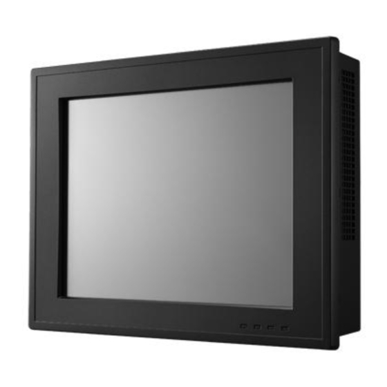
Introduction Advantech’s PPC-6120 is a 4th Generation Intel Core™ i / Celeron based Panel PC with a 12" color TFT LCD. It features extremely high computing power, various con- nectors, and can be installed in virtually any application. In addition, its user-friendly interface makes it a great host for information appliances. -
Page 12: Power Specifications
0 ~ 50°C (32 ~ 122°F) Temperature Storage Temperature -20 ~ 60°C (-4 ~ 140°F) Relative Humidity 10 ~ 95% @ 40°C (Non-condensing) Shock 10 G peak acceleration (11 ms duration) Vibration 5 ~ 500 Hz 1 G RMS PPC-6120 User Manual... -
Page 13: Certification
CB, CCC, BSMI, UL 1.2.6 IP Grade Front Panel Dust-Proof & IP65 compliant Water-Proof Remark 1: Power consumption (PPC-6120): Test Test Configuration Test System Memory: Transcend 8G DDR3 1600 * 1 Win 7 (64bit) Burn-in 7.0 HDD: Seageat 500G 2.5”* 1 Win 8 (64bit) IO: COM Port RS232 loopback x4, USB3.0 device *4... -
Page 14: Dimensions
Dimensions Figure 1.1 Dimensions PPC-6120 User Manual... - Page 15 Note! Specification of mounting VESA screw: M4. Depth of screw hole: 6 mm (Max.). Warning! Use suitable mounting apparatus to avoid risk of injury. PPC-6120 User Manual...
-
Page 16: Chapter 2 System Setup
Chapter System Setup Sections include: A Quick Tour Installation Procedures Installing Memory Installing HDD Installing Mini SATA Installing Wireless LAN Installing Expansion Card Installing Hook Quick Installation of PPC-6120... -
Page 17: A Quick Tour
Network status indicator (LAN LED) HDD status indicator (HDD LED) Power status indicator (Power LED) LAN LED Status HDD LED POWER LED LAN1 LAN2 Green Yellow Yellow Power On (S0) (Operating, (Operating, (Operating, Green flashing) flashing) flashing) PPC-6120 User Manual... -
Page 18: Figure 2.2 Side View Of Panel Pc
Figure 2.2 Side View of Panel PC Antenna hole CPU cooler holes Hook hole for panel mount (8 holes) Speaker (left & right) PPC-6120 User Manual... -
Page 19: Figure 2.3 Io Connectors Of Panel Pc
B: Line Out C: USB 3.0 * 4 D: Gigabit Ethernet x 2 (supports iAMT 9.0) E: VGA Port F: Display Port 1.2 G: COM RS-232 x 4 H: DC inlet and AT/ATX switch I: RS422/485 (Isolation) PPC-6120 User Manual... -
Page 20: Installation Procedures
Connecting Keyboard and Mouse Connect the mouse and keyboard to the I/O connector of the panel PC. 2.2.3 Switching on Power The power switch is located on the lower right corner on the rear cover of the panel PPC-6120 User Manual... -
Page 21: Installing Cpu
Installing CPU Unfasten the screws on the rear cover (8 screws). Figure 2.5 Unfastening Screws on Rear Cover Unplug the switch wire from the main board and remove the rear cover. Figure 2.6 Unplugging Switch Wire PPC-6120 User Manual... -
Page 22: Figure 2.7 Remove Rear Cover
Remove rear cover. Figure 2.7 Remove rear cover Put the CPU in the CPU socket and fasten the securing bracket. Figure 2.8 CPU fasten in socket PPC-6120 User Manual... -
Page 23: Figure 2.9 Cpu Cooler
Take the cooler from the carton, note that thermal pad is assembled on the cooler. Figure 2.9 CPU cooler Place the cooler on the M/B frame and insert the cooler power cable. Figure 2.10 Assemble cooler PPC-6120 User Manual... -
Page 24: Installing Memory
Figure 2.11 Install Memory Installing HDD Follow section 2.3 step to remove rear cover. Remove the green tape and unfasten the four screws to take off HDD bracket. Figure 2.12 Loosen HDD bracket screws PPC-6120 User Manual... -
Page 25: Figure 2.13Fix Hdd In Hdd Brackets
Figure 2.13 Fix HDD in HDD brackets Replace the HDD bracket and plug in the power cable. Figure 2.14 Assemble HDD Attach the power cable to the main board. Replace the rear cover and secure it to finish the installation. PPC-6120 User Manual... -
Page 26: Installing Msata
(in accessory box) to be fixed into the position. Fix the antenna into the position as shown below (left & right). Figure 2.16 Assemble wireless card and antenna PPC-6120 User Manual... -
Page 27: Figure 2.17Replace The Hdd Module
Replace the HDD bracket. Figure 2.17 Replace the HDD module Connect the antenna to the wireless LAN card and attach the external antenna terminals. Then replace the rear cover to finish the installation. Figure 2.18 View of assemble antenna PPC-6120 User Manual... -
Page 28: Installing Ppc-6120-Expe
Take the PIC riser card as an example. Figure 2.19 PPC-6120-EXPE module Remove the screw that fixes the metal cover onto the back of PPC-6120, and then remove the cover. Figure 2.20 Remove riser card door... -
Page 29: Figure 2.21Assemble Riser Card
Figure 2.21 Assemble riser card Insert the desired card into the slot and use the screw to fix it. Replace the rear cover of PPC-6120-EXPE and use the screws (7 screws) to fix Figure 2.22 Complete assemble expansion kits Note! The size of PCI and PCIE card can not exceed 248mm long and 115mm wide. -
Page 30: Installing Hook
After the panel PC is installed in the cabinet, prepare the hook. Place the hook in the hole as the picture shows to hookup the panel PC. Screw Fasten the screw to fix the panel PC. Figure 2.23 Installing Hook PPC-6120 User Manual... -
Page 31: Quick Installation Of Ppc
Figure 2.24 Put Panel PC into Cabinet Use one hand to support the PC, while using the other to push the PC into the cabinet by pushing up the clamp with a screwdriver. Figure 2.25 Installing PC with Clamp PPC-6120 User Manual... -
Page 32: Figure 2.26Installing Hook
Once the panel PC is attached into the cabinet, use the hook to secure it. Figure 2.26 Installing Hook If you want to remove the panel PC, reverse the above steps. PPC-6120 User Manual... - Page 33 PPC-6120 User Manual...
-
Page 34: Jumpers And Connectors
Chapter Jumpers and Connectors Sections include: Jumpers and Connectors External COM Ports Pin Defini- tion... -
Page 35: Jumpers And Connectors
Internal USB 2.0 GPIO CN11 Touch RTC Select Touch Disable Select CN18 Light sense CN24 LED Board CN27 Speaker CN15 SATA Power CN14 COM Pin9 Power Select (COM1&COM2) CN25/CN26 Power Button AT/ATX Select DDR3 or DDR3L Select PPC-6120 User Manual... - Page 36 Touch Disable Graphic Panel Resolution (1-2)(5-6)(7-8) 1024*768 24bit Default* (1-2)(7-8) 1280*1024 24bit (1-2)(3-4)(5-6) 1366*768 18bit (1-2) 1920*1080 24bit CN14 Graphic COM1/2 RI Type Select (1-3)/(2-4) COM1/COM2 RI Default* (3-5)/(5-7) COM1/COM2 5V (4-6)/(6-8) COM1/COM2 5V (7-9)/(8-10) COM1/COM2 12V PPC-6120 User Manual...
-
Page 37: External Com Ports Pin Definition
Function For DDR3 1.5V Default* For DDR3L 1.35V AT/ATX Select ATX Power Default* AT Power External COM Ports Pin Definition Figure 3.2 COM Port PPC-6120 User Manual... - Page 38 Pin9 is set as RI signal in COM port by default, and could be set as 5V/12V output by Jumper Note! COM4 doesn't support RING function. COM1/COM2 COM3/COM4 RING or 5V/12V output RING(Only COM3) Pin9 is set as RI signal in COM port by default, and could be set as 5V/12V output by Jumper PPC-6120 User Manual...
- Page 39 (1) 8 data bits + 1 parity bit + 1stop bit (2) 8 data bits + 1 parity bit + 2 stop bits (3) 8 data bits + 2 stop bits PPC-6120 User Manual...
-
Page 40: Software Setup
Chapter Software Setup Sections include: Driver Installation BIOS Setup Program... -
Page 41: Driver Installation
Entering BIOS Setup When the power is turned on, press the <Del> key to enter BIOS setup screen. Whenever a change is made, press <F4> to save and exit; otherwise the settings will not be saved in the BIOS. PPC-6120 User Manual... -
Page 42: Adjustment Of Lcd Brightness
A. Manual Mode “LCD Brightness Control” is set to “Manual Mode” by default, which means you should adjust the brightness by yourself. Select “Brightness Manual Control” under “Brightness Control”. There are in all six brightness levels to choose. PPC-6120 User Manual... - Page 43 B. Dynamic Mode “LCD Brightness Control” is set to “Dynamic Mode”, which means LCD will auto- matically sense the light and adjust the brightness accordingly. PPC-6120 User Manual...
-
Page 44: Com5 Mode Selection (Rs422/Rs485)
4.2.3 COM5 Mode Selection (RS422/RS485) Select “Super IO Configuration” in “Advanced” tab. Select “Serial Port 5 Configuration”. You can select the mode of COM5 through “Serial Port5 Mode”. PPC-6120 User Manual... -
Page 45: Com5 Rs485 Terminate Selection
4.2.4 COM5 RS485 Terminate Selection Select “Super IO Configuration” in “Advanced” tab. Select Serial Port 5 Configuration and select Serial Port5 RS485 Terminate. PPC-6120 User Manual... -
Page 46: Wake On Lan
4.2.5 Wake on LAN A. Open wake on LAN function in windows 7. Select “ACPI Settings” in “Advanced” tab. Set “Wake on by PCIE Wake#” and “Wake on LAN” to “Enabled”. PPC-6120 User Manual... - Page 47 Save the settings and exit OS. Right-click “Computer” to select “Manage” to open “Computer Management” window. Click “Device Manager” and select “Network adapters”. Right-click the desired LAN port and select “Properties” to open “Realtek PCIe GBE Family Control- ler Properties” window. PPC-6120 User Manual...
-
Page 48: At & Atx Setting
Select “Power Management” tab in “Realtek PCIe GBE Family Controller Properties" window, then check “Allow this device to wake the computer”. 4.2.6 AT & ATX Setting Select "Chipset", then select "PCH-IO Configuration" PPC-6120 User Manual... - Page 49 Select below “Restore AC Power Loss”. PPC-6120 User Manual...
- Page 50 PPC-6120 User Manual...
- Page 51 No part of this publication may be reproduced in any form or by any means, electronic, photocopying, recording or otherwise, without prior written permis- sion of the publisher. All brand and product names are trademarks or registered trademarks of their respective companies. © Advantech Co., Ltd. 2014...
- Page 52 Our company network supports you worldwide with offices in Germany, Austria, Switzerland, Great Britain and the USA. For more information please contact: FORTEC Elektronik AG FORTEC Elektronik AG Hauptniederlassung Büro West Lechwiesenstr. 9 Hohenstaufenring 55 86899 Landsberg am Lech 50674 Köln Telefon: +49 (0) 8191 91172-0 Telefon:...
Need help?
Do you have a question about the PPC-6120 and is the answer not in the manual?
Questions and answers