Advertisement
S
HOWER AND
PLEASE REVIEW THIS ENTIRE MANUAL PRIOR TO INSTALLATION
MODEL #s
SHDR-1948723-##
SHDR-1948723L-##
SHDR-1948723R-##
SHDR-1960580-##
SHDR-1960580L-##
SHDR-1960580R-##
SHDR-1960723-##
SHDR-1960723L-##
SHDR-1960723R-##
IMPORTANT!
DreamLine
reserves the right to alter, modify or redesign products at any time without prior notice for the
®
purpose of product improvement and customer experience. Please refer to the model's web page on
DreamLine.com for the latest technical drawings, installation manuals, warranty information or additional
product details.
Do Not Return Product to the Store. Contact DreamLine® with any questions
Please contact DreamLine Customer Support
See DreamLine.com for hours of operation
MIRAGE_X_Shower_And_Tub_Installation_Manual_Ver2_072024
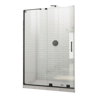
MIRAGE-X
T
D
I
UB
OOR
## = FINISH:
01 - Chrome
04 - Brushed Nickel
05 - Brushed Gold
09 - Matte Black
NSTALLATION
MEASUREMENTS
Model Size Height
48"
60"
Tub
1-866-731-2244
© 2024 DreamLine® All Rights Reserved
I
NSTRUCTIONS
Width
Min.
Max.
72"
44"
48"
72"
56"
60"
58"
56"
60"
Advertisement
Table of Contents

Related Manuals for Dreamline MIRAGE-X SHDR-1948723 Series


Summary of Contents for Dreamline MIRAGE-X SHDR-1948723 Series
- Page 1 ® purpose of product improvement and customer experience. Please refer to the model’s web page on DreamLine.com for the latest technical drawings, installation manuals, warranty information or additional product details. Do Not Return Product to the Store. Contact DreamLine® with any questions Please contact DreamLine Customer Support See DreamLine.com for hours of operation...
- Page 2 NOTES Record the following purchase information for your records or in the event you need to contact DreamLine ® Purchase Order Store/Vendor Number Purchased From OD Number Installation Date (optional) *found on the shipping box or label if available. SKU Number...
- Page 3 Table of Contents Section Title Page # ® ClearMax Coating Information Warnings and General Preparation Model Specific Preparation Tools Detailed Diagram of Shower and Tub Door Components Parts List Installation Steps 8-35 SafeStop™ Bumper Installation 15-16 Reversible L-Bar™ Installation 21-23 Bottom Roller Assembly Installation Guide Block Assembly Installation Re-Install Decorative Cover Plate...
-
Page 4: Important Product Information
Important Product Information WARNING DISCLOSURE STATEMENT IMPORTANT GENERAL PREPARATION • • The manufacturer reserves the right to alter, modify or redesign products any time without After opening all boxes and packages, read this introduction carefully. Check that all the prior notice for product improvement and customer experience. Please refer to the items are included in the package by marking off the components on the “Detailed manufacturer’s web page for the latest technical drawings, installation Diagram of Product Components”... - Page 5 Model Specific Preparation REQUIRED: 1-1/2” minimum threshold 1-1/2” minimum threshold ±0.0 ±0.0 ±0.0 ±0.0 ±0.0 ±0.0 The L-Bar™ is reversible. NOTE Tile Acrylic Contact the manufacturer of the base, tub or This manual will describe the threshold material with any questions shower/tub door installation using regarding the drilling of holes into their the Reversible L-Bar™...
- Page 6 Detailed Diagram on page 5 and parts list in this manual as a reference. Before discarding the carton, check for small hardware bags that may have fallen to the bottom of the box. If any parts are damaged or missing, please contact DreamLine ®...
- Page 7 Detailed Diagram of Shower/Tub Door Components Inline panel Door Right-hand door installation shown © 2024 DreamLine® All Rights Reserved...
-
Page 8: Parts List
Parts List MIRAGE_X_Shower_And_Tub_Installation_Manual_Ver2_072024... - Page 9 Parts List MIRAGE_X_Shower_And_Tub_Installation_Manual_Ver2_072024...
- Page 10 U-Channel (#17) on the panel side only. Tools Needed Decide on the handing of the shower door based on your bathroom NOTE configuration. The right-hand door installation will be shown as an example throughout this manual. © 2024 DreamLine® All Rights Reserved...
- Page 11 Drill a Ø3/16” hole throughout and then a Ø5/16” The Bottom Guide Rail (#03) NOTE hole through the top layer only. (Refer to the existing is made 2” larger than the model size: holes in the rail for an example) © 2024 DreamLine® All Rights Reserved...
- Page 12 Tools Needed Use a tape measure to align the rail parallel with the outside edge of NOTE the threshold. Mark the holes for drilling through the predrilled holes in the Bottom Guide Rail (#03). © 2024 DreamLine® All Rights Reserved...
- Page 13 Ø1/8”(3mm) hole and use the ST4.0 x 30mm Pan Head Screw (#16) NOTE ◾* For installation into a Tile Threshold: drill a Ø3/16”(4mm) hole up to the stud and use the ST4.0 x 40mm Pan Head Screw (#21) © 2024 DreamLine® All Rights Reserved...
- Page 14 Cutting the UChannel to the Height of the Panel Glass Cutting the UChannel to the Height of the Panel Glass NOTE NOTE Measure the height of the Stationary Panel Glass (#01) for your shower door model. Measure that same length on the UChannel (#17).
- Page 15 Leveling and Marking the UChannel ±0.0 ±0.0 Parts Needed Fig 6 Fig 6 Tools Needed Right-hand door installation shown © 2024 DreamLine® All Rights Reserved...
- Page 16 ST4.2 x 40mm Countersunk Screws (#07) NOTE ◾If no stud is present behind the wall: drill a Ø5/16”(7mm) hole and insert the Wall Anchors (#06) and use the ST4.2 x 40mm Countersunk Screws (#07). © 2024 DreamLine® All Rights Reserved...
- Page 17 ◾If no stud is present behind the wall: Extender driver bit recommended drill a Ø5/16”(7mm) hole and insert the Wall Anchors (#06) for screw installation. and use the ST4.2 x 40mm Countersunk Screw (#07) © 2024 DreamLine® All Rights Reserved...
- Page 18 The Adhesive installation method is shown. Attaching the bottom Bumper with a screw is optional. Follow the procedure shown in Step 7 for installing the bottom Bumper (#11) with the ST4.2 x 40mm Countersunk Screw (#07). © 2024 DreamLine® All Rights Reserved...
- Page 19 2” (50.8mm) Fig 9 Parts Needed Cut several 2” - 3” pieces of the PVC Glass Spacer 0.5mm (#14). DO NOT install one long continuous piece into the Bottom Guide Rail (#03). Tools Needed © 2024 DreamLine® All Rights Reserved...
- Page 20 Do not apply silicone in the UChannel or on the Bottom Guide Rail. The panel glass will be secured with a pinch vinyl in step 12 on Page 20. Fig 10 Save the remaining 2” pieces of the PVC Glass Spacer 0.5mm (#14) for later use. © 2024 DreamLine® All Rights Reserved...
- Page 21 Tools Needed The panel-side U-Channel (#17) will allow for up to 3/8” of out-of-plumb adjustment. NOTE Use a level to confirm that the Inline Panel Glass (#01) is installed plumb and level. © 2024 DreamLine® All Rights Reserved...
- Page 22 Fig 12 Parts Needed Start the Vertical Pinch Vinyl at the bottom of the UChannel. Insert the narrow edge of the vinyl between the Panel Glass and the UChannel, working upward. Trim any excess. © 2024 DreamLine® All Rights Reserved...
- Page 23 Reversible L-Shaped Bracket Step 1 Instructions for reversing Bracket direction (If needed) left-handed orientation Fig 13 Tools Needed left-to-right handed orientation shown © 2024 DreamLine® All Rights Reserved...
- Page 24 Reversible L-Shaped Bracket Step 2 Instructions for reversing Bracket direction (If needed) right-handed orientation Tools Needed Fig 13a left-to-right handed orientation shown © 2024 DreamLine® All Rights Reserved...
- Page 25 Tools Needed *The 0.5mm PVC Spacer (#30.4) for the L-Shaped Bracket Glass Holder (#30.11) is shipped flat and this NOTE piece must be folded around the top of the Inline Panel Glass (#11) during installation. © 2024 DreamLine® All Rights Reserved...
- Page 26 (See Fig 18.3 and 18.4) to adjust the angle of the Bracket (up to 3/16” (4mm)) in the desired NOTE direction. Hand tighten the M5 x 14.5 screws after adjustment is complete and replace the decorative cover. © 2024 DreamLine® All Rights Reserved...
- Page 27 Installing the Reversible L-Shaped Bracket (3 of 3) 0 - 1/16” (2mm) Fig 16 right-handed installation shown inside Tools Needed © 2024 DreamLine® All Rights Reserved...
- Page 28 To prevent glass-to-metal contact, insert a small piece (1/4” +/-) of the leftover PVC Glass Spacer 0.5mm (#14) between the end of the Bottom Channel Insert (#12) and the Inline Panel Glass (#01) as shown in Fig 16b. © 2024 DreamLine® All Rights Reserved...
- Page 29 Fig 18c Make certain that the bolts are facing inside the shower and the Bottom Roller Assemblies (#10) are inside installed squarely onto the glass as shown in Fig 18c. © 2024 DreamLine® All Rights Reserved...
- Page 30 Guide Block Assembly (#09). inside Parts Needed Fig 19 Tools Needed Use caution to prevent the door glass from making contact with the installed Inline Panel Glass or the wall during installation. © 2024 DreamLine® All Rights Reserved...
- Page 31 Use caution to prevent Parts Needed Fig 20 the unprotected edge of the door glass from making contact with the DO NOT completely disassemble the wall during installation. Guide Block Assembly (#09) during installation. © 2024 DreamLine® All Rights Reserved...
- Page 32 Roller Assemblies. Fig 21b Tools Needed Use shims beneath the Door Glass (#02) during adjustment to prevent the door glass from making contact with the Bottom Guide Rail (#03). © 2022 DreamLine® All Rights Reserved...
- Page 33 Re-Installing the Decorative Cover Plate 1/16” inside Parts Needed Fig 22 © 2024 DreamLine® All Rights Reserved...
- Page 34 Handle and Bulb Vinyl Installation Start attaching the Bumper Vinyl from the bottom of the Door Glass and work upward, pressing firmly. Fig 23 Parts Needed Fig 23 © 2024 DreamLine® All Rights Reserved...
- Page 35 Deflector Vinyl (#18) installed onto Door Glass Notching the Bulb inside Vinyl around the Sweep Bulb Vinyl Seal Parts Needed Fig 24 Right-hand installation shown as example Tools Needed inside © 2024 DreamLine® All Rights Reserved...
- Page 36 B= 1/4” (7mm) inline panel glass 1”(25mm) 1/4”(7mm) door glass top view of Vertical Vinyl Seal (#19) inside installed onto Door Glass Fig 25 Tools Needed Right-hand installation shown as example. Reverse for left-hand installation © 2024 DreamLine® All Rights Reserved...
- Page 37 The surfaces need to be clean and free of debris before applying silicone. NOTE Hours Fig 26 Tools Needed Allow 24 hours for the silicone caulk to cure before using shower. © 2024 DreamLine® All Rights Reserved...
-
Page 38: Product Maintenance
To maximize the life of your door, it is important to regularly inspect the glass and other hardware for misalignment, proper attachment, NOTE and/or damage. Contact DreamLine with any questions or concerns. ® MIRAGE-X Maintenance Checklist ◻... -
Page 39: Troubleshooting
Suggested Solution •Check all shipping/packaging material for missing parts/components. Missing Parts •If not found, contact DreamLine Customer Support [1-866-731-2244] to order factory part replacement. Bottom Guide Rail (#03) was cut too short or was •Contact the manufacturer to order factory part replacement. - Page 40 1 pc Bold X = Finish 01 = Chrome 04= Brushed Nickel 05= Brushed Gold 09= Matte Black Contact Support@DreamLine.com for Part replacement, installation assistance or additional information. Complete Warranty information is available on DreamLine.com. © 2024 DreamLine® All Rights Reserved...
- Page 41 1 pc Bold X = Finish 01 = Chrome 04= Brushed Nickel 05= Brushed Gold 09= Matte Black Contact Support@DreamLine.com for Part replacement, installation assistance or additional information. Complete Warranty information is available on DreamLine.com. © 2024 DreamLine® All Rights Reserved...
- Page 42 Bottom Pinch Vinyl for 8mm (5/16in) Glass (Gray) Bold X = Finish 01 = Chrome 04= Brushed Nickel 05= Brushed Gold 09= Matte Black Contact Support@DreamLine.com for Part replacement, installation assistance or additional information. Complete Warranty information is available on DreamLine.com. © 2024 DreamLine® All Rights Reserved...
- Page 43 NOTES MIRAGE_X_Shower_And_Tub_Installation_Manual_Ver2_072024...
- Page 44 TEL: 866-731-2244 FAX: 866-857-3638 DREAMLINE.COM For more information on DreamLine Shower Doors and Enclosures please visit DreamLine.com ® © 2024 DreamLine® All Rights Reserved...
Need help?
Do you have a question about the MIRAGE-X SHDR-1948723 Series and is the answer not in the manual?
Questions and answers