Advertisement
Available languages
Available languages
Quick Links
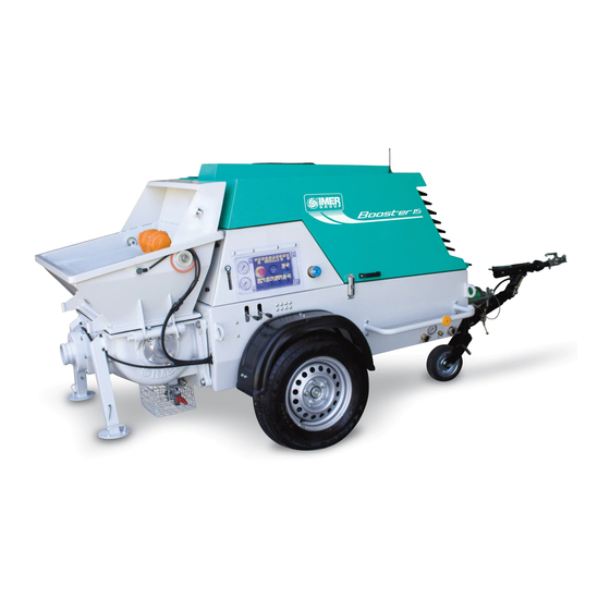
BOOSTER 15
(1106120-1106121-1106126)
POMPA PER CALCESTRUZZO
I
Manuale uso manutenzione e ricambi
POMPE À BÉTON
F
Manuel d'utilisation et d'entretien, pièces détachées
CONCRETE PUMP
GB
Operation, maintenance and spare parts manual
BETONPUMPE
D
Gebrauchs- und Wartungshandbuch
BOMBA PARA HORMIGÓN
E
Manual de uso, mantenimiento y recambios
3234441 R08 - 2019/01
IMER INTERNATIONAL S.p.A.
Via Salceto, 55 - 53036 POGGIBONSI (SI) -(ITALY)
Tel. 0577 97341 - Fax 0577 983304
www.imergroup.it
Advertisement

Subscribe to Our Youtube Channel
Related Manuals for IMER BOOSTER 15

Summary of Contents for IMER BOOSTER 15
- Page 1 BOOSTER 15 (1106120-1106121-1106126) POMPA PER CALCESTRUZZO Manuale uso manutenzione e ricambi POMPE À BÉTON Manuel d’utilisation et d’entretien, pièces détachées CONCRETE PUMP Operation, maintenance and spare parts manual BETONPUMPE Gebrauchs- und Wartungshandbuch BOMBA PARA HORMIGÓN Manual de uso, mantenimiento y recambios 3234441 R08 - 2019/01 IMER INTERNATIONAL S.p.A.
- Page 2 IMER INTERNATIONAL S.p.A. 13 16 ITALIANO FRANÇAIS ENGLISH DEUTSCH ESPAÑOL CANNE DI POMPAGGIO CONDUITES DE POMPAGE PUMPING PIPES PUMPROHRE TUBOS DE BOMBEO PISTONI PISTONS PISTONS KOLBEN PISTONES CILINDRI OLEODINAMICI CYLINDRES OLÉOHYDRAULIQUES HYDRAULIC CYLINDERS ÖLHYDRAULIKZYLINDER CILINDROS OLEODINÁMICOS VASCA LUBRIFICAZIONE CUVE DE LUBRIFICATION...
- Page 3 IMER INTERNATIONAL S.p.A. TABELLA - TABLEAU - TABLE - TABELLE - TABLA BOOSTER 15 DONNEES DATI TECNICI TECHNICAL DATA TECHNISCHE DATEN DATO TECNICOS TECHNIQUES CODICE MACCHINA CODE MACHINA MACHINE ODE MASCHINENCODE CODIGO DE LA MAQUINA 1106120-1106121 1106126 MOTORE DIESEL MOTEUR DIESEL...
- Page 4 Gentile Cliente, - LA POMPA PER CALCESTRUZZO è destinata per ci complimentiamo per il suo acquisto: la pompa per calcestruzzo IMER, l’impiego nei cantieri edili, per il pompaggio di calcestruzzo. Gli risultato di anni di esperienza, è una macchina di massima affidabilità e impasti devono essere pompabili: inerti in curva granulometri- dotata di soluzione tecniche innovative.
- Page 5 6. SICUREZZA ELETTRICA stabilizzatori, controllare la pressione di gonfiaggio dei pneumatici La pompa BOOSTER 15 ha un impianto elettrico in 12 Vcc. ed il funzionamento dei vari dispositivi luminosi, verificare che non siano appoggiati sulla macchina o all’interno della stessa elementi 7.
- Page 6 IMER INTERNATIONAL S.p.A. 9. INSTALLAZIONE La pompa deve essere piazzata in modo sicuro, su un piano orizzontale stabile, posizionando a terra i piedini di stazionamento (Fig.7 Rif.1) bloccando le ruote con cunei adeguati (Fig.7 Rif.2) e appoggiando a terra il supporto del ruotino (Fig.7 Rif.3). Per mag- giore sicurezza è...
- Page 7 - Utilizzare esclusivamente tubazioni e raccordi originali IMER. 11.1 COMANDO A DISTANZA DI SERIE L’utilizzo di tubazioni e raccordi non conformi alle specifiche IMER La macchina e’ dotata di un comando a distanza con cavo può compromettere il corretto funzionamento della macchina (Fig.14 Rif.1) che viene collegato alla presa (Fig.14 Rif.2) posta...
- Page 8 In caso di emergenza per arrestare la macchina premere il pulsan- - Controllare che lo carrozzeria sia chiusa a chiave. te rosso di emergenza (Fig.19 Rif.1). La BOOSTER 15 è dotata - Prima di mettere in marcia la macchina, assicurararsi che...
- Page 9 IMER INTERNATIONAL S.p.A. rifornimento per evitare le inutili perdite di tempo conseguenti allo spegnimento del motore per mancanza di carburante. Nel caso in cui durante il lavoro si verifichi un’anomalia al motore, all’impianto elettrico o oleodinamico che ne impediscano il prose-...
- Page 10 IMER INTERNATIONAL S.p.A. 15.PULIZIA E ARRESTO DELLA MACCHINA 16. PULIZIA DELLE TUBAZIONI La pulizia delle tubazioni puo’ essere realizzata in tre modi diversi: Dopo aver pompato l’ultima miscela, fermare l’agitatore con acqua a pressione,aria compressa o per aspirazione (solo con (Pag.2 Rif.8), il gruppo pompa (Pag.2 Rif.1) l’elettrovibratore della...
- Page 11 IMER INTERNATIONAL S.p.A. 16.3 PULIZIA PER ASPIRAZIONE Se il pompaggio e’ realizzato in verticale, si potra’ introdurre la spugna alla fine del tubo terminale, attivare l’aspirazione ruotando verso sinistra il selettore (Fig.19 Rif.7). Il cemento verra’ aspirato nella vasca. Avvertenze! Ogni metro di tubo D.50mm contiene approssimati-...
- Page 12 17.3 MANUTENZIONE SEMESTRALE Una volta ogni sei mesi far controllare la macchina presso un punto di assistenza autorizzato IMER. Fig.26.2 L’olio esausto è rifiuto speciale. Come tale va smaltito secondo i termini di legge.
- Page 13 IMER INTERNATIONAL S.p.A. Fig.27.1 Fig.28 20 REGISTRO VALVOLA AD “S” Il registro della valvola ad “S” va realizzato nel caso in cui la distan- za tra il disco (Fig.29 Rif.1) e la piastra antiusura (Fig.29 Rif.2) sia superiore a 0.25mm o nel caso di ripetute ostruzioni della valvola ad “S”.
- Page 14 NOTA: IMER INTERNATIONAL ha il diritto di modificare le caratteristiche della pompa e/o i contenuti del presente manuale, senza l’obbligo di ggiornare la macchina e/o i manuali precedenti.
- Page 15 IMER INTERNATIONAL S.p.A. INCONVENIENTI CAUSE RIMEDI - Controllare lo stato di carica della batteria e - Mancanza di alimentazione elettrica. del fusibile generale. Il pannello comandi non si accende - Terminare il pompaggio e contattare il - Avaria della scheda elettronica.
- Page 16 IMER INTERNATIONAL S.p.A.
- Page 17 IMER INTERNATIONAL S.p.A.
- Page 18 10 % 4-8 mm, 45 % 8-16 mm) et classe de consistance appropriée pompe à béton IMER est une machine extrêmement fiable, offrant des solutions (exemple : fluide, coulage (slump) 16-22 cm).
- Page 19 7. SÉCURITÉ MÉCANIQUE n’est posé sur la machine ou à l’intérieur ; vérifier que la machine Les points dangereux de la pompe IMER sont protégés par des est généralement en ordre. dispositifs de protection appropriés : ces derniers doivent être maintenus en conditions parfaites et montés ;...
- Page 20 IMER INTERNATIONAL S.p.A. 9. INSTALLATION La pompe doit être installée de manière sûre, sur un plan horizon- tal : faire arriver au sol les pieds de stationnement (Fig. 7 Rep. 1), bloquer les roues avec des cales appropriées (Fig. 7 Rep. 2), et appuyer au sol le support de la roue de manœuvre (Fig.
- Page 21 - Utiliser exclusivement des tuyaux et des raccords originaux 14 Rep. 1) à brancher sur la prise (Fig. 14 Rep. 2) située sur le IMER. L'utilisation de tuyaux et de raccords non conformes aux châssis de la machine. Lorsqu’on utilise la commande à distance, spécifications IMER peut compromettre le fonctionnement correct...
- Page 22 En cas d'urgence, appuyer sur le bouton d'arrêt d'urgence rouge - Avant de démarrer la machine, s’assurer que personne (si ce (Fig. 19, Rep. 1) pour arrêter la machine. La BOOSTER 15 est n’est les personnes autorisées) ne se trouve à une distance équipée également d’une manette d’accélération pour...
- Page 23 IMER INTERNATIONAL S.p.A. S’il se produit une défaillance du moteur, de l’installation électrique ou sur le circuit oléohydraulique au cours du travail et qu’on ne peut continuer, laver aussitôt la machine et les tuyauteries. À la fin, remonter le tout.
- Page 24 IMER INTERNATIONAL S.p.A. 15. NETTOYAGE ET ARRÊT DE LA MACHINE 16. NETTOYAGE DES TUYAUTERIES Les tuyauteries peuvent être nettoyées de trois manières : avec de Après avoir pompé le dernier béton, arrêter l’agitateur (Page l’eau sous pression, de l’air comprimé ou par aspiration (unique- 2 Rep.
- Page 25 IMER INTERNATIONAL S.p.A. Attention ! Chaque mètre de tuyau Ø 50 mm contient approximati- vement 2 l de matériau, tandis que chaque mètre de tuyau Ø 100 contient approximativement 8 l de matériau. Si le tuyau est très long, le béton pourrait déborder de la cuve.
- Page 26 IMER INTERNATIONAL S.p.A. - le manomètre pour le dispositif de nettoyage est efficace. Vérifier également que : - les tuyaux, les raccords et leurs joints et supports sont en bon état et parfaitement serrés ; - distributeur, électrovannes, manomètres, pressostats ne présen- tent pas de problèmes ;...
- Page 27 IMER INTERNATIONAL S.p.A. Fig. 27.1 Fig. 28 20 RÉGLAGE DE LA VANNE COUDÉE La vanne coudée doit être réglée si la distance entre le disque (Fig. 29 Rep. 1) et la plaque anti-usure (Fig. 29 Rep. 2) est supérieure à...
- Page 28 être effectués exclusivement par du personnel qualifié. Les pièces détachées à utiliser doivent être exclusivement des pièces d'origine IMER et elles ne peuvent pas être modi- fiées. Si des carters protecteurs sont déposés pour effectuer les réparations, ceux-ci devront être correctement remontés et fixés pour en vérifier leur efficacité...
- Page 29 IMER INTERNATIONAL S.p.A. INCONVÉNIENTS CAUSES REMÈDES - Contrôler l’état de charge de la batterie et le - Absence d’alimentation électrique. fusible général. Le panneau de contrôle ne s’allume pas - Finir le pompage et contacter le Centre - Défaillance de la carte électronique.
- Page 30 IMER INTERNATIONAL S.p.A.
- Page 31 IMER INTERNATIONAL S.p.A.
- Page 32 IMER INTERNATIONAL S.p.A. 4.1 DESCRIPTION OF CONCRETE PUMP (see fig. 1) Dear Customer, compliments on your purchase: the IMER concrete pump, resulting from The pump has the following major parts: years of research, offers maximum reliability and features innovative - A pumping unit composed of two concrete pumping pipes (Page 2 Ref.
- Page 33 The pump is not fitted with its own lighting and therefore the work- place must be sufficiently lit for this purpose. 6. ELECTRICAL SAFETY The BOOSTER 15 pump has a 12 V DC electrical circuit. 7. MECHANICAL SAFETY The hazardous parts of the IMER pump are protected by suitable Fig.
- Page 34 IMER INTERNATIONAL S.p.A. 9. INSTALLATION The pump must be securely located on a stable horizontal surface with its supporting feet (Fig. 7 Ref. 1) and the wheels chocked (Fig. 7 Ref. 2) with the jockey wheel support placed on the ground (Fig.
- Page 35 (Fig. 17 Ref. 3). 11.1 STANDARD REMOTE CONTROL - Only use original IMER pipes and fittings. The use of pipes and The machine is equipped with a cabled remote (Fig. 14 Ref. 1) fittings not complying with IMER specifications can compromise which connects to the socket (Fig.
- Page 36 In case of an emergency, press the red emergency button (Fig 19, cant tank may freeze and thus damage the sensor mount grill Ref. 1) to stop the machine. The BOOSTER 15 is also equipped and the sensors themselves. with throttle lever to adjust the Diesel engine speed from 2400 to 2700 RPM.
- Page 37 Use the lubricant available from IMER when replacing the pistons. Never use mineral oil or grease for fitting the pistons, as this may damage them. Avoid all types of benzene.
- Page 38 IMER INTERNATIONAL S.p.A. 15. MACHINE SHUTDOWN AND CLEANING - On the other hand, compressed water/compressed air cleaning allows all the concrete to be used and unloaded on site. After pumping the last mixture, stop the agitator (Page 2 Ref. 8), the pump unit (Page 2 Ref.
- Page 39 IMER INTERNATIONAL S.p.A. Warning! Every meter of D.50mm hose contains around 2 L of material, while every metre of D.100 hose contains around 8 L of material. If the hose is very long, the material may spill out of the tank.
- Page 40 17.3 SIX-MONTHLY MAINTENANCE Every six months arrange for an inspection of the machine by an authorised IMER service centre. Spent oil is a special waste. Therefore it must be dis- Fig. 26.2 posed of according to current legislation.
- Page 41 IMER INTERNATIONAL S.p.A. Fig. 27.1 Fig. 28 20 S VALVE REGISTRATION The S valve requires registration if the distance between the disc (Fig. 29 Ref. 1) and the wear plate (Fig. 29 Ref. 2) is greater than 0.25 mm or the S valve itself blocks repeatedly.
- Page 42 NOTE: IMER INTERNATIONAL reserves the right to modify the charac- teristics of the pump and/or the contents of this manual, without having to update the previous manuals and/or machine.
- Page 43 IMER INTERNATIONAL S.p.A. PROBLEM CAUSE CORRECTIVE ACTION - Check the battery charge and the master - No electric power supply. fuse. The control panel does not switch on - Stop pumping operations and contact the - Circuit board fault. authorised service centre...
- Page 44 IMER INTERNATIONAL S.p.A.
- Page 45 IMER INTERNATIONAL S.p.A.
- Page 46 Zuschlagstoffe innerhalb der Körnungskurve Sehr geehrte Kundin, sehr geehrter Kunde, wir beglückwünschen Sie zum Kauf der: Betonpumpe von IMER, dem (Beispiel: 45% 0-4mm, 10% 4-8mm, 45% 8-16mm) und passen- Ergebnis jahrelanger Erfahrung. Die Maschine zeichnet sich durch höchste der Konsistenzklasse (Beispiel: flüssig, Slump 16-22 cm).
- Page 47 (Abb.3 Pos.1). Die Stellfüße anheben und arretieren. 6. ELEKTRISCHE SICHERHEIT Den Reifenfülldruck und die Funktionstüchtigkeit der Beleuch- Die Pumpe BOOSTER 15 hat eine elektrische Anlage in 12 V DC. tungen prüfen und sicherstellen, dass auf oder in der Maschine keinerlei Materialien (Materialsäcke, Schläuche, Werkzeug usw.) 7.
- Page 48 IMER INTERNATIONAL S.p.A. 9. INSTALLATION Die Pumpe muss auf einer waagerechten, stabilen Fläche sicher aufgestellt werden. Die Stellfüße (Abb.7 Pos.1) müssen auf den Boden gestellt, und die Räder mit geeigneten Keilen blockiert werden (Abb.7 Pos.2). Der Ständer des Rädchens (Abb.7 Pos.3) muss ebenfalls auf dem Boden stehen.
- Page 49 Die Maschine ist mit einer Kabelfernbedienung (Abb.14 Pos.1) verwenden. Die Verwendung von Schläuchen und Anschlüssen ausgestattet, die an der Steckerbuchse (Abb.14 Pos.2) am in Abweichung von den IMER-Vorgaben kann den Maschinenbe- Chassis der Maschine angeschlossen wird. Bei Benutzung der trieb und die Sicherheit des Personals gefährden.
- Page 50 Um die Maschine im Notfall zum Stillstand zu bringen, den roten Not- - Sicherstellen, dass die Karosserie abgeschlossen ist. Aus-Taster (Abb. 8, Pos.1) drücken. Die Betonpumpe BOOSTER 15 - Bevor die Maschine in Bewegung gesetzt wird, muss si- ist auch mit einem Handgashebel ausgestattet, mit dem chergestellt werden, dass sich außer den befugten Personen...
- Page 51 An der leeren, sauberen Maschine mit abgestelltem Motor die Befestigungsschrauben der Verstrebungen lockern und den Trichter anheben. Beim Auswechseln der Kolben das bei IMER erhältliche Schmier- mittel benutzen. Für die Montage der Kolben auf keinen Fall Mineralfett oder -öl verwenden, da hierdurch die Kolben beschädigt werden könnten.
- Page 52 IMER INTERNATIONAL S.p.A. 15. AUSSCHALTEN UND REINIGUNG DER MASCHINE 16. REINIGUNG DER ROHRLEITUNGEN Für die Rohrleitungen gibt es drei Reinigungsverfahren: mit Druck- Nach Pumpen der letzten Mischung das Rührwerk (Seite 2 Pos.8), wasser, Druckluft oder durch Saugreinigung (nur bei Steigleitung).
- Page 53 IMER INTERNATIONAL S.p.A. 16.3 SAUGREINIGUNG Bei senkrechter Förderleitung kann der Reinigungsschwamm am Ende des Rohrendstücks eingeführt und durch Linksdrehung des Wahlschalters (Abb.19 Pos.7) die Absaugung aktiviert werden. Der Zement wird in das Becken gesaugt. Zur Beachtung! Jeder Rohrmeter D.50 mm fasst etwa 2 l Material, jeder Rohrmeter D.100 etwa 8 l Material.
- Page 54 (d.h. Ölwechsel, Austausch des Kraftstofffilters, Generatorrie- men) auch der Ölwechsel im Kompressor sowie der Austausch des Ölfilters der Hydraulikanlage auszuführen 17.3 HALBJÄHRLICHE WARTUNG Die Maschine alle sechs Monate bei einer autorisierten IMER- Kundendienststelle kontrollieren lassen. Abb.26.2 Altöl muss als Sondermüll vorschriftsmäßig entsorgt werden.
- Page 55 IMER INTERNATIONAL S.p.A. Abb.27.1 Abb.28 20 EINSTELLUNG DER “S”-ROHRWEICHE Die Einstellung der “S”-Rohrweiche ist erforderlich, wenn der Abstand zwischen der Scheibe (Abb.29 Pos.1) und der Verschleißplatte (Abb.29 Pos.2) größer als 0,25mm ist, oder bei wiederholter Verstop- fung der “S”-Rohrweiche. Eine nicht einwandfreie Einstellung der “S”-Rohrweiche führt zu Druck- abfall, daher ist die geförderte Materialmenge während der Pumppha-...
- Page 56 Auslösung der Sicherheitsvorkehrungen geprüft werden. HINWEIS: IMER INTERNATIONAL behält sich das Recht vor, die Eigen- schaften der Pumpe und/oder den Inhalt des vorliegenden Handbuchs zu ändern, ohne vorhergehende Maschinen und/oder Handbücher zu aktualisieren.
- Page 57 IMER INTERNATIONAL S.p.A. STÖRUNGEN URSACHEN ABHILFE - Ladezustand der Batterie und Zustand der - Keine Stromversorgung. Hauptsicherung kontrollieren. Das Bedienfeld schaltet nicht ein - Pumpvorgang beenden und eine autorisierte - Defekt der Elektronikplatine. Kundendienststelle zu Rate ziehen - Ladezustand der Batterie sowie Zustand...
- Page 58 IMER INTERNATIONAL S.p.A.
- Page 59 IMER INTERNATIONAL S.p.A.
- Page 60 Las mezclas Apreciado Cliente: Enhorabuena por su compra. La bomba para hormigón IMER es el resul- han de poderse bombear: áridos con curva granulométri- tado de años de experiencia y presenta soluciones técnicas innovadoras que...
- Page 61 6. SEGURIDAD ELÉCTRICA último, compruebe que, en general, todo esté bien y que no se ha- La bomba BOOSTER 15 posee un sistema eléctrico de 12 Vcc. yan quedado componentes u objetos (bolsas de material, tubos, herramientas, etc.) sobre la máquina o en su interior.
- Page 62 IMER INTERNATIONAL S.p.A. 9. INSTALACIÓN Instale la bomba sobre una superficie horizontal y perfectamente estable, de manera que quede en una posición segura; para ello, apoye las patas (fig. 7, ref. 1) y el soporte del tiro (fig. 7, ref. 3) al suelo y bloquee las ruedas (fig.
- Page 63 Spritz Beton, bomba de acelerador de fraguado e hidrolim- 17, ref. 3) de la pistola. piadora de alta presión. - Utilice sólo tubos y racores originales IMER. El uso de tubos 11.1 MANDO A DISTANCIA DE SERIE y racores no conformes a las especificaciones de IMER puede La máquina posee un mando a distancia con cable (fig.
- Page 64 IMER INTERNATIONAL S.p.A. 12. CONTROLES PRELIMINARES La máquina puede equiparse con una bomba de acelerador de Antes de empezar a trabajar, controle los siguientes niveles: aceite fraguado, que puede funcionar en modo manual o automático. Para del motor, refrigerante del radiador, aceite del circuito oleodinámico y habilitar el funcionamiento manual, gire el selector (fig.
- Page 65 IMER INTERNATIONAL S.p.A. motor, el sistema eléctrico o el oleodinámico que impida seguir trabajando, lave inmediatamente la máquina y los tubos. Luego, vuelva a montar todas las piezas. TESTIGO PARPADEANTE TESTIGO ENCENDIDO CON LUZ FIJA Fig. 21 14 MODALIDAD DE USO La rejilla de seguridad de la tolva siempre tiene que estar instalada y correctamente fijada.
- Page 66 IMER INTERNATIONAL S.p.A. 15. LIMPIEZA Y PARO DE LA MÁQUINA En concreto: - con la limpieza por aspiración, el material de los tubos se envía Tras bombear la última mezcla, pare el agitador (pág. 2, ref. 8), el al depósito; téngase en cuenta que el depósito permite recuperar grupo bomba (pág.
- Page 67 IMER INTERNATIONAL S.p.A. ¡Advertencia! En cada metro de tubo de 50 mm de diámetro hay unos 2 litros de material; en cada metro de 100 mm, unos 8 litros. Si el tubo es muy largo, es posible que el cemento del depó- sito se derrame.
- Page 68 17.3 MANTENIMIENTO SEMESTRAL Cada seis meses, haga controlar la máquina por un Centro de Asistencia autorizado de IMER. Fig. 26.2 El aceite usado es un residuo especial. Por lo tanto, debe eliminarlo según la legislación vigente.
- Page 69 IMER INTERNATIONAL S.p.A. Fig. 27.1 Fig. 28 20 REGULACIÓN DE LA VÁLVULA EN “S” La válvula en “S” se ha de regular si la distancia entre el disco (fig. 29, ref. 1) y la placa antidesgaste (fig. 29, ref. 2) es superior a 0,25 mm o si dicha válvula se atasca a menudo.
- Page 70 NOTA: IMER INTERNATIONAL se reserva el derecho de modificar las características de la bomba o los contenidos del manual sin obli- gación de actualizar las máquinas o manuales precedentes.
- Page 71 IMER INTERNATIONAL S.p.A. INCONVENIENTES CAUSAS SOLUCIONES - Controle la carga de la batería y el fusible - Falta alimentación eléctrica. general. El panel de mandos no se enciende. - Termine el bombeo y póngase en contacto con - Avería de la tarjeta electrónica.
- Page 72 IMER INTERNATIONAL S.p.A.
- Page 73 IMER INTERNATIONAL S.p.A. RICAMBI PIÈCES DÉTACHÉES SPARE PARTS ERSATZTEILE REPUESTOS...
- Page 74 IMER INTERNATIONAL S.p.A. TAV.1 TAV.1 ASSALE - ESSIEU - AXLE - ACHSE - EJE Rif. Cod. NOTE 3233423 ASSALE STRADALE ESSIEU À LA ROUTIER AXLE TO ROAD ACHSE STRAßENVER- EJE DE LA CARRE- KEHR TERA 3236573 ASSALE NON STRA- ESSIEU PAS À LA...
- Page 75 IMER INTERNATIONAL S.p.A.
- Page 76 IMER INTERNATIONAL S.p.A. TAV.3...
- Page 77 IMER INTERNATIONAL S.p.A. TAV. 3 RIF. COD. NOTE 3227509 TELAIO CHÂSSIS FRAME RAHMEN BASTIDOR 2224430 RONDELLA RONDELLE WASHER UNTERLEGSCHEIBE ARANDELA 3224780 STAFFA MANOMETRO ÉTRIER DE FIXATION MANOMÈTRE HANGER BÜGEL CORCHETE 2223921 DADO ÉCROU MUTTER TUERCA 3228922 DISTANZIALE ENTRETOISE SPACER ABSTANDHALTER...
- Page 78 IMER INTERNATIONAL S.p.A. TAV.4...
- Page 79 IMER INTERNATIONAL S.p.A. TAV.4 From S/N Rif. Cod. NOTE BOMBA DE ENGRA- 3229033 POMPA A INGRANAGGI POMPE À ENGRENAGE GEAR PUMP ZAHNRADPUMPE NAJES 3234276 PARATIA RADIATORE BOO- CLOISON RADIATOR MAMPARO KUHLERSCHOTT STER 15 YANMAR RADIATEUR BULKHEAD RADIATOR 3227625 MARMITTA SILENCER...
- Page 80 IMER INTERNATIONAL S.p.A. TAV.5...
- Page 81 IMER INTERNATIONAL S.p.A. TAV. 5 DA MATRICOLA: FROM SERIAL NUMBER: À PARTIR DU NUMÉRO DE ÉRIE: VON SERIENNUMMER: À PARTIR DU NUMÉRO RIF. COD. NOTE DE ÉRIE: 3227248 TRAMOGGIA TRÉMIE HOPPER TRICHTER TOLVA CHROME TAMBOR 3227583 CANNA CROMATA BARILLET CHROMÉ...
- Page 82 IMER INTERNATIONAL S.p.A. TAV.6 TAV.6 Rif. Cod. NOTE 3227571 TRAMOGGIA TRÉMIE HOPPER TRICHTER TOLVA 3227605 PERNO GRIGLIA AXE DE GRILLE MESH PIN NETZBOLZEN PERNO RED 3228924 ANTIVIBRANTE ANTIVIBRATILES VIBRATION DAMPER SCHWINGUNGS ANTIVIBRADORES 50X20 3227608 GUARNIZIONE JOINT SEAL DICHTUNG JUNTA 3227630...
- Page 83 IMER INTERNATIONAL S.p.A.
- Page 84 IMER INTERNATIONAL S.p.A. SCHEMA IDRAULICO-HYDRAULIC SCHEME- HYDRAULIKSCHEMA-ESQUEMA HIDR ÁULICO...
- Page 85 IMER INTERNATIONAL S.p.A. SCHÉMA HYDRAULIQUE...
- Page 86 IMER INTERNATIONAL S.p.A. SCHEMA COLLEGAMENTO PANNELLO DI COMANDO ELECTRIC CONNECTION CONTROL PANEL ELEKTROANSCHLUSS BEDIENFELD CONEXIÓN ELÉCTRICA DEL PANEL DE CONTROL...
- Page 87 IMER INTERNATIONAL S.p.A. PANNEAU DE COMMANDE ELECTRIQUE DE CONNEXION...
- Page 88 IMER INTERNATIONAL S.p.A. SCHEMA CENTRALINA ELETTRONICA MOTORE YANMAR SCHEMA DE UNITE’ ELECTRONIQUE DE MOTEUR YANMAR...
- Page 89 IMER INTERNATIONAL S.p.A.
- Page 90 IMER INTERNATIONAL S.p.A. (14) URGENCE (13) (20) COMPTEUR D'HEURES (11) ANZE GENERALI (18) VIBRATEUR 2768 - mK ELECTRIQUE (15) COMMANDE A DISTANCE DEBIT (12) ROTATION (19) (10) DEMARRAGE DE MOTEUR (17) (16)
- Page 91 IMER INTERNATIONAL S.p.A. MANUTENZIONI PROGRAMMATE...
- Page 92 IMER INTERNATIONAL S.p.A. SCHEDULED MAINTENANCE -...
- Page 93 IMER INTERNATIONAL S.p.A.
- Page 94 IMER INTERNATIONAL S.p.A. REGISTRO DI MACCHINA, COLLAUDI, MANUTENZIONE - REGISTRE MACHINE, ESSAIS ET ENTRETIEN - MACHINE REGISTER ,TESTS AND MAINTENANCE - MASCHINENREGISTER, ABNAHMEN UND WARTUNG - RISULTATI, ANNOTAZIONI E FIRMA DEL COMPILATORE RÉSULTATS, ANNOTATIONS ET SIGNATURE DU LUOGO D’INSTALLAZIONE VERIFICA PARTI DELLA MACCHINA PRÉPOSÉ...
- Page 95 IMER INTERNATIONAL S.p.A. REGISTRO DI MACCHINA, COLLAUDI, MANUTENZIONE - REGISTRE MACHINE, ESSAIS ET ENTRETIEN - MACHINE REGISTER ,TESTS AND MAINTENANCE - MASCHINENREGISTER, ABNAHMEN UND WARTUNG - RISULTATI, ANNOTAZIONI E FIRMA DEL COMPILATORE RÉSULTATS, ANNOTATIONS ET SIGNATURE DU LUOGO D’INSTALLAZIONE VERIFICA PARTI DELLA MACCHINA PRÉPOSÉ...
- Page 96 Pour tous les matériels produits par Imer International spa la durée de la garantie est de 1 (un ) an à partir de la date de livraison au client final sans toutefois dépasser le délai des 30 (trente) mois à partir de la date de livraison initiale de IMER. Le réparations effectuées pendant la période de garantie n’interrompent pas la période de garantie général.
- Page 97 Para todos los productos de Imer International s.p.a la garantía es de 1 (uno) año a partir de la fecha de entrega al usuario y no más tarde de 30 (treinta) meses a partir de la fecha de envío de IMER. Todas la reparaciones efectuadas en el período de garantía no interrumpen la garantía misma.
- Page 98 (Annex 1 Paragraph 13 Directive 2000/14/EC) BETONPUMPE : BOOSTER 15 kW 22.3 (Anhang 1 Absatz 13 der Richtlinie 2000/14/EG) BOOSTER 15 “USA” kW 17.8 BOMBA PARA HORMIGÓN : (Annexo 1 Párrafo 13 la Directiva 2000/14/CE) Matricola N°: Numero de serie:...
Need help?
Do you have a question about the BOOSTER 15 and is the answer not in the manual?
Questions and answers