Table of Contents
Advertisement
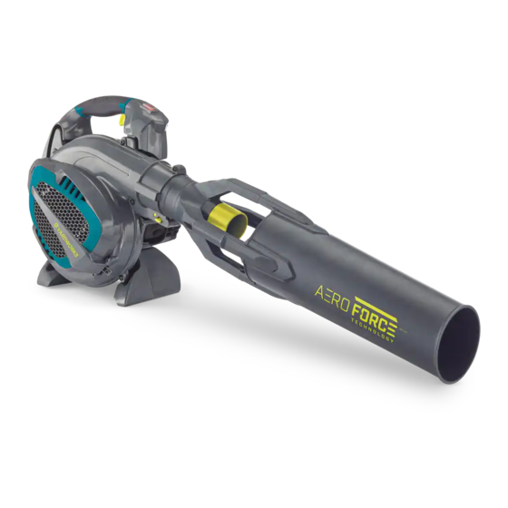
Leaf Blower & Vacuum
model number 060-2385-8 | contact us: 1.866.523.5218
WARNING: To reduce the risk of injury, the user must read and understand the operator's manual
before using this product. If you do not understand the warnings and instructions in the operator's
manual, do not use this product.
NOTICE: Do not use E15 or E85 fuel (or fuel containing greater than 10% ethanol) in this product.
It is a violation of federal law and will damage the unit and void your warranty. FUEL MIXTURE for this
product is powered by a 2-cycle engine and requires pre-mixing gasoline and 2-cycle oil in a 40:1 ratio.
Pre-mix unleaded gasoline and 2-cycle engine oil in a clean container approved for gasoline. DO NOT
mix quantities larger than usable in a 30-day period.
READ AND SAVE THIS MANUAL. This manual contains important safety precautions which should be
read and understood before operating the product. Failure to do so could result in serious injury. This
manual should remain with the product. Specifications, descriptions and illustrations in this manual are
as accurate as known at the time of publication, but are subject to change without notice.
Advertisement
Table of Contents

Related Manuals for Yardworks 060-2385-8


Summary of Contents for Yardworks 060-2385-8
- Page 1 Leaf Blower & Vacuum model number 060-2385-8 | contact us: 1.866.523.5218 WARNING: To reduce the risk of injury, the user must read and understand the operator’s manual before using this product. If you do not understand the warnings and instructions in the operator’s manual, do not use this product.
- Page 2 | contact us: 1.866.523.5218 060-2385-8 SAFETY INSTRUCTIONS SAFETY SYMBOLS OPERATION SYMBOLS SPECIFICATIONS SAFETY LABELS CONTROLS AND FEATURES ASSEMBLY OPERATION MAINTENANCE TROUBLESHOOTING EXPLODED VIEW - A (PRODUCT) PARTS LIST – A (PRODUCT) EXPLODED VIEW - B (PRODUCT) PARTS LIST – B (PRODUCT) EXPLODED VIEW - C (PRODUCT) PARTS LIST –...
-
Page 3: Safety Definitions
| contact us: 1.866.523.5218 060-2385-8 SAFETY DEFINITIONS Failure to do so could result in objects being thrown into your eyes and other The purpose of safety symbols is to attract possible serious injuries. your attention to possible dangers. The... - Page 4 | contact us: 1.866.523.5218 060-2385-8 Use only identical manufacturer’s Do not operate vacuum without – – replacement parts and accessories. vacuum bag installed; flying debris Use of any other parts may create a could cause serious injury. Always hazard or cause product damage.
-
Page 5: Fuel Safety
| contact us: 1.866.523.5218 060-2385-8 To reduce the risk of injury associated FUEL SAFETY – with contacting rotating parts, stop the Fuel is highly flammable. Take – engine before installing or removing precautions when using to reduce the attachments. - Page 6 | contact us: 1.866.523.5218 060-2385-8 If fuel is spilled, do not attempt to start – the engine but move the machine away from the area of spillage and avoid creating any source of ignition until fuel vapours have dissipated.
- Page 7 | contact us: 1.866.523.5218 060-2385-8 Some of the following symbols may be used on this product. Please study them and learn their meaning. Proper interpretation of these symbols will allow you to more safely operate the product. SYMBOL MEANING Read Operator’s Manual.
- Page 8 | contact us: 1.866.523.5218 060-2385-8 SYMBOL MEANING Thrown Objects. This machine may pick up and throw objects which can cause serious personal injury. Clearance. Keep all objects including others at least 50' (15m) from this machine. Only one person should operate the product.
- Page 9 | contact us: 1.866.523.5218 060-2385-8 Some of the following symbols may be used on this product. Please study them and learn their meaning. Proper interpretation of these symbols will allow you to more safely operate the product. SYMBOL MEANING Cold Prime.
- Page 10 | contact us: 1.866.523.5218 060-2385-8 SYMBOL MEANING DO NOT USE E85. Use regular unleaded gasoline with a minimum octane rating of 87 and an ethanol content of less than 10% by volume. USE LESS THAN 10% ETHANOL. Use regular unleaded gasoline with a minimum octane rating of 87 and an ethanol content of less than 10% by volume.
-
Page 11: Fuel Mixture
| contact us: 1.866.523.5218 060-2385-8 BLOWER/VAC SPECIFICATIONS Displacement 27.6 cc Type 2-Stroke Max 85 MPH (137 km/h) Air Velocity* Max 700 CFM (ft /min) Impeller Type 6 1/2" (16.8 cm) plastic Mulching Blade 3" (7.6 cm) metal Sound Pressure* 79 dB(A) @ 50' (15.2 m) - Page 12 | contact us: 1.866.523.5218 060-2385-8 These labels warn you of potential hazards that can cause serious injury. Read them carefully. If a label comes off or becomes hard to read, contact Technical Support Team for possible replacement. LABEL...
- Page 13 | contact us: 1.866.523.5218 060-2385-8 LABEL DESCRIPTION DO NOT TOUCH! WARNING Hot surface. Hot Surface Operation of this equipment may create sparks that can start fires around dry vegetation. A spark arrestor may be required. The operator should contact local fire agencies for laws or regulations relating to fire prevention requirements.
- Page 14 | contact us: 1.866.523.5218 060-2385-8 BLOWER VACUUM A. Lower blower tube L. Upper vacuum tube B. Upper blower tube M. Tube lock C. Muffler N. Lower vacuum tube D. Vacuum handle O. Vacuum bag E. Fuel cap P. Vacuum bag exit F.
-
Page 15: Tools Included
| contact us: 1.866.523.5218 060-2385-8 TOOLS INCLUDED Spark plug wrench – Reversible flathead and cross-head – screwdriver T25 double-ended wrench – PACKING LIST Blower Vacuum bag – – Upper and lower Aeroforce™ blower Vacuum bag adaptor – –... - Page 16 | contact us: 1.866.523.5218 060-2385-8 BLOWER Attaching the Aeroforce™ Blower Tube 1. Align the upper and lower blower tubes at the arrows. Once confirmed all 4 arms fit flush together, press the two parts together. 2. Insert screws and tighten completely on all 4 sides.
- Page 17 | contact us: 1.866.523.5218 060-2385-8 VACUUM Removing the Blower Tube 1. Press the tab to release the blower 2. Slightly twist the blower tube until it releases from the blower outlet. 3. Remove the blower tube from the blower outlet.
- Page 18 | contact us: 1.866.523.5218 060-2385-8 5. Insert the end of the vacuum bag adaptor in the bag opening and close the inlet with the hook and loop fastener provided. 6. Secure the upper and lower vacuum tubes together by aligning the arrows.
- Page 19 | contact us: 1.866.523.5218 060-2385-8 10. While holding the impeller door open, align the slots on the vacuum tube with the tabs in the impeller intake. 11. Insert the upper vacuum tube into the impeller intake. 12. Twist the upper vacuum tube counter-clockwise with both hands until it locks into place.
-
Page 20: Fueling And Refueling
| contact us: 1.866.523.5218 060-2385-8 APPLICATIONS Clearing leaves and other debris from your lawn. – Keeping decks and driveways free from leaves and other forms of debris. – Vacuuming leaves from your lawn. – FUELING AND REFUELING Fuel Mixture This product is powered by a 2-cycle engine and requires pre-mixing gasoline and 2-cycle oil in a 40:1 ratio. - Page 21 | contact us: 1.866.523.5218 060-2385-8 Filling the Tank 1. Place the blower/vacuum on a flat stable surface, with the fuel tank cap facing upwards. 2. Clean the surface around the fuel cap to prevent contamination. 3. Loosen the fuel cap slowly by turning counter-clockwise.
-
Page 22: Starting And Stopping
| contact us: 1.866.523.5218 060-2385-8 STARTING AND STOPPING To Start A Cold Engine: 1. Blower should be on a flat, bare surface for starting. 2. Set the choke knob (C) to the CHOKE position. 3. Slowly press the primer bulb (D) 7-10 times. - Page 23 | contact us: 1.866.523.5218 060-2385-8 To Start A Warm Or Hot Engine: 1. Set the choke knob (C) to the RUN position. 2. Slowly press the primer bulb (D) 4-6 times. 3. Pull the starter grip (A) until the engine runs.
-
Page 24: Proper Blower Operation
| contact us: 1.866.523.5218 060-2385-8 PROPER BLOWER OPERATION Safety: Fully familiarize yourself with the IMPORTANT SAFETY INSTRUCTIONS section. – To keep from scattering debris, blow around the outer edges of a debris pile. Never – blow directly into the centre of a pile. -
Page 25: General Tips
| contact us: 1.866.523.5218 060-2385-8 GENERAL TIPS: To reduce sound levels, limit the number of pieces of equipment used at any one time. – Use rakes and brooms to loosen debris before blowing. – In dusty conditions, slightly dampen surfaces when water is available. - Page 26 | contact us: 1.866.523.5218 060-2385-8 PROPER VACUUM OPERATION Safety: Fully familiarize yourself with the IMPORTANT SAFETY INSTRUCTIONS section. – To keep from scattering debris, blow around the outer edges of a debris pile. Never – blow directly into the center of a pile.
-
Page 27: Throttle Lock
| contact us: 1.866.523.5218 060-2385-8 Always point vacuum tube downhill when working on a hillside. – To avoid serious injury to the operator or damage to the unit, do not pick up rocks, – metal, broken glass, bottles, or other similar objects. -
Page 28: General Maintenance
| contact us: 1.866.523.5218 060-2385-8 GENERAL MAINTENANCE Avoid using solvents when cleaning plastic parts. Most plastics are susceptible to damage from various types of commercial solvents and may be damaged by their use. Use clean cloths to remove dirt, dust, lubricant, grease, etc. -
Page 29: Cleaning The Air Filter
| contact us: 1.866.523.5218 060-2385-8 CLEANING THE AIR FILTER For proper performance and long life, keep air filter clean. Remove the air filter cover by turning the dial counter-clockwise while gently pulling on – the cover. Rinse filter with clean water. -
Page 30: Cleaning The Exhaust Port, Muffler And Spark Arrestor
| contact us: 1.866.523.5218 060-2385-8 CLEANING THE EXHAUST PORT, MUFFLER AND SPARK ARRESTOR (IF APPLICABLE) The spark arrestor must be cleaned or replaced every 50 hours or yearly to ensure – proper performance of your product. Spark arrestors may be in different locations depending on the model purchased. -
Page 31: Spark Plug Replacement
| contact us: 1.866.523.5218 060-2385-8 FUEL CAP WARNING: Check for fuel leaks. A leaking fuel cap is a fire hazard and must be replaced immediately. If you find any leaks, correct the problem before using the product. Failure to do so could result in a fire that could cause serious personal injury. -
Page 32: Maintenance Schedule
| contact us: 1.866.523.5218 060-2385-8 MAINTENANCE SCHEDULE Follow the service intervals indicated in the schedule below. Service your blower/vacuum more frequently when operating in adverse conditions. Contact our help line authorized service dealer. Time intervals shown are maximum. Actual use and your experience will determine the frequency of required maintenance. - Page 33 | contact us: 1.866.523.5218 060-2385-8 PROBLEM CHECK CAUSE SOLUTION Drain and fill with correct Fuel tank Incorrect fuel fuel Fuel filter Fuel filter is clogged Replace fuel filter Let unit sit to air out (15 minutes) or remove...
- Page 34 | contact us: 1.866.523.5218 060-2385-8...
- Page 35 | contact us: 1.866.523.5218 060-2385-8 Item Description Drawing QTY. Fore Air Tube Assembly F28.0414.0000 Fore Air Tube F28.0414.0001 Bushing F28.0414.0003 Screw ST4.9 x 115 F28.0414.0005 Sleeve F28.0414.0004 Rear Air Tube F28.0414.0002 Aspiration Channel 2 F28.0115.0002 Aspiration Channel 1 F28.0115.0001...
- Page 36 | contact us: 1.866.523.5218 060-2385-8...
- Page 37 | contact us: 1.866.523.5218 060-2385-8 Item Description Drawing QTY. Upper Cover, Under Handle F28.0112.0300 Screw ST5 x 19 01.01.3202 Screw ST5 x 16 01.01.3031 Under Handle F28.0112.0003 Under Handle Support F28.0112.0004 Under Cover, Under Handle F28.0112.0400 Left Cover, Upper Handle F28.0112.0100...
- Page 38 | contact us: 1.866.523.5218 060-2385-8 Item Description Drawing QTY. Button Spring SBC653KD.02.01-06 Fixed Rod F28.0211.0006 Screw M5 x 25 01.01.6203 Plate Washer F28.0111.0010 Strip Seal 3 x 3 x 770 F28.0111.0013 Impeller F28.0111.0009 Blade F28.0111.0011 Left Handed Nut M8 01.03.0284...
- Page 39 | contact us: 1.866.523.5218 060-2385-8 This page intentionally left blank...
- Page 40 | contact us: 1.866.523.5218 060-2385-8...
- Page 41 | contact us: 1.866.523.5218 060-2385-8 Item Description Drawing QTY. Starter Assembly F28.0210.0000 Start Housing Decorative Board F28.0210.0001 Screw M5 x 20 01.01.6201 Start Housing F28.0210.0100 Eyelet YD25.02.01-2 Start Rope YD25.02.00-5 Start Grip YD62.02.00-3 Coil Spring YD42.06-6 Coil Spring Cover YD42.06-7...
- Page 42 | contact us: 1.866.523.5218 060-2385-8 Item Description Drawing QTY. Engine Block F28.0201.0000 Inlet Pipe Sealing Gasket F28.0101.0001 Admitting Pipe F28.0101.0100 Screw M5 x 25 01.01.6203 Carburetor Gasket TBC261D.01.00.00-4 Carburetor F28.0101.0200 Choke Knob F28.0100.0001 Air Cleaner Base F28.0104.0003 Screw M5 x 45 01.01.6249...
-
Page 43: Year Limited Warranty
060-2385-8 2-YEAR LIMITED WARRANTY For TWO YEARS from the date of purchase within Canada, YARDWORKS CANADA will, at its option, repair or replace for the original purchaser, free of charge, any part or parts found to be defective in material or workmanship. -
Page 44: Your Warranty Rights And Obligations
CHAMPION POWER EQUIPMENT, INC. (CPE), THE UNITED STATES ENVIRONMENTAL PROTECTION AGENCY (U.S. EPA) EMISSION CONTROL SYSTEM WARRANTY Your Champion Power Equipment (CPE) engine complies with U.S. EPA emission regulations. YOUR WARRANTY RIGHTS AND OBLIGATIONS: The US EPA, and CPE are pleased to explain the Federal Emission Control Systems Warranty on your 2020 small off- road engine (SORE) and engine powered equipment. -
Page 45: Emission Control System Warranty
EMISSION CONTROL SYSTEM WARRANTY The following are specific provisions relative to your Emission Control System (ECS) Warranty Coverage. APPLICABILITY: This warranty shall apply to 1997 and later model year small off-road engines. The ECS Warranty Period shall begin on the date the new engine is delivered to its original, end-use purchaser and shall continue for 24 consecutive months thereafter. -
Page 46: To Obtain Warranty Service
EMISSION-RELATED PARTS INCLUDE THE FOLLOWING: (using those portions of the list applicable to the engine) Systems covered by this warranty Parts Description Fuel Metering System Fuel regulator, carburetor and internal parts Air Induction System Air cleaner, intake manifold Ignition System Spark plug and parts, magneto ignition system Exhaust System Exhaust manifold, catalytic converter...
Need help?
Do you have a question about the 060-2385-8 and is the answer not in the manual?
Questions and answers