Table of Contents
Advertisement
Quick Links
Copyright
All rights are reserved. No part of this publication may be reproduced, transmitted,
transcribed, stored in a retrieval system or translated into any language or computer
language, in any form or by any means, electronic, mechanical, magnetic, optical,
chemical, manual or otherwise, without the prior written permission of the company.
Brands and product names are trademarks or registered trademarks of their respective
companies.
The vendor makes no representations or warranties with respect to the contents herein
and especially disclaim any implied warranties of merchantability or fitness for any
purpose. Further the vendor reserves the right to revise this publication and to make
changes to the contents herein without obligation to notify any party beforehand.
Duplication of this publication, in part or in whole, is not allowed without first obtaining
the vendor's approval in writing.
Trademark
All the trademarks or brands in this document are registered by their respective owner.
Disclaimer
We make no warranty of any kind with regard to the content of this user's manual. The
content is subject to change without notice and we will not be responsible for any
mistakes found in this user's manual. All the brand and product names are trademarks of
their respective companies.
FCC Compliance Statement
This equipment has been tested and found to comply with the limits of a Class B digital
device, pursuant to Part 15 of the FCC Rules. These limits are designed to provide
reasonable protection against harmful interference in a residential installation. This
equipment generates, uses and can radiate radio frequency energy and, if not installed
and used in accordance with the instructions, may cause harmful interference to radio
communications. Operation of this equipment in a residential area is likely to cause
harmful interference in which case the user will be required to correct the interference at
his own expense. However, there is no guarantee that interference will not occur in a
particular installation.
CE Mark
The device is in accordance with 89/336 ECC-ENC Directive.
Ver: EG101
PX915P-2V
Advertisement
Table of Contents

Subscribe to Our Youtube Channel
Related Manuals for Albatron PX915P-2V


Summary of Contents for Albatron PX915P-2V
- Page 1 PX915P-2V Copyright All rights are reserved. No part of this publication may be reproduced, transmitted, transcribed, stored in a retrieval system or translated into any language or computer language, in any form or by any means, electronic, mechanical, magnetic, optical, chemical, manual or otherwise, without the prior written permission of the company.
- Page 2 PX915P-2V ® Intel 915P & ICH6 Support Socket 775 ® ® Intel Pentium 4 Prescott Processor User Manual Enabling the Hyper-Threading Technology, your computer system is required to have components as the following: CPU: An Intel ® Pentium ® 4 Processor with HT Technology Chipset: An Intel ®...
- Page 3 Do not touch any IC chip, lead, connector or other components. Always unplug the AC power when you install or remove any device on the mainboard or when confuguring pins and switches. Packing List PX915P-2V Mainboard IDE Cable FDD Cable SATA Cable...
-
Page 4: Table Of Contents
Table of Contents CHAPTER 1. GETTING STARTED .............1 ....................... 1 NTRODUCTION ....................... 2 PECIFICATION ....................5 ONFIGURATION Layout of PX915P-2V ..................5 ................... 6 ARDWARE NSTALLATION CPU Processor Installation................6 Memory Installation ..................7 Back Panel Configuration................9 Connectors..................... 11 Front Panel Headers.................. -
Page 5: Chapter 1. Getting Started
There are maximal eight USB2.0/ 1.1 ports can be set on this mainboard. The PX915P-2V also comes with an onboard 10/100 Mbps Ethernet LAN chip (1GBLAN is optional). There is a LAN port on the case back panel that you can directly plug into an Internet cable. -
Page 6: Specification
Mainboard PX915P-2V Specification CPU: Support Socket 775 Pentium ® 4 Prescott Processor Support Hyper-Threading Technology Support FSB (Front Side Bus) 800 MHz Chipset: Northbridge Chipset – Intel® 915P Southbridge Chipset – Intel® ICH6 I/O Controller – Winbond® W83627THF AC’ 97 Sound Codec – Realtek® ALC655 Mb LAN Controller –... - Page 7 Mainboard PX915P-2V IDE Connector: One IDE connectors, support up to four IDE devices Supports Ultra ATA 33/ 66/100/133 Supports high capacity hard disk drives Serial ATA Connector: Four SATA connectors, support up to four SATA HDDs can be set up Supports SATA 1.0 specification and with 150MBps transmission speeds...
- Page 8 This function is used for detecting the system hangs during the POST stage due to conflicts resulting from changing the system BIOS settings. Once the problem is detected, the system will reset the configurations and reboot the system within five seconds. ABS (Albatron BIOS Security): Supports ABS card (optional) Supports BIOS backup...
-
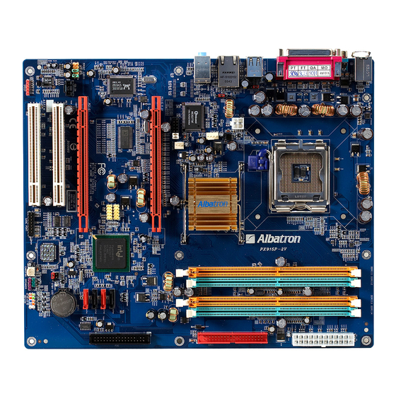
Page 9: Configuration
Mainboard PX915P-2V Configuration Layout of PX915P-2V... -
Page 10: Hardware Installation
Mainboard PX915P-2V Hardware Installation This section will assist you in quickly installing your system hardware. Wear a wrist ground strap before handling components. Electrostatic discharge may damage the system’s components. CPU Processor Installation This mainboard supports Intel ® Pentium ®... -
Page 11: Memory Installation
“ground” and should be attached to pin-1 of the header. Memory Installation: DIMM1/2 The PX915P-2V provides four DIMM (Dual In-Line Memory Modules) sockets which allowing you to install 240-pin, unbuffered non-ECC, DDRII 400/ DDRII 533 SDRAMs. It also supports Dual Channel Technology and allows you installing a total memory capacity of 4 GB. - Page 12 Mainboard PX915P-2V How to enable Dual-Channel DDRII: 1. This mainboard provides Dual-Channel functionality for the four DIMM sockets. Enabling Dual-Channel can significantly increase your data access rates. DIMM1 and DIMM2 share one channel, and DIMM3 and DIMM4 share another channel.
-
Page 13: Back Panel Configuration
Mainboard PX915P-2V Back Panel Configuration PS/2 Mouse & PS/2 Keyboard Ports: KB/MS This mainboard provides a standard PS/2 mouse port and a PS/2 keyboard port. The pin assignments are described below. PS/2 Mouse Assignment Assignment Data +5 V (fused) No connect... - Page 14 Mainboard PX915P-2V USB Ports/LAN Port: USB/ GBLAN, USB/LAN(GBLAN is optional) There are four onboard USB 2.0/ 1.1 ports on the back panel. These USB ports are used to attach with USB devices, such as keyboard, mice and other USB supported devices. There is also a 10/100 Mbps Ethernet LAN port (1GbLAN is optional) available for you to attach an Internet cable.
-
Page 15: Connectors
Mainboard PX915P-2V Connectors Floppy Disk Drive Connector: FDC The mainboard provides a standard floppy disk drive connector (FDC) that supports 360KB/720KB/ 1.2MB/1.44MB/2.88 MB floppy disk drives using a FDD ribbon cable. Primary IDE Connector: IDE1 The mainboard provides one IDE connectors that support Ultra ATA 66/100/ 133 IDE devices. -
Page 16: Front Panel Headers
Mainboard PX915P-2V Front Panel Headers: SW/LED、PWRLED、SPEAKER SW/LED Assignment Function Assignment Function HDD LED (+) Power LED (+) Hard Drive LED Power LED (HD_LED) (ACPI_LED) HDD LED (-) Power LED (-) Reset Control (-) Power Switch (+) Reset Switch Power-on Switch... -
Page 17: Headers & Jumpers
Mainboard PX915P-2V Speaker Header (Purple): SPEAKER A speaker cable on your case front panel can be attached to this header. When you reboot the computer, this speaker will issue a short audible (beep). If there are problems during the Power On Self-Test, the system will issue an irregular pattern of audible beeps through this speaker. - Page 18 Mainboard PX915P-2V Front USB Headers: USB3/USB4 This mainboard provides four onboard USB 1.1/2.0 ports (back panel) that attach to USB devices. There are two additional USB headers that can be connected by cables to four more USB ports on your case front panel giving you a possible 8 USB ports.
-
Page 19: Audio Configuration
Mainboard PX915P-2V Clear CMOS Jumper: JP1 The “Clear CMOS” function is used when you cannot boot your system due to some CMOS problems, such as a password is forgotten. This jumper allows you to reset the CMOS configurations, and then reconfigure it. - Page 20 Mainboard PX915P-2V TOS-Link connectors will be provided on the bracket and which are convenient you to output or input audio format files between your system and the SPDIF styled devices. SPDIF Assignment Assignment SPDIF out Ground SPDIF in Front Audio Header: FRONT AUDIO If your case front panel has audio ports, you can connect them to the Front Audio Header of this mainboard.
-
Page 21: Slots
Mainboard PX915P-2V Slots PCI-Express x16 insterface slots: PCI-E X16, PCI-E1 The PCI-E x16 slot and PCI-E1 slot are the PCI-Express x16 interface slots, which up to x16 and x4 modes can be supported individually. It is recommended that insert a graphics card onto the PCI-E x16 slot, and insert an expansion card which the interface is capable for PCI-E x16 specification onto the other slot, PCI-E1. -
Page 22: Chapter 2. Bios Setup
Mainboard PX915P-2V Chapter 2. BIOS Setup Introduction This section describes PHOENIX-AWARD™ BIOS Setup program which resides in the BIOS firmware. The Setup program allows users to modify the basic system configuration. The configuration information is then saved to CMOS RAM where the data is sustained by battery after power-down. - Page 23 Mainboard PX915P-2V Supported CPUs This PHOENIX-AWARD™ BIOS supports the Intel ® Pentium ® 4 CPUs. Key Function In general, you can use the arrow keys to highlight options, press <Enter> to select, use the <PgUp> and <PgDn> keys to change entries, press <F1> for help and press <Esc>...
-
Page 24: Main Menu
Mainboard PX915P-2V Main Menu When you enter the PHOENIX-AWARD™ BIOS Utility, the Main Menu will appear on the screen. The Main menu allows you to select from several configuration options. Use the left/right arrow keys to select a particular configuration screen from the top menu bar or use the down arrow key to access and configure the information below. -
Page 25: Advanced Bios Features
Advanced BIOS Features Removable Device Priority Select removable device boot priority. Hard Disk Boot Priority Select hard disk boot priority. First /Second/Third Boot Device Select the order in which devices will be searched in order to find a boot device. Options: Removable (Default for first boot device), Hard Disk (Default for third boot device), CDROM (Default for second boot device), Disabled Boot Other Device... - Page 26 Mainboard PX915P-2V Advanced BIOS Features CPU Feature Delay Prior to Thermal Select the delay time before thermal activation from high temperatures. Options: 4 Min, 8 Min, 16 Min (Default), 32 Min Thermal Management This option will monitor the CPU thermal to prevent the CPU damage with high temperature.
- Page 27 Mainboard PX915P-2V Typematic Rate Setting When the options of “Enabled”, “typematic rate,” and “typematic delay” can be configured, the Typematic Rate determines the keystroke repeat rate used by the keyboard controller. Options: Disabled (Default), Enabled Typematic Rate (Chars/Sec) The rate of a character repeated needs.
- Page 28 Mainboard PX915P-2V Advanced Chipset Features DRAM Timing Selectable This option determines DRAM clock/ timing using SPD or manual configuration. Make sure your memory module has SPD (Serial Presence Data), if you want to select the “By SPD” option. Options: Manual, By SPD (Default) CAS Latency Time This option determines CAS Latency.
- Page 29 Mainboard PX915P-2V Video BIOS Cacheable Select “Enabled” to allow caching of the video BIOS which may improve performance. If any other program writes to this memory area, a system error may result. Options: Enabled, Disabled (Default) Memory Hole at 15M-16M When enabled, you can reserve an area of system memory for ISA adapter ROM.
- Page 30 Mainboard PX915P-2V Frequency/Voltage Control Spread Spectrum The Spread Spectrum function can reduce the EMI (Electromagnetic Interference) generated. Options: Enabled (Default), Disabled PCI Speed Setting This option determines the PCI frequency (speed settings). You can set the frequency using the supplied BIOS options. One of the options available to you is “Auto”. Using the “Auto”...
-
Page 31: Peripherals
Mainboard PX915P-2V Default CPU Voltage (Volt) This option displays the CPU default Voltage. CPU Voltage (Volt) This option allows you to adjust your CPU core voltage. Options: Default (Default),+0.05,+0.10,+0.15 Peripherals Init Display First With systems that have multiple video cards, this option determines whether the primary display uses a PCI slot or an AGP slot. - Page 32 Mainboard PX915P-2V performance incrementally. In Auto mode, the system automatically determines the best mode for each device. Options: Auto (Default),Mode0,Mode1,Mode2,Mode3,Mode4. IDE channel0 /channel1 /Master / Slave UDMA Ultra DMA 100 functionality can be implemented if it is supported by the IDE hard drives in your system.
- Page 33 Mainboard PX915P-2V Onboard Device USB Controller This option should be enabled if your system has a USB port installed on the system board. You will need to disable this feature if you add a higher performance controller. Options: Enabled (Default), Disabled USB 2.0 Controller...
- Page 34 Mainboard PX915P-2V Onboard Serial Port 1 Select an address and corresponding interrupt for the first/ second serial port. Options: Disabled,3F8/IRQ4 (Default for port1),2F8/IRQ3,3E8/IRQ4,2E8/IRQ3,Auto UART Mode Select This option allows you to select the Infra Red (IR) standard to be used.
-
Page 35: Power Management
Mainboard PX915P-2V EPP Mode Select Select EPP port type 1.7 or 1.9. This option is configurable only if “Parallel Port Mode” is set to “EPP” or “ECP+EPP”. Options: EPP 1.9 (Default),EPP 1.7 ECP Mode Use DMA Select a DMA Channel for the parallel port when using the ECP mode. This option is configurable only if “Parallel Port Mode”... - Page 36 Mainboard PX915P-2V The Power Management Setup Menu allows you to configure your system to utilize energy conservation features as well as power-up/ power-down options. ACPI Suspend Type The option allows you to select the suspend type using the ACPI operating system.
- Page 37 Mainboard PX915P-2V Video Off In Suspend This determines whether power to the monitor is switched off when the computer is in suspend mode. Options: Yes,No (Default) Suspend Type This option allows you to select the suspend type under the ACPI operating system.
-
Page 38: Hardware Monitor
Mainboard PX915P-2V USB KB Wake-up From S3 This option allows you to awaken the system from suspend mode using a USB keyboard. Options: Enabled,Disabled (Default) * This option is configurable only when the ACPI Suspend Type is set to S3. -
Page 39: Defaults
Mainboard PX915P-2V Case Open Warning If this option is set to “Enabled” and the case had been previously opened, the system will automatically display alert messages on the screen when you power on your computer. If this is set to “Disabled”, the system will not show alert messages when you power on your computer even if the case had been previously opened. -
Page 40: Exit Menu
Mainboard PX915P-2V Exit Menu Save & Exit Setup Save all configuration changes to CMOS (memory) and exit setup. A confirmation message will be displayed before proceeding. Exit Without Saving Abandon all changes made during the current session and exit setup. A confirmation... -
Page 41: Chapter 3: Software Setup
Mainboard PX915P-2V Chapter 3: Software Setup Software List Category Platform Intel Chipset INF Windows 98 /ME /2000 /XP Realtek AC’ 97 Audio Driver Windows 2000 /XP Realtek Network Driver Windows 98 /ME /2000 /XP Trend PC-Cillin 2005 Windows 98 /ME /2000 /XP Microsoft DirectX9.0c... - Page 42 Mainboard PX915P-2V Intel Chipset INF – It provides all drivers for the functions which built in both the Northbridge/ Southbridge Realtek AC’97 Audio Driver – It provides the driver of Realtek AC’97 Audio Codec Note:You can only install this driver if you are using Windows®...
-
Page 43: Chapter 4: Troubleshooting
Mainboard PX915P-2V Chapter 4: Troubleshooting Problem 1: No power to the system. Power light does not illuminate. Fan inside power supply does not turn on. Indicator lights on keyboard are not lit. Causes: 1. Power cable is unplugged. 2. Defective power cable. - Page 44 Mainboard PX915P-2V Problem 4: System only boots from the CD-ROM. The hard disk can be read and applications can be used but booting from the hard disk is impossible. Causes: Hard Disk boot sector has been corrupted. Solutions: Back up data and applications files. Reformat the hard drive. Re-install applications and data using backup disks.
- Page 45 Mainboard PX915P-2V Problem 10: Keyboard failure. Causes: Keyboard is disconnected. Solutions: Reconnect keyboard. Replace keyboard if you continue to experience problems. Problem 11: No color on screen. Causes: 1. Faulty Monitor. 2. CMOS incorrectly set up. Solutions: 1. If possible, connect monitor to another system. If no color appears, replace monitor.
-
Page 46: Appendix I: Super 5.1 Channel Audio Effect Setup
Mainboard PX915P-2V Appendix I: Super 5.1 Channel Audio Effect Setup Channels Setup 1. After starting your system, click the Sound Effect Manager icon from the tool bar on the desktop. You can also find the icon by going to Start-> Setting -> Control Panel. -
Page 47: Appendix Ii: Abs (Albatron Bios Security) Card Setup
Appendix II: ABS (Albatron BIOS Security) Card Setup Introduction The ABS (Albatron BIOS Security) system provides your system with a recovery BIOS backup when your onboard BIOS has been damaged beyond system boot capability. Preparation and Setup You should prepare a boot floppy disk and have it ready in case of such BIOS failures. - Page 48 Mainboard PX915P-2V Place the boot floppy disk (from the “Preparation and Setup” section) into the floppy drive and turn on your system. Note: If your system is not setup to use the floppy drive as the first boot drive, you must enter the BIOS setup utility and make the appropriate adjustments.
- Page 49 Mainboard PX915P-2V 8. The initial AWARD BIOS FLASH screen (shown below-left) will appear and prompt you with the message, “Do you want to save BIOS?” Type “N” (Note: Typing “Y” is only used when saving the BIOS from the onboard BIOS to the floppy disk).
- Page 50 Mainboard PX915P-2V 10. During the next boot sequence, enter the BIOS utility program (Note: During the boot sequence you will be given a chance to enter the BIOS utility by pressing the “DEL” key on most systems). Load the system with the default settings, and save the changes before exit the BIOS utility program.
- Page 51 Mainboard PX915P-2V 11. After you have recovered your onboard BIOS, you can choose to remove or not remove the ABS Card from the mainboard. If you do choose to remove the ABS Card from the mainboard, make sure that the system is powered off before you remove the card.
Need help?
Do you have a question about the PX915P-2V and is the answer not in the manual?
Questions and answers