Table of Contents
Advertisement
Quick Links
Copyright
All rights are reserved. No part of this publication may be reproduced, transmitted, transcribed,
stored in a retrieval system or translated into any language or computer language, in any form or by
any means, electronic, mechanical, magnetic, optical, chemical, manual or otherwise, without the
prior written permission of the company. Brands and product names are trademarks or registered
trademarks of their respective companies.
The vendor makes no representations or warranties with respect to the contents herein and especially
disclaim any implied warranties of merchantability or fitness for any purpose. Further the vendor
reserves the right to revise this publication and to make changes to the contents herein without
obligation to notify any party beforehand. Duplication of this publication, in part or in whole, is not
allowed without first obtaining the vendor's approval in writing.
Trademark
All the trademarks or brands in this document are registered by their respective owner.
Disclaimer
We make no warranty of any kind with regard to the content of this user's manual. The content is
subject to change without notice and we will not be responsible for any mistakes found in this user's
manual. All the brand and product names are trademarks of their respective companies.
FCC Compliance Statement
This equipment has been tested and found to comply with the limits of a Class B digital device,
pursuant to Part 15 of the FCC Rules. These limits are designed to provide reasonable protection
against harmful interference in a residential installation. This equipment generates, uses and can
radiate radio frequency energy and, if not installed and used in accordance with the instructions, may
cause harmful interference to radio communications. Operation of this equipment in a residential area
is likely to cause harmful interference in which case the user will be required to correct the
interference at his own expense. However, there is no guarantee that interference will not occur in a
particular installation.
CE Mark
The device is in accordance with 89/336 ECC-ENC Directive.
Ver: EG100
Support Socket 775 Intel
PX915-DV
PX915-DV
Intel
915PL & ICH6
®
Pentium
®
4
®
Advertisement
Table of Contents

Related Manuals for Albatron PX915-DV


Summary of Contents for Albatron PX915-DV
-
Page 1: Fcc Compliance Statement
PX915-DV Copyright All rights are reserved. No part of this publication may be reproduced, transmitted, transcribed, stored in a retrieval system or translated into any language or computer language, in any form or by any means, electronic, mechanical, magnetic, optical, chemical, manual or otherwise, without the prior written permission of the company. -
Page 2: Operating System
Prescott Processor User Manual Enabling the Hyper-Threading Technology, your computer system is required to have components as the following: CPU: An Intel Pentium 4 Processor with HT Technology ® ® Chipset: An Intel Chipset that supports HT Technology ® BIOS: A BIOS that supports HT Technology must be enabled OS: An operating system that supports HT Technology For more information on Hyper-Threading Technology, go to: http://www.intel.com/info/hyperthreading... - Page 3 Do not touch the IC chips, leads, connectors or other components. Unplug the AC power when you install or remove any device on the mainboard. Packing List PX915-DV mainboard IDE Cable FDD Cable I/O Bracket SATA Cable...
-
Page 4: Table Of Contents
Layout of PX915-DV ..................4 ................... 5 ARDWARE NSTALLATION CPU Processor Installation................6 Memory Installation ..................7 Back Panel Configuration................8 Connectors..................... 10 Front Panel Headers..................11 Headers & Jumpers..................12 Audio Configuration..................14 Slots ....................... 15 Power Supply Attachments................16 CHAPTER 2. -
Page 5: Chapter 1. Getting Started
There are maximal eight USB2.0/ 1.1 ports can be set on this mainboard. The PX915-DV also comes with an onboard 10/100 Mbps (or 1Gbps as optional) Ethernet LAN chip. There is a LAN port on the case back panel that you can directly plug into an Internet cable. -
Page 6: Fdd Connector
Mainboard PX915-DV ® ® Supports Intel Pentium 4 Prescott Processor Supports Hyper-Threading Technology Supports 533/ 800 MHz FSB (Front Side Bus) frequencies Chipset: Northbridge Chipset – Intel® 915PL Southbridge Chipset – Intel® ICH6 I/O Controller – Winbond® W83627THF AC’ 97 Sound Codec – Realtek® ALC655 Mb LAN Controller –... -
Page 7: Universal Serial Bus
Phoenix-Award™ BIOS Supports APM1.2 Supports ACPI2.0 power management Green Function: Supports Phoenix-Award™ BIOS power management function System waked from power saving mode by touching keyboard or mouse ABS (Albatron BIOS Security): Supports ABS card (optional) Supports BIOS backup Hardware Monitor Function:... -
Page 8: C Onfiguration
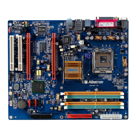
This function is for detecting the system when it is unable to handle over-clocking configurations during the POST stage. Once the problem is detected, the system will reset the configurations and reboot the system within five seconds. Configuration Layout of PX915-DV... -
Page 9: Hardware Installation
Mainboard PX915-DV Hardware Installation This section will assist you in quickly installing your system hardware. Wear a wrist ground strap before handling components. Electrostatic discharge may damage the system’s components. -
Page 10: Cpu Processor Installation
Mainboard PX915-DV CPU Processor Installation ® ® This mainboard supports Intel Pentium 4 processors Socket 775. Before building your system, we suggest you to visit the Intel website and review the processor installation procedures. http://www.intel.com CPU Socket 775 Configuration Steps: 1. -
Page 11: Memory Installation
Memory Installation: DIMM1/2 The PX915-DV provides two DIMM (Dual In-Line Memory Modules) sockets which you can insert 184-pin non-ECC, unbuffered DDR SDRAMs. The DIMMs also support DDR400 (PC3200)/ DDR333 (PC2700) and dual channel technology. It supports a total memory capacity of 2 GB. -
Page 12: Back Panel Configuration
Mainboard PX915-DV Setup Steps: 1. Pull the white plastic tabs at both ends of the socket away. 2. Align a memory on the socket such that the notch on the memory matches the break on the socket. 3. Lower the memory vertically into the socket and press firmly by using both thumbs until the memory snaps into place. - Page 13 Mainboard PX915-DV PS/2 Mouse & PS/2 Keyboard Ports: KB/MS This mainboard provides a standard PS/2 mouse port and a PS/2 keyboard port. The pin assignments are described below. PS/2 Mouse Assignment Assignment Data +5 V (fused) No connect Clock Ground...
-
Page 14: Connectors
Mainboard PX915-DV Assignment Assignment +5 V (fused) USBP0+/P1+ USBP0-/P1- Ground Audio Ports: Sound This mainboard provides three audio ports, the Mic-in, Line-in and Line-out. These are the standard audio ports that provide basic audio function. Line-In (Blue) This port is for audio input and connects to external audio devices such as CD player, tape player, etc. -
Page 15: Front Panel Headers
Mainboard PX915-DV Floppy Disk Drive Connector: FDC The mainboard provides a standard floppy disk drive connector (FDC) that supports 360KB/ 720KB/1.2MB/1.44MB/2.88MB floppy disk drives using a FDD ribbon cable. Hard disk drive Connectors: The mainboard provides one IDE connector that supports Ultra ATA 66/100/133 IDE devices. You can attach a maximum of two IDE devices, such as hard disk drive (HDD), CD-ROM, DVD-ROM, etc. -
Page 16: Headers & Jumpers
Mainboard PX915-DV Hard Drive LED Header (Red): HD LED If your PC front panel has a hard drive LED cord, please attach it to this header. The LED will flicker during the hard disk drive activity. Reset Switch Header (Blue): RST SW This header can be attached to a momentary SPST switch cord on your PC front panel. - Page 17 Mainboard PX915-DV Front USB Headers: USB3/4 The mainboard provides four USB 1.1/2.0 ports for you to attach USB devices, and two USB headers provided can allow you to set more USB ports on your PC front panel. Attach a USB cable (optional) to these two headers so you can set additional four USB ports to use.
-
Page 18: Audio Configuration
Mainboard PX915-DV The following steps explain how to reset your CMOS configurations when you Audio have forgotten your system password. 1. Turn off your system and disconnect the AC power cable. 2. Set JP1 header to OFF (2-3 Closed). 3. Wait several seconds. -
Page 19: Slots
Mainboard PX915-DV CD-ROM Audio-In Connector: CD-IN This header is used to attach an audio cable to audio resources, such as CD-ROM, DVD-ROM…etc. S/PDIF header: SPDIF S/PDIF is a recent audio transfer file format, which provides high quality audio using optical fiber and digital signals. -
Page 20: Power Supply Attachments
Mainboard PX915-DV insert an expansion card which the interface is capable for PCI-E x16 specification (i.e., a graphics card) onto the other slot, PCI-E1. PCI Interface Slots: PCI1/2 This mainboard provides two standard 32-bit PCI slots. PCI stands for Peripheral Component Interconnect and is a bus standard for expansion cards, which has supplanted the older ISA bus standard. -
Page 21: Plug And Play Support
Mainboard PX915-DV Plug and Play Support This PHOENIX-AWARD™ BIOS supports the Plug and Play Version 1.0A specification as well as ESCD xtended System Configuration Data) write. EPA Green PC Support This PHOENIX-AWARD™ BIOS supports the Version 1.03 of EPA Green PC specification. -
Page 22: Main Menu
Mainboard PX915-DV Keystroke Function Up arrow Move to previous option Down arrow Move to next option Left arrow Move to the option on the left (menu bar) Right arrow Move to the option on the right (menu bar) Main Menu: Quit without saving changes... -
Page 23: Advanced Bios Features
Mainboard PX915-DV Option Options Description Set the system d ate. Note that the ‘Day’ Date mm dd yyyy automatically c hanges when you set the date. Time Hh: mm: ss Set the current time of the system. IDE Cha nnel 0... - Page 24 Mainboard PX915-DV Removable Device Priority Select removable device priority. Just like floppy, LS120, ZIP-100, USB-FDD and USB-ZIP. Hard Disk Boot Priority Select hard disk boot priority. First /Second/Third B oot Device Select the order in which devices will be searched in or der to find a boot device.
-
Page 25: Typematic Rate Setting
Mainboard PX915-DV Excute Disable Bit It can prevent viruses invaded while the programmable processing. irus Warning is option allows you to choose the Virus Warning feature for IDE Hard Disk boot sector protection. If this function is enabled and someone attempts to write data into thia area, BIOS will display a warning message on the screen and sound an audio alarm (beep). -
Page 26: Advanced Chipset Features
Mainboard PX915-DV MPS Version Control For OS e 1.1 version is the older version that supports 8 more IRQs in the Windows NT environment. Choose the new 1.4 version for Windows 2000 and Windows XP. Options: 1.4 (default),1.1 S Select For DRAM > 64MB lect “OS2”... -
Page 27: Reset Configuration Data
Mainboard PX915-DV DRAM RAS# Precharge is option allows you to select t he DRAM RAS# precharged time. The ROW address strobe must be precharged again before DRAM is refreshed. An inadequate configuration may result in incomplete data. This option is adjustable only when “DRAM Timing Selectable” is set to “manual”. This option locked when “DRAM Timing Selectable”... -
Page 28: Maximum Payload Size
Mainboard PX915-DV esources Controlled By BIOS can automatically configure all the boot and Plug and Play compatible devices. If you choose Auto, you will not be able to manually assign IRQ DMA and memory base address options, since BIOS automatically assigns them. - Page 29 Mainboard PX915-DV CI-E Speed Setting This option determines the PCI-E frequency (speed settings). You can set the frequency using the supplied BIOS options. One of the options available to you is “Auto”. Using the “Auto” option will instruct the system to automatically calculate the frequency.
-
Page 30: Peripherals
Mainboard PX915-DV Peripherals Init Display First With systems that have multiple video cards, this option determines whether the primary display uses a PCI slot or an AGP slot. Options: PCIEx (default),PCI Slot OnChip IDE Device E HDD Block Mode Block mode is otherwise known as block transfer, multiple commands, or multiple sector read/write. -
Page 31: Onchip Serial Ata Setting
Mainboard PX915-DV E channel0/ channel1/Master/Slave PIO The IDE PIO (Programmed Input / Output) options let you set a PIO mode (0-4) for each of the IDE devices that the onboard IDE interface supports. Modes 0 to 4 will increase performance incrementally. -
Page 32: Onboard Device
Mainboard PX915-DV ATA Port This option will display which IDE channel will be used to the SATA device. Options: SATA2, 4 is channel 1 Onboard Device SB Controller This option should be enabled if your system has a USB port installed on the system board. You will need to disable this feature if you add a higher performance controller. - Page 33 Mainboard PX915-DV xD, TxD Active This option determines the RxD and TxD frequencies. This option is configurable only if “UART Mode Select” is set to “IrDA”. Options: Hi / Lo (default),Hi / Hi,Lo / Hi,Lo / Lo Transmission Delay This option allows you to enable/disable IR transmission delay. This option is configurable only if “UART Mode Select”...
-
Page 34: Power Management
Mainboard PX915-DV WRON After PWR-Fail This option will determine whether your system will boot after restoring power after a power failure. If you select “On”, the system will boot whether or not the system was on before power failure. If you select “Former-Sts”, the system will be restored to the status before the power failure. -
Page 35: Video Off Method
Mainboard PX915-DV S1 & S3 POS and STR Run VGABIOS if S3 Resume Select whether you want to run VGABIOS when the system wakes up from the S3 suspend function. This option is not configurable if “ACPI Suspend Type” is set to “S1(POS)”. -
Page 36: Suspend Mode
Mainboard PX915-DV Suspend Mode This option allows you to select the suspend time under the ACPI operating system. Options: Disabled(default),1Min,2Min,4Min,8Min,12Min,20Min,30Min,40Min,1Hour HDD Power Down When enabled, the hard disk drive will power down after a certain configurable period of system inactivity. All other devices remain active. -
Page 37: Hardware Monitor
Mainboard PX915-DV include: Primary IDE 0/ Primary IDE 1/ Secondary IDE 0/ Secondary IDE 1/ FDD,COM,LPT Port/ PCI PIRQ [A-D]#. Options: Disabled (default), Enabled Hardware Monitor Case Open Warning If this option is set to “Enabled” and the case had been previously opened, the system will automatically display alert messages on the screen when you power on your computer. -
Page 38: Defaults
Mainboard PX915-DV Defaults Load System Default Settings Load System Default Settings. Load System Turbo Settings Load System Turbo Settings. Load CMOS From BIOS Load defaults from flash ROM for systems without batteries. Save CMOS To BIOS Save defaults to flash ROM for systems without batteries. -
Page 39: Chapter 3: Software Setup
Mainboard PX915-DV Save & Exit Setup Save all configuration changes to CMOS (memory) and exit setup. A confirmation message will be displayed before proceeding. Exit Without Saving Abandon all changes made during the current session and exit setup. A confirmation message will be displayed before proceeding. - Page 40 Mainboard PX915-DV are several buttons displayed in the main screen as shown below. PX915-DV Intel Chipset INF – It provides all drivers for the functions which built in both the Northbridge/ Southbridge Realtek AC’97 Audio Driver – It provides the driver of Realtek AC’97 Audio Codec Realtek Network Driver –...
-
Page 41: Chapter 4: Troubleshooting
Mainboard PX915-DV 4. Click “Exit” button to exit the program. Chapter 4: Troubleshooting Problem 1: No power to the system. Power light does not illuminate. Fan inside power supply does not turn on. Indicator lights on keyboard are not lit. - Page 42 Mainboard PX915-DV 2. Contact technical support. 3. Backing up the hard drive is extremely important. Make sure your periodically perform backups to avoid untimely disk crashes. Problem 4: System only boots from the CD-ROM. The hard disk can be read and applications can be us but booting from the hard disk is impossible.
- Page 43 Mainboard PX915-DV Problem 10: Keyboard failure. Causes: Keyboard is disconnected. Solutions: Reconnect keyboard. Replace keyboard if you continue to experience problems. Problem 11: No color on screen. Causes: 1. Faulty Monitor. 2. CMOS incorrectly set up. Solutions: 1. If possible, connect monitor to another system. If no color appears, replace monitor.
-
Page 44: Ppendix Ii: Abs
2. Click Speaker Test button, you can see the screen like the pictures below. 3. Select the speaker which you want to test by clicking on it. 2 Channels 4 Channels 6 Channels Subwoofer Front Right Front Left Rear Right Rear Left Center Appendix II: ABS (Albatron BIOS... - Page 45 Mainboard PX915-DV Security) Card Setup Introduction The ABS (Albatron BIOS Security) system provides your system with a recovery BIOS backup when your onboard BIOS has been damaged beyond system boot capability. Preparation and Setup You should prepare a boot floppy disk and have it ready in case of such BIOS failures. Otherwise you will have to find another computer to make the boot floppy disk from.
- Page 46 Mainboard PX915-DV Once in the BIOS Utility, follow this path: Advanced -> Hard Disk Boot Priority -> First Boot Device and set the “First Boot Device” to “Removable”. After the system boots from the floppy, the system will enter into the DOS mode (note that the system has booted using the ABS card’s BIOS).
- Page 47 Mainboard PX915-DV The next screen (shown above-right) will display a message “Press ’Y’ to Program or ‘N’ to Exit”. Then type ‘Y’ to begin the onboard BIOS flash procedure. 9. The flashing procedure will take several minutes and will show its progress on the screen. After the flash BIOS procedures have completed, press ‘F1’...
- Page 48 Mainboard PX915-DV Follow the path: Defaults -> Load System Default Settings -> Y . Next, follow the path: Exit -> Save & Exit Setup -> Y Follow the path: Exit -> Save & Exit Setup -> Y . 11. After you have recovered your onboard BIOS, you can choose to remove or not remove the ABS Card from the mainboard.
- Page 49 Mainboard PX915-DV If you choose not remove the ABS Card from the mainboard, make sure that the jumper caps on the ABS_JP1 header located on the ABS Card to the “Onboard BIOS” as below, in order to reduce the damage opportunity of the rescue BIOS in ABS Card and on the other hand to extend the usage life of the ABS Card.
Need help?
Do you have a question about the PX915-DV and is the answer not in the manual?
Questions and answers