Table of Contents
Advertisement
Copyright
All rights are reserved. No part of this publication may be reproduced, transmitted, transcribed, stored in a
retrieval system or translated into any language or computer language, in any form or by any means,
electronic, mechanical, magnetic, optical, chemical, manual or otherwise, without the prior written
permission of the company. Brands and product names are trademarks or registered trademarks of their
respective companies.
The vendor makes no representations or warranties with respect to the contents herein and especially
disclaim any implied warranties of merchantability or fitness for any purpose. Further the vendor reserves
the right to revise this publication and to make changes to the contents herein without obligation to notify
any party beforehand. Duplication of this publication, in part or in whole, is not allowed without first
obtaining the vendor's approval in writing.
Trademark
All the trademarks or brands in this document are registered by their respective owner.
Disclaimer
We make no warranty of any kind with regard to the content of this user's manual. The content is subject
to change without notice and we will not be responsible for any mistakes found in this user's manual. All
the brand and product names are trademarks of their respective companies.
FCC Compliance Statement
This equipment has been tested and found to comply with the limits of a Class B digital device, pursuant to
Part 15 of the FCC Rules. These limits are designed to provide reasonable protection against harmful
interference in a residential installation. This equipment generates, uses and can radiate radio frequency
energy and, if not installed and used in accordance with the instructions, may cause harmful interference
to radio communications. Operation of this equipment in a residential area is likely to cause harmful
interference in which case the user will be required to correct the interference at his own expense.
However, there is no guarantee that interference will not occur in a particular installation.
CE Mark
The device is in accordance with 89/336 ECC-ENC Directive.
Ver: EG103
PXP965 (V2.0)
Advertisement
Table of Contents

Related Manuals for Albatron PXP965 (V2.0)


Summary of Contents for Albatron PXP965 (V2.0)
-
Page 1: Fcc Compliance Statement
PXP965 (V2.0) Copyright All rights are reserved. No part of this publication may be reproduced, transmitted, transcribed, stored in a retrieval system or translated into any language or computer language, in any form or by any means, electronic, mechanical, magnetic, optical, chemical, manual or otherwise, without the prior written permission of the company. - Page 2 Mainboard PXP965 (V2.0) PXP965 (V2.0) ® Intel P965 & ICH8 ® Support Socket 775 Intel Core 2 Extreme/ Core 2 Duo/ ® ® Pentium Extreme Edition/ Pentium 4 Extreme Edition/ ® ® ® Pentium D/ Pentium 4/Celeron D Processor User Manual Enabling the Hyper-Threading Technology, your computer system is required to have components as the following: ®...
-
Page 3: Packing List
Mainboard PXP965 (V2.0) Things You Have To Know The images and pictures in this manual are for reference only and may vary from the product you received depending on specific hardware models, third party components and software versions. This mainboard contains very delicate IC chips. Always use a grounded wrist strap when working with the system. -
Page 4: Table Of Contents
Mainboard PXP965 (V2.0) Table of Contents CHAPTER 1. GETTING STARTED ..............1 ....................... 1 NTRODUCTION ....................... 2 PECIFICATION ....................5 ONFIGURATION Layout of PXP965 (V2.0)................5 ................... 6 ARDWARE NSTALLATION CPU Processor Installation................6 Memory Installation: DIMM1/2/3/4..............7 Back Panel Configuration................9 Connectors..................... -
Page 5: Chapter 1. Getting Started
Mainboard PXP965 (V2.0) Chapter 1. Getting Started Introduction ® Thanks for choosing PXP965 (V2.0) Mainboard. It is based on Intel P965 Northbridge chipset ® ® and Intel ICH8 Southbridge chipset. It supports Intel Core 2 Extreme/ Core 2 Duo/ ® ®... -
Page 6: Specification
Mainboard PXP965 (V2.0) Specification CPU: Support Socket 775 ® ® ® Support Intel Core 2 Extreme/ Core 2 Duo/ Pentium Extreme Edition/ Pentium ® ® ® 4 Extreme Edition/ Pentium D/ Pentium 4/ Celeron D Processor Support Hyper-Threading Technology Support 1066 MHz/ 800 MHz/ 533 MHz FSB (Front Side Bus) Frequencies Chipset: ®... -
Page 7: Fdd Connector
Mainboard PXP965 (V2.0) 1. One PCI-E x16 slot: Supports up to x16 mode 2. One Universal PCI-E slot: Supports up to x4 mode 3. Two PCI-E x1 slot: Supports up to x1 mode Two PCI interface slots for expansion cards FDD Connector: Supports one FDD connector to set up to two floppy disk drives Supports 360KB/ 720KB/ 1.2MB/ 1.44MB/ 2.88MB... -
Page 8: Universal Serial Bus
Mainboard PXP965 (V2.0) devices connected Universal Serial Bus: Four onboard USB 2.0/ 1.1 ports Three front USB headers come with this mainboard for additional six USB ports Support a maximum of ten USB ports to connect USB compliant devices BIOS: Phoenix-Award™... -
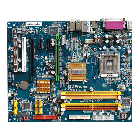
Page 9: Configuration
Mainboard PXP965 (V2.0) Configuration Layout of PXP965 (V2.0) -
Page 10: Hardware Installation
Mainboard PXP965 (V2.0) Hardware Installation This section will assist you in quickly installing your system hardware. Wear a wrist ground strap before handling components. Electrostatic discharge may damage the system’s components. CPU Processor Installation ® ® ® This mainboard supports Intel Core 2 Extreme/ Core 2 Duo/ Pentium... -
Page 11: Memory Installation: Dimm1/2/3/4
Mainboard PXP965 (V2.0) FAN Headers: CPUFAN, SYSFAN1, SYSFAN2 There are three fan headers available for cooling fans. The cooling fans play an important role in maintaining ambient temperatures in your system. The CPUFAN header is attached with a CPU cooling fan. - Page 12 Mainboard PXP965 (V2.0) Attention It is recommended that to install memories which are identical specifications (same timing specifications and same DDR II speed) to achieve the best effects. It may cause the failure of power-on or lower memory speed if installing different type, SPD (series presence detects) memories.
-
Page 13: Back Panel Configuration
Mainboard PXP965 (V2.0) Lower the RAM module into the DIMM Slot and press firmly using both thumbs until the module snaps into place. Repeat steps 1, 2 & 3 for the remaining RAM modules. * The pictures above are for reference only. Your actual installation may vary slightly from the pictures. - Page 14 Mainboard PXP965 (V2.0) Serial and Parallel Interface Ports The mainboard provides one serial port and one parallel port on the back panel. Parallel Interface Port: PARALLEL The parallel port on your mainboard is a standard 25-pin one, and is used to connect a parallel printer. The Serial Interface: COM1 This mainboard provides a serial port COM1 on your back panel, and is used to connect mice, modem and other peripheral devices.
-
Page 15: Connectors
Mainboard PXP965 (V2.0) Line-Out (green) This port is an output audio port used for connecting to speakers or a headset. A dual channel audio system is to provide basic audio functionality. When the 8/6/4/2 channel audio system is enabled, this port will output audio for the front speakers. -
Page 16: Front Panel Headers: Jw_Fp, Pwrled, Speak
Mainboard PXP965 (V2.0) The IDE connector supports Ultra ATA 66/100/133 IDE devices. You can attach a maximum of two IDE devices, such as hard disk drive (HDD), CD-ROM, DVD-ROM, etc. using an IDE ribbon cable. In general, two IDE devices can be attached onto one IDE connector. If you attach two IDE HDDs, you must configure one drive as the master and the other one as the slave. - Page 17 Mainboard PXP965 (V2.0) Hard Drive LED Header: HDLED If your case front panel has a hard drive LED cable, attach it to this header. The LED will flicker when there is hard disk drive activity. Reset Switch Header: RESET This header can be attached to a momentary SPST switch (reset button) cable on your case front panel. The switch is normally left open.
-
Page 18: Ez Control Button
Mainboard PXP965 (V2.0) EZ Control Button Onboard Buttons: POWER, RESET The mainboard provides one Power Switch and one Reset Switch buttons for your convenience to turn on or restart your system. If pressing one of them, then you can start your computer easily before the mainboard is set into the case. - Page 19 Mainboard PXP965 (V2.0) Front USB Headers: USB2/3/4 This mainboard provides four onboard USB 1.1/2.0 ports (back panel) that attach to USB devices. There are three additional USB headers that can be connected by cables to six more USB ports on the front panel of your case giving you a possible ten USB ports.
-
Page 20: Audio Configuration
Mainboard PXP965 (V2.0) JP2/ JP3 Assignment Assignment USB Power On Disable (Default) Pin 1-2 Closed USB Power On Enabled +5VSB Pin 2-3 Closed Note: Close stands for putting a jumper cap onto two header pins. Clear CMOS Jumper: JBAT The “Clear CMOS” function is used when you are unable boot your system and need to reset the BIOS settings (CMOS settings) back to the manufacturer’s original settings. -
Page 21: Slots
Mainboard PXP965 (V2.0) Front Panel Audio Header: AUDIO If your case front panel has audio ports, you can connect them to the Front Audio Header of this mainboard. Therefore, you can use both the front audio panel and back panel audio simultaneously. AUDIO Assignment Assignment... -
Page 22: Power Supply Attachments
Mainboard PXP965 (V2.0) Power Supply Attachments PCIE Power Connector: J1 The 4-pin connector provides an extra +12V for the PCI-E x16 slot in order to increase the stability of your graphics card. You can attach the 4-pin connector to power supply directly. ATX Power Connector: ATXPWR, ATX12V This mainboard provides two ATX power connectors, a 24-pin ATXPWR connector and an 8-pin ATX12V connector. -
Page 23: Chapter 2. Bios Setup
Mainboard PXP965 (V2.0) Chapter 2. BIOS Setup Introduction This section describes PHOENIX-AWARD™ BIOS Setup program which resides in the BIOS firmware. The Setup program allows users to modify the basic system configuration. The configuration information is then saved to CMOS RAM where the data is sustained by battery after power-down. The BIOS provides critical low-level support for standard devices such as disk drives, serial ports and parallel ports. -
Page 24: Main Menu
Mainboard PXP965 (V2.0) Main Menu Standard CMOS Features Include all the adjustable items in standard compatible BIOS. Advanced BIOS Features Include all the adjustable items of Award special enhanced features. Advanced Chipset Features Include all the adjustable items of chipset special features. Integrated Peripherals Include all onboard peripherals. -
Page 25: Miscellaneous Control
Mainboard PXP965 (V2.0) Miscellaneous Control It is for you to specify settings for Miscellaneous Control, such as the CPU clock and frequency ratio. Attention Before going to update BIOS, please change the item, 【 Miscellaneous Control】 → 【Flash Write Protect】, from【Enabled】to【Disabled】. When the BIOS update is done, please adjust the item from【Disabled】to【Enabled】. -
Page 26: Chapter 3: Software Setup
Mainboard PXP965 (V2.0) Chapter 3: Software Setup Software List Category Platform ® Windows 2000 /XP Intel Chipset INF ® Windows 2000 /XP Realtek Lan Driver ® Windows 2000 /XP Realtek Audio Driver ® Windows 2000/ XP JMicron JMB363 RAID Driver ®... - Page 27 Mainboard PXP965 (V2.0) Intel Chipset INF – It provides all drivers for the functions which built in both the Northbridge/ Southbridge. Realtek LAN Driver – It provides the driver of Realtek Network. Realtek Audio Driver – It provides the driver of Realtek AC’97 Audio CODEC.
- Page 28 Mainboard PXP965 (V2.0) Adobe Acrobat Reader 6 – Installing the Adobe Acrobat Reader program, you can browse files with PDF styled. Click on the “User Manual” button, you can choose the manual to read. Attention: Before you read manuals, you must install the driver of Adobe Acrobat Reader 6 to browse PDF files.
-
Page 29: Chapter 4: Troubleshooting
Mainboard PXP965 (V2.0) Chapter 4: Troubleshooting Problem 1: No power to the system. Power light does not illuminate. Fan inside power supply does not turn on. Indicator lights on keyboard are not lit. Causes: 1. Power cable is unplugged. 2. Defective power cable. 3. - Page 30 Mainboard PXP965 (V2.0) Problem 4: System only boots from the CD-ROM. The hard disk can be read and applications can be used but booting from the hard disk is impossible. Causes: Hard Disk boot sector has been corrupted. Solutions: Back up data and applications files. Reformat the hard drive. Re-install applications and data using backup disks.
- Page 31 Mainboard PXP965 (V2.0) Problem 10: Keyboard failure. Causes: Keyboard is disconnected. Solutions: Reconnect keyboard. Replace keyboard if you continue to experience problems. Problem 11: No color on screen. Causes: 1. Faulty Monitor. 2. CMOS incorrectly set up. Solutions: 1. If possible, connect monitor to another system. If no color appears, replace monitor. 2.
-
Page 32: Appendix I: 8/6/4/2 Channel Audio Effect Setup
Mainboard PXP965 (V2.0) Appendix I: 8/6/4/2 Channel Audio Effect Setup Channels Setup After into the system, click the audio icon from the Windows screen. Click “Audio I/O” button, you can see the screen like the picture below. You can choose 2, 4, 6 or 8 channels by your speakers. You can click the “Auto test”... -
Page 33: Appendix Ii: Sata 0/1 Specification
Mainboard PXP965 (V2.0) Appendix II: SATA 0/1 Specification Introduction to RAID (Redundant Array of Independent Disks) RAID technology is a sophisticated disk management system that manages multiple disk drives, enhancing I/O performance and providing redundancy in order to prevent the loss of data in case any of the individual disks fail. -
Page 34: Appendix Iii: Ide Cd-Rom/ Dvd-Rom Setup
Mainboard PXP965 (V2.0) Appendix III: IDE CD-ROM/ DVD-ROM Setup The PXP965 (V2.0) provides one IDE chip (JMicron) for IDE device use. If you are installing the operating system using a CD-ROM/ DVD-ROM, you need to know how to set up these devices. There are two ways configure your CD-ROM/ DVD-ROM which will be explained in two sections below. - Page 35 Mainboard PXP965 (V2.0) Select the name of the CD-ROM/ DVD-ROM that will be configured into your computer (do not select the item “CDROM”). For instance, the system for the screen below has a “PIONEER DVD-ROM”. Press【Enter】. Your computer will reboot and read the CD-ROM/ DVD-ROM. Configuring the CD-ROM/DVD-ROM in the BIOS Setup Utility →...
- Page 36 Mainboard PXP965 (V2.0) Move the arrow keys to the “Advanced BIOS Features” item and press【Enter】. After entering the sub-menu, arrow down to the “First Boot Device” item. Press【Enter】.
- Page 37 Mainboard PXP965 (V2.0) A selection box will appear listing several devices. Notice that you can’t select the “CDROM” item. Scroll down the list to locate your CD-ROM/ DVD-ROM. Select it and press【Enter】. Confirm that the “First Boot Device” item contains your selection (e.g. “First Boot Device” is “PIONEER DVD-ROM”).
- Page 38 Mainboard PXP965 (V2.0) At the main screen arrow over to the “Save & Exit” item. Press【Enter】. Finally, press “Y”, and then press 【Enter】 to finish the setup. Wait for your computer to reboot and read your CD-ROM/ DVD-ROM.
Need help?
Do you have a question about the PXP965 (V2.0) and is the answer not in the manual?
Questions and answers