Table of Contents
Advertisement
Quick Links
PX925X/PX925XE Series
Copyright
All rights are reserved. No part of this publication may be reproduced, transmitted,
transcribed, stored in a retrieval system or translated into any language or computer
language, in any form or by any means, electronic, mechanical, magnetic, optical,
chemical, manual or otherwise, without the prior written permission of the company.
Brands and product names are trademarks or registered trademarks of their respective
companies.
The vendor makes no representations or warranties with respect to the contents herein
and especially disclaim any implied warranties of merchantability or fitness for any
purpose. Further the vendor reserves the right to revise this publication and to make
changes to the contents herein without obligation to notify any party beforehand.
Duplication of this publication, in part or in whole, is not allowed without first obtaining
the vendor's approval in writing.
Trademark
All the trademarks or brands in this document are registered by their respective owner.
Disclaimer
We make no warranty of any kind with regard to the content of this user's manual. The
content is subject to change without notice and we will not be responsible for any
mistakes found in this user's manual. All the brand and product names are trademarks of
their respective companies.
FCC Compliance Statement
This equipment has been tested and found to comply with the limits of a Class B digital
device, pursuant to Part 15 of the FCC Rules. These limits are designed to provide
reasonable protection against harmful interference in a residential installation. This
equipment generates, uses and can radiate radio frequency energy and, if not installed
and used in accordance with the instructions, may cause harmful interference to radio
communications. Operation of this equipment in a residential area is likely to cause
harmful interference in which case the user will be required to correct the interference
at his own expense. However, there is no guarantee that interference will not occur in a
particular installation.
CE Mark
The device is in accordance with 89/336 ECC-ENC Directive.
Ver: EG101
120410109M2N
Advertisement
Table of Contents

Related Manuals for Albatron PX925XE Series


Summary of Contents for Albatron PX925XE Series
-
Page 1: Fcc Compliance Statement
PX925X/PX925XE Series Copyright All rights are reserved. No part of this publication may be reproduced, transmitted, transcribed, stored in a retrieval system or translated into any language or computer language, in any form or by any means, electronic, mechanical, magnetic, optical, chemical, manual or otherwise, without the prior written permission of the company. -
Page 2: Package Contents
Do not touch the IC chips, leads, connectors or other components. Unplug the AC power when you install or remove any device on the mainboard. Package Contents PX925X/ PX925XE Series mainboard IDE ATA Cable FDC Cable USB Bracket (optional) Game Port Bracket (optional) SPDIF &... -
Page 3: Operating System
PX925X/PX925XE Series ® Intel 925X/925XE & ICH6/ICH6R/ICH6RW ® ® Supports Socket 775 Intel Pentium Prescott Processor User Manual Enabling Hyper-Threading for your computer system requires ALL of the following components CPU: An Intel ® Pentium ® 4 Processor with HT Technology Chipset: An Intel ®... -
Page 4: Table Of Contents
CHAPTER 1. GETTING STARTED .............1 ......................1 NTRODUCTION ......................2 PECIFICATION Configuration......................5 Layout of PX925XE PRO ..................5 Layout of PX925XE PRO-R ................6 Layout of PX925X....................7 Layout of PX925X-R.................... 8 Layout of PX925X PRO..................9 Layout of PX925X PRO-R................. 10 .................. -
Page 5: Chapter 1. Getting Started
Congratulations on choosing from the PX925X/ PX925XE series of mainboards! The PX925X series includes the PX925X, PX925X-R, PX925X PRO and PX925X PRO-R. The PX925XE series includes the PX925XE PRO and PX925XE PRO-R. These mainboards are based on the Intel ®... -
Page 6: Dram Memory
FSB (Front Side Bus) 800/1066 MHz (for PX925XE series) Chipset: Northbridge Chipset – Intel® 925X/925XE Southbridge Chipset – Intel® ICH6 for PX925X/ PX925X PRO/ PX925XE PRO Intel® ICH6R for PX925X-R/ PX925PRO-R/ PX925XE PRO-R I/O Controller – Winbond W83627THF RAID IDE Controller – ITE IT8212F HD Aduio Codec –... -
Page 7: Universal Serial Bus
Onboard SATA Bus: 4 SATA IDE slots SATA 1.0 compatible Supports 150 MB/s transfer rates Supports RAID 0, RAID 1 modes (for PX925X-R/ PX925X PRO-R /PX925XE PRO-R only) Hardware Monitor Function: Monitors CPUFAN/ CHASFAN/ AUXFAN Speeds Monitors system Voltage HD Audio Sound Codec Onboard:... -
Page 8: Watch Dog Timer
LAN Controller: Broadcom BCM5789 LAN controller supports Ethernet 10/100/1000 Mbit/s connectivity. The PX925X PRO/ PRO-R and the PX925XE PRO/ PRO-R provide an additional LAN facility using a built-in VIA® VT6105 chipset which supports Ethernet 10/100 Mbit/s network connectivity. I/O facilities:... -
Page 9: Configuration
PX925X/PX925XE Series Configuration Layout of PX925XE PRO... -
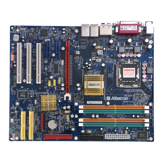
Page 10: Layout Of Px925Xe Pro-R
PX925X/PX925XE Series Layout of PX925XE PRO-R... -
Page 11: Layout Of Px925X
PX925X/PX925XE Series Layout of PX925X... -
Page 12: Layout Of Px925X-R
PX925X/PX925XE Series Layout of PX925X-R... -
Page 13: Layout Of Px925X Pro
PX925X/PX925XE Series Layout of PX925X PRO... -
Page 14: Layout Of Px925X Pro-R
PX925X/PX925XE Series Layout of PX925X PRO-R... -
Page 15: Hardware Installation
PX925X/PX925XE Series Hardware Installation This section will assist you in quickly installing your system hardware. Wear a wrist ground strap before handling components. Electrostatic discharge may damage the system’s components. CPU Processor Installation This mainboard supports Intel Pentium 4 processors using a Socket 775. Before building ®... -
Page 16: Fan Headers
PX925X/PX925XE Series FAN Headers Three power headers are available for the cooling fans. Cooling fans play an important role in maintaining the ambient temperature in your system. Attention: We strongly recommend that you use a CPU fan sink with your CPU. You can attach the power cable from the CPU fan sink to the CPUFAN Header. -
Page 17: Ram Module Installation
PX925X/PX925XE Series How to enable Dual-Channel DDRII: These mainboards provide Dual-Channel functionality for its DIMM slots. Enabling Dual-Channel can significantly increase your data access rates. DIMM1 and DIMM2 share one channel, while DIMM3 and DIMM4 share the second channel. Enabling Dual-Channel simply means to make sure that the total memory for the two channels are balanced. -
Page 18: Back Panel Configuration
PX925X/PX925XE Series Back Panel Configuration PS/2 Mouse & PS/2 Keyboard Connectors: KB/MS These mainboards provide a standard PS/2 mouse connector and PS/2 keyboard connector. The pin assignments are described below: Assignment Assignment Data +5 V (fused) No connect Clock Ground... - Page 19 These mainboards come with 4 USB ports and a Gb/s LAN port. The PX925X PRO/ PRO-R and PX925XE PRO/ PRO-R have secondary additional 10/100 Mbit/s LAN port. The USB connectors are used to attach to keyboards, mice and other USB devices. You can plug the USB devices directly into this connector.
-
Page 20: Connectors
SATA1-4 (Serial ATA connectors) These SATA connectors support Serial ATA 150 and the PX925X-R/ PX925PRO-R/ PX925XE PRO-R supports RAID 0/ 1 modes. Each SATA connector can only support one serial ATA device. Note: With most storage devices, there is a power cable that you need attach to a... -
Page 21: Front Panel Indicator: Sw/Led、Pwrled、Speaker
PX925X/PX925XE Series Front Panel Indicator: SW/LED、PWRLED、SPEAKER HD LED (Hard Drive LED Connector/ red) This connector can be attached to an LED on the front panel of a computer case. The LED will flicker during any disk activity. RST SW (Reset Connector/ blue) This connector can be attached to a momentary SPST switch. -
Page 22: Headers & Jumpers
PX925X/PX925XE Series Headers & Jumpers Infrared Header: IrDA You can attach an infrared device to this connector and use this connector for connectionless infrared data transfers. Game Port Header: GAME PORT There is a game port header on these mainboards. To use this header, you must attach a game port bracket-cable so that you can interface to gaming devices (game port bracket is optional). - Page 23 PX925X/PX925XE Series Clear CMOS Jumper: JP1 The “Clear CMOS” jumper allows you to reset your CMOS configurations. This is particularly useful when you have forgotten your system password and cannot boot to the operating system. The following steps explain how to reset your CMOS configurations when you have forgotten your system password.
-
Page 24: Audio Connectors
PX925X/PX925XE Series Audio Connectors CD-ROM Audio-In Header: CD-IN This header is used to connect to the CD-ROM/DVD audio cable Front Panel Audio Header (Orange): FRONT AUDIO You can use the Front Panel Audio header (FRONT AUDIO) to connect to a separate audio bracket or to connect to case embedded audio equipment. -
Page 25: Slots
PX925X/PX925XE Series SPDIF & FRONT AUDIO bracket You can connect this bracket to the SPDIF and FRONT AUDIO Headers. SPDIF IN SPDIF Micro (RCA OUT (RCA Phone IN SPDIF Conn.) SPDIF IN Conn.) (TOS-Link Phone (Tos-Link Conn.) Conn.) Slots These slots are designed for expansion cards to complement and enhance the functionality of the mainboard. -
Page 26: Power Supply Attachments
PX925X/PX925XE Series Power Supply Attachments ATX Power Connector: ATX_PWR、ATX_12V This mainboard requires two ATX power connections. The first is a 24-pin connector and the second is a 4-pin connector. Attach the 4-pin connector first and then attach the 24-pin connector. Make sure the connectors are secure before applying power. (ATX_PWR... -
Page 27: Chapter 2. Bios Setup
PX925X/PX925XE Series Chapter 2. BIOS Setup Introduction This section describes PHOENIX-AWARD™ BIOS Setup program which resides in the BIOS firmware. The Setup program allows users to modify the basic system configuration. The configuration information is then saved to CMOS RAM where the data is sustained by battery after power-down. -
Page 28: Key Function
PX925X/PX925XE Series Supported CPUs This PHOENIX-AWARD™ BIOS supports the Intel Pentium 4 CPUs. ® ® Key Function In general, you can use the arrow keys to highlight items, press <Enter> to select, use the <PgUp> and <PgDn> keys to change entries, press <F1> for help and press <Esc>... -
Page 29: Main Menu
PX925X/PX925XE Series Main Menu When you enter the PHOENIX-AWARD™ BIOS Utility, the Main Menu will appear on the screen. The Main menu allows you to select from several configuration options. Use the left/right arrow keys to select a particular configuration screen from the top menu bar... - Page 30 PX925X/PX925XE Series Main Menu Setup Configuration Options Item Options Description Set the system date. Note that the ‘Day’ automatically Date mm dd yyyy changes when you set the date. Time Hh: mm: ss Set the current time of the system.
-
Page 31: Advanced Bios Features
PX925X/PX925XE Series Advanced BIOS Features Removable Device Priority Select removable device priority. Just like floppy, LS120, ZIP-100, USB-FDD and USB-ZIP. Hard Disk Boot Priority Select hard disk boot priority. CD-ROM Boot Priority Select CD-ROM boot priority. First /Second/Third Boot Device Select the order in which devices will be searched in order to find a boot device. -
Page 32: Cpu Feature
PX925X/PX925XE Series Advanced BIOS Features CPU Feature Delay Prior Select the delay time before thermal activation from high temperatures. Options: 4 Min、8 Min、16 Min (default)、32 Min Thermal Management This item will monitor the CPU thermal to prevent the CPU damage with high temperature. -
Page 33: Apic Mode
PX925X/PX925XE Series Typematic Delay (Msec) The delay before keystrokes begin to repeat. Options: 250 (default)、500、750、1000 APIC Mode By enabling this option, “MPS version control for OS” can be configured. Options: Disabled、Enabled (default) MPS Version Control For OS The 1.1 version is the older version that supports 8 more IRQs in the Windows NT environment. -
Page 34: Video Bios Cacheable
PX925X/PX925XE Series DRAM RAS# Precharge This item allows you to select the DRAM RAS# precharge time. The ROW address strobe must precharge again before DRAM is refreshed. An inadequate configuration may result in incomplete data. This field is adjustable only when “DRAM Timing Selectable” is set to “manual”. -
Page 35: Resources Controlled By
PX925X/PX925XE Series Resources Controlled By BIOS can automatically configure all the boot and Plug and Play compatible devices. If you choose Auto, you will not be able to manually assign IRQ DMA and memory base address fields, since BIOS automatically assigns them. Options: Auto (ESCD) (default)、... -
Page 36: Cpu Clock Ratio
PX925X/PX925XE Series CPU Clock Ratio This field will only display if the CPU has not been set to a locked state by the CPU manufactory. If your CPU is locked, you will not be able to adjust the “CPU Clock Ratio”. -
Page 37: Integrated Peripherals
PX925X/PX925XE Series Integrated Peripherals Init Display First With systems that have multiple video cards, this option determines whether the primary display uses a PCI slot or an AGP slot. Options: PCIEx、PCI Slot (default) OnChip IDE Device IDE HDD Block Mode Block mode is otherwise known as block transfer, multiple commands, or multiple sector read/write. -
Page 38: Sata Mode
PX925X/PX925XE Series both support Ultra DMA 100, select “Auto” to enable BIOS support. Options: Auto (default)、Disabled ***OnChip Serial ATA Setting*** SATA Mode This field is adjustable only When the “On-Chip Serial ATA” is set to “Enhanced MODE”.This allows you to select the SATA mode. Select [AHCI] to allow the SATA having Advanced Host Controller Interface (AHCI) feature, which supports improved serial ATA disk performance with native command queuing. -
Page 39: Onboard Device
PX925X/PX925XE Series Options: SATA2, 4 is channel 1、SATA1,3 is channel 0 Onboard Device Onboard PCI Express LAN This option allows you to enable or disabled onboard PCI-Express LAN (BCM5789). Options: Enabled (default)、Disabled USB Controller This option should be enabled if your system has a USB port installed on the system board. -
Page 40: Onboard Fdc Controller
PX925X/PX925XE Series Onboard FDC Controller Select “Enabled” if your system has a floppy disk controller (FDC) installed on the system board and you wish to use it. If you install an add-in FDC or the system has no floppy drive, select “Disabled”. -
Page 41: Power Management
PX925X/PX925XE Series EPP Mode Select Select EPP port type 1.7 or 1.9. This field is only configurable if “Parallel Port Mode” is set to “EPP” or “ECP+EPP”. Options: EPP 1.9(default)、EPP 1.7 ECP Mode Use DMA Select a DMA Channel for the parallel port when using the ECP mode. This field is only configurable if “Parallel Port Mode”... -
Page 42: Acpi Suspend Type
PX925X/PX925XE Series ACPI Suspend Type The item allows you to select the suspend type using the ACPI operating system. Options: S1 (POS) (default) Power on Suspend S3 (STR) Suspend to RAM S1 & S3 POS and STR Run VGABIOS if S3 Resume Select whether you want to run VGABIOS when the system wakes up from the S3 suspend function. -
Page 43: Suspend Type
PX925X/PX925XE Series Suspend Type This item allows you to select the suspend type under the ACPI operating system. Options: Stop Grant (default)、PwrOn Suspend Modem Use IRQ This determines the modem’s IRQ. Options: 3 (default)、4、5、7、9、10、11、NA. Suspend Mode This item allows you to select the suspend time under the ACPI operating system. -
Page 44: Hardware Monitor
PX925X/PX925XE Series Date (of Month) Alarm You can choose which date of the month the system will boot up. This field is only configurable when “RTC Wake Up” is set to “Enabled”. Time (hh: mm: ss) Alarm You can choose the hour, minute and second the system will boot up. This field is only configurable when “RTC Wake Up”... -
Page 45: Load Defaults
PX925X/PX925XE Series Smart CPUFAN Temperature This function allows you to select the CPU temperature. If the CPU temperature is higher than the value you’ve selected, the CPUFAN will accelerate till the temperature cools down to the defaulted value you set. -
Page 46: Exit Menu
PX925X/PX925XE Series Exit Menu Save & Exit Setup Save all configuration changes to CMOS (memory) and exit setup. A confirmation message will be displayed before proceeding. Exit Without Saving Abandon all changes made during the current session and exit setup. A confirmation... -
Page 47: Chapter 3: Software Setup
Windows 98 /ME /2000 /XP Realtek Audio Driver Windows 2000 /XP Intel IAA RAID Windows 2000 /XP (for PX925X-R/PRO-R and PX925XE PRO-R) ITE RAID Windows 2000 /XP VIA Network Driver (Only for PX925X PRO/PRO-R Windows 98 /ME /2000 /XP and PX925XE PRO/PRO-R) - Page 48 Windows® 2000 with Service Pack4 (or more advanced). Intel IAA RAID – For PX925X-R/ PX925X PRO-R/ PX925XE PRO-R, provides the driver of SATA RAID ITE RAID – provides the driver of ITE RAID Controller VIA Network Driver –...
- Page 49 PX925X/PX925XE Series How to install Windows® 98/ ME to the SATA device? 1. Make sure that the “On-Chip Serial ATA” option is set to “ Combined Mode” in the BIOS Setup Utility. (For more details, please see page 32 “OnChip Serial ATA Setting”.) BIOS Setup Utility ->...
-
Page 50: Chapter 4: Troubleshooting
PX925X/PX925XE Series Chapter 4: Troubleshooting Problem 1: No power to the system. Power light does not illuminate. Fan inside power supply does not turn on. Indicator lights on keyboard are not lit. Causes: 1. Power cable is unplugged. 2. Defective power cable. - Page 51 PX925X/PX925XE Series Problem 4: System only boots from the CD-ROM. The hard disk can be read and applications can be used but booting from the hard disk is impossible. Causes: Hard Disk boot sector has been corrupted. Solutions: Back up data and applications files. Reformat the hard drive. Re-install applications and data using backup disks.
- Page 52 PX925X/PX925XE Series Problem 10: Keyboard failure. Causes: Keyboard is disconnected. Solutions: Reconnect keyboard. Replace keyboard if you continue to experience problems. Problem 11: No color on screen. Causes: 1. Faulty Monitor. 2. CMOS incorrectly set up. Solutions: 1. If possible, connect monitor to another system. If no color appears, replace monitor.
-
Page 53: Appendix I: 2/ 4/ 6 /8 Channel Setup
PX925X/PX925XE Series Appendix I: 2/ 4/ 6 /8 Channel Setup 1. After into the system, click the audio icon from the Windows screen. 2. Click Speaker Configuration button, you can see the screen like the picture below. 3. You can choice 2, 4, 6 or 8 channels by your speakers. -
Page 54: Appendix Ii: Sata Raid Setup
It enhances I/O performance and provides redundancy in order to prevent the loss of data in case of individual disk failure. The SATA RAID facility on the PX925X-R/ PX925 PRO-R/ PX925XE PRO-R mainboard provides RAID 0 and RAID 1 functionality. - Page 55 PX925X/PX925XE Series Start up the RAID Option ROM RAID Utility by booting up the system. During the POST (Power-On Self Test), you will be given an opportunity to enter the RAID Option ROM RAID Utility. The screen will prompt you as follows: Press <CTRL-I> to enter Configuration utility…...
- Page 56 PX925X/PX925XE Series The minimum requirement for a RAID volume is 2 SATA drives. When you install more than two SATA devices, the “Disks” field will be available for you to select the disks to be used by the RAID volume. Otherwise, press <Enter>.
- Page 57 PX925X/PX925XE Series After the volume has been successfully created, the Array List screen will display as shown below. Note that “Port” number on the screen represents one of the devices attached to one of the SATA connectors. Port 0 represent SATA1, Port 1 represents SATA2, Port 2 represents SATA3, and Port 3 represents SATA4.
- Page 58 PX925X/PX925XE Series On the next screen (below) press <Delete>. A warning/ confirmation message will display as shown below. Press <Y> to confirm. After you have deleted the volume, the screen will show as shown below. Note:The “Reset Disk to Non-RAID” option may also be used to delete a RAID volume.
- Page 59 PX925X/PX925XE Series Resetting a RAID Disk to Non-RAID Status This option will REMOVE ALL DATA on a RAID drive including any internal RAID structures. You would use this option in case of an incompatible RAID volume or a failed RAID disk. It is IMPORTANT that you backup any accessibly important data on the system before performing this task.
-
Page 60: Raid Configuration
PX925X/PX925XE Series Migrating from an “RAID Ready” configuration to a full RAID configuration (Using the Intel Storage Utility.) If you only have one SATA disk to install initially, you cannot set up a RAID volume because the minimum of disks for a RAID volume is two. However you can initially install your single drive as a “RAID Ready”... - Page 61 PX925X/PX925XE Series Next, run the Intel® Storage Utility from the following link in the Start Menu:Start => Programs => Inter® Application Accelerator => Intel Application Accelerator. The screen will display as below. From the “Actions” menu on the toolbar, select “Create RAID Volume from Existing Hard Drive”.
- Page 62 PX925X/PX925XE Series Next, you have to select the source drive (original RAID Ready Drive) from the list provided. Highlight the source drive and click “→” to move it to the “Selected” box. The screen will show as right, then click <Next>.
- Page 63 PX925X/PX925XE Series On the next screen, as shown below, you can enter the size of the volume. The default is the maximum (default) capacity you can use according to the disk space on your drives and the type of RAID volume you selected. Click <Next>...
-
Page 64: Iii: Intel ® Desktop Processors Feature Set Reference Table
PX925X/PX925XE Series Appendix III: Intel® Desktop Processors Feature Set Reference Table Intel Pentium ® 4 Processors reference table: Processor Front Processor Clock Intel Generation/ Side Cache Number Speed Technologies Socket 7XX Sequence Prescott/LGA775 3.73 GHz 1066 MHz 2MB L2 5XX Sequence Prescott/LGA775 4.00 GHz...
Need help?
Do you have a question about the PX925XE Series and is the answer not in the manual?
Questions and answers