Table of Contents
Advertisement
Copyright
All rights are reserved. No part of this publication may be reproduced, transmitted, transcribed,
stored in a retrieval system or translated into any language or computer language, in any form or by
any means, electronic, mechanical, magnetic, optical, chemical, manual or otherwise, without the
prior written permission of the company. Brands and product names are trademarks or registered
trademarks of their respective companies.
The vendor makes no representations or warranties with respect to the contents herein and especially
disclaim any implied warranties of merchantability or fitness for any purpose. Further the vendor
reserves the right to revise this publication and to make changes to the contents herein without
obligation to notify any party beforehand. Duplication of this publication, in part or in whole, is not
allowed without first obtaining the vendor's approval in writing.
Disclaimer
We make no warranty of any kind with regard to the content of this user's manual. The content is
subject to change without notice and we will not be responsible for any mistakes found in this user's
manual. All the brand and product names are trademarks of their respective companies.
FCC Compliance Statement
This equipment has been tested and found to comply with the limits of a Class B digital device,
pursuant to Part 15 of the FCC Rules. These limits are designed to provide reasonable protection
against harmful interference in a residential installation. This equipment generates, uses and can
radiate radio frequency energy and, if not installed and used in accordance with the instructions, may
cause harmful interference to radio communications. Operation of this equipment in a residential area
is likely to cause harmful interference in which case the user will be required to correct the
interference at his own expense. However, there is no guarantee that interference will not occur in a
particular installation.
Ver:EG100
PX865PEC PRO
120410147M1N
Advertisement
Table of Contents

Related Manuals for Albatron PX865PEC PRO


Summary of Contents for Albatron PX865PEC PRO
-
Page 1: Fcc Compliance Statement
PX865PEC PRO Copyright All rights are reserved. No part of this publication may be reproduced, transmitted, transcribed, stored in a retrieval system or translated into any language or computer language, in any form or by any means, electronic, mechanical, magnetic, optical, chemical, manual or otherwise, without the prior written permission of the company. -
Page 2: Package Contents
IDE ATA100 Cable FDC Cable USB Bracket (optional) SATA Power cord (optional) SATA Cable (optional) SPDIF Card (optional) Installation and Setup Driver CD PX865PEC PRO User Manual Symbols Attention … Following the procedures … Troubleshooting … Please refer to …... -
Page 3: Operating System
PX865PEC PRO ® Intel 865PE & ICH5 ® ® Supports Socket 478 Intel Pentium 4 Processor User Manual Enabling Hyper-Threading Technology for your computer system requires ALL of the following components CPU: An Intel ® Pentium ® 4 Processor with HT Technology Chipset: An Intel ®... -
Page 4: Table Of Contents
CHAPTER 1. GETTING STARTED ............1 ......................1 NTRODUCTION ......................2 PECIFICATION ....................... 5 ONFIGURATION Layout of PX865PEC PRO .................. 5 ..................6 ARDWARE NSTALLATION CPU Processor Installation ................... 6 Memory Installation ..................... 7 Back Panel Configuration................... 10 Front Panel Indicator: SW/LED、PWRLED、SPEAKER ..........12 Connectors ...................... -
Page 5: Chapter 1. Getting Started
4GB. You can install unbuffered & non-ECC DDR400/ 333/ 266 (PC3200/ 2700/ 2100) SDRAM. The PX865PEC PRO mainboard provides one 8X/ 4X AGP Slot that uses 0.8V or 1.5V AGP cards. The PX865PEC PRO mainboard includes built in IDE facilities that support Ultra ATA 33/66/100 BMIDE and PIO Modes. -
Page 6: Specification
PX865PEC PRO Specification CPU: ® Supports Socket 478 Pentium 4 processor (Northwood/ Prescott) Supports Hyper Threading Technology Speed: 400/ 533/ 800 MHz Front Side Bus frequency 33MHz, 32 bit PCI interface (PCI 2.3 compliant) 66MHz AGP 3.0 compliant interface that supports 8X/4X data transfer modes (0.8V or 1.5V) -
Page 7: Universal Serial Bus
PX865PEC PRO Universal Serial Bus: Supports up to six USB 2.0 ports for USB interface devices BUS Slots: 1 AGP slot (AGP3.0 Compliant) Four 32-bit PCI bus slots Flash Memory: Supports flash memory functionality Supports ESCD functionality Hardware Monitor Function:... -
Page 8: Watch Dog Timer
PX865PEC PRO IDE Facilities: Supports Ultra ATA 33, Ultra ATA 66, Ultra ATA 100, BMIDE and PIO modes Supports IDE interface with CD-ROM Supports high capacity hard disk drives Supports installation of up to 4 drives, with separate IDE connections for Primary and... -
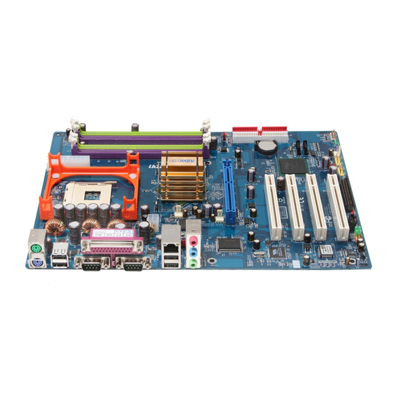
Page 9: Configuration
PX865PEC PRO Configuration Layout of PX865PEC PRO... -
Page 10: Hardware Installation
PX865PEC PRO Hardware Installation This section will assist you in quickly installing your system hardware. Wear a wrist ground strap before handling components. Electrostatic discharge may damage your system components. CPU Processor Installation ® ® This mainboard supports Intel Pentium 4 processors using a Socket 478. -
Page 11: Memory Installation
CPUs that have clock speeds of 100 MHz. It supports DDR266/333 when installed with CPUs that have clock speeds of 133 MHz. And the PX865PEC PRO supports also DDR266/320/400 when installed with CPUs that have CPU clock speeds of 200 MHz. - Page 12 PX865PEC PRO To Enable Dual-Channel DDR, the following conditions must be met: 1.You must use either DIMM1 & DIMM3 together or DIMM2 & DIMM4 together or all four DIMM slots together. 2.You must use matching DIMM configurations between DIMM1 & DIMM3. You must use matching DIMM configurations between DIMM2 &...
-
Page 13: Ram Module Installation
PX865PEC PRO RAM Module Installation: The following instructions explains memory module installation for these mainboards: Pull the white plastic tabs at both ends of the slot away from the slot. Match the notch on the RAM module with the corresponding pattern in the DIMM slot. This will ensure that the module will be inserted with the proper orientation. -
Page 14: Back Panel Configuration
Universal Serial connectors are used to attach to USB devices such as: keyboards, mice and other USB devices. You can plug the USB devices directly into this connector. The PX865PEC PRO also provides a LAN port. You can plug LAN devices directly into this connector. -
Page 15: Audio Port Connectors
PX865PEC PRO Serial and Parallel Interface Ports The mainboard comes equipped with two back panel serial ports and one parallel port. These interface ports will be explained below. Printer Port COM1 COM2 Parallel Interface Port: PRT The parallel port on your system has a 25-pin, DB25 connector and is used to interface with parallel printers and other devices using a parallel interface. -
Page 16: Front Panel Indicator: Sw/Led、Pwrled、Speaker
PX865PEC PRO Front Panel Indicator: SW/LED、PWRLED、SPEAKER HD LED (Hard Drive LED Connector) This connector can be attached to an LED on the front panel of a computer case. The LED will flicker during disk activity. This disk activity only applies to those IDE drives directly attached to the system board. -
Page 17: Connectors
PX865PEC PRO Connectors Floppy Disk Connector: FDC This mainboard provides a standard floppy disk connector (FDC) that supports 360K, 720K, 1.2M, 1.44M and 2.88M floppy diskettes. This connector supports the floppy drive ribbon cables provided in the packaging. Hard Disk Connectors: IDE1-2/ SATA1-2 This mainboard has a 32-bit Enhanced PCI IDE Controller that supports PIO Mode 0~4, Bus Master, Ultra ATA 33/ 66/ 100. -
Page 18: Headers & Jumpers
PX865PEC PRO Headers & Jumpers Front USB Headers: USB3/ USB4 This mainboard provides 2 USB headers on the board allowing for 4 additional USB ports. To make use of these headers, you must attach a USB bracket/cable with USB ports (some models will come packaged with a USB 4-port bracket-cable). - Page 19 PX865PEC PRO Clear CMOS Jumper: JP1 The “Clear CMOS” jumper is used when you cannot boot your system due to some CMOS configuration such as a password that is forgotten. This jumper allows you to reset the CMOS configurations, and then reconfigure.
-
Page 20: Audio Connectors
PX865PEC PRO Audio Connectors This mainboard provides three connectors as part of its audio Subsystem. CD-ROM Audio-In Header: CD-IN This header is used to connect to a CD-ROM / DVD audio cable. S/PDIF (Sony/Philips Digital Interface) Header: SPDIF S/PDIF is a recent audio transfer file format, which provides high quality audio using optical fiber and digital signals. -
Page 21: Slots
PX865PEC PRO SPDIF & FRONT AUDIO bracket (optional) You can connect the bracket to the SPDIF and FRONT AUDIO Headers (This photo can be varied with different models). Slots The slots in this mainboard are designed for expansion cards used to complement and enhance the functionality of the mainboard. -
Page 22: Power Supply Attachments
PX865PEC PRO Power Supply Attachments ATX Power Connector: ATX_12V & ATX_PWR This mainboard requires two ATX power connections; a 20-pin connector and a 4-pin connector, your power supply must have both connectors. Attach the 4-pin connector first then attach the 20-pin... -
Page 23: Chapter 2. Bios Setup
PX865PEC PRO Chapter 2. BIOS Setup Introduction This section describes PHOENIX-AWARD™ BIOS Setup program which resides in the BIOS firmware. The Setup program allows users to modify the basic system configuration. The configuration information is then saved to CMOS RAM where the data is sustained by battery after power-down. -
Page 24: Key Function
PX865PEC PRO DRAM Support DDR (Double Data Rate) SDRAM (Synchronous DRAM) is supported. Supported CPUs ® ® This PHOENIX-AWARD™ BIOS supports the Intel Pentium 4 CPUs. Key Function In general, you can use the arrow keys to highlight items, press <Enter> to select, use the <PgUp>... -
Page 25: Main Menu
PX865PEC PRO Main Menu When you enter the PHOENIX-AWARD™ BIOS Utility, the Main Menu will appear on the screen. The Main menu allows you to select from several configuration options. Use the left/right arrow keys to select a particular configuration screen from the top menu bar or use the down arrow key to access... - Page 26 PX865PEC PRO Main Menu Setup Configuration Options Item Options Description Set the system date. Note that the ‘Day’ automatically Date mm dd yyyy changes when you set the date. Time Hh: mm: ss Set the current time of the system.
-
Page 27: Advanced Bios Features
PX865PEC PRO Advanced BIOS Features Removable Device Priority Select removable device priority. Just like floppy, LS120, ZIP-100, USB-FDD and USB-ZIP. Hard Disk Boot Priority Select hard disk boot priority. CD-ROM Boot Priority Select CD-ROM boot priority. First /Second/Third Boot Device Select the order in which devices will be searched in order to find a boot device. -
Page 28: Cpu Feature
PX865PEC PRO Advanced BIOS Features CPU Feature Delay Prior to Thermal Select the delay time before thermal activation from high temperatures. Options: 4 Min、8 Min、16 Min (default)、32 Min Thermal Management This item will monitor the CPU thermal to prevent the CPU damage with high temperature. -
Page 29: Apic Mode
PX865PEC PRO APIC Mode By enabling this option, “MPS version control for OS” can be configured. Options: Disabled、Enabled (default) MPS Version Control For OS The 1.1 version is the older version that supports 8 more IRQs in the Windows NT environment. -
Page 30: System Bios Cacheable
PX865PEC PRO DRAM RAS# Precharge This item allows you to select the DRAM RAS# precharge time. The ROW address strobe must precharge again before DRAM is refreshed. An inadequate configuration may result in incomplete data. This field is adjustable only when “DRAM Timing Selectable” is set to “manual”. This field is locked when “DRAM Timing Selectable”... -
Page 31: Pci Slot
PX865PEC PRO PCI / VGA Palette Snoop Some graphic controllers that are not VGA compatible take the output from a VGA controller and map it to their display as a way to provide boot information and VGA compatibility. Options: Disabled (default)、Enabled PCI Latency Timer (CLK) This item allows you to set up the PCI Latency Time (0-255). -
Page 32: Spread Spectrum
PX865PEC PRO DDR Speed This item displays the current DDR memory speed. Spread Spectrum The Spread Spectrum function can reduce the EMI (Electromagnetic Interference) generated. Options: Enabled (default)、Disabled AGP/PCI/SRC Speed Setting This item determines the AGP, PCI and SRC frequencies (speed settings). You can set these frequencies using the supplied BIOS options. -
Page 33: Integrated Peripherals
PX865PEC PRO Integrated Peripherals Init Display First With systems that have multiple video cards, this option determines whether the primary display uses a PCI slot or an AGP slot. Options: AGP (default)、PCI Slot OnChip IDE Device IDE HDD Block Mode Block mode is otherwise known as block transfer, multiple commands, or multiple sector read/write. -
Page 34: Onboard Device
PX865PEC PRO IDE Primary / Secondary /Master / Slave UDMA Ultra DMA 100 functionality can be implemented if it is supported by the IDE hard drives in your system. As well, your operating environment requires a DMA driver (Windows 95 OSR2 or a third party IDE bus master driver). -
Page 35: Usb Keyboard Support
PX865PEC PRO USB 2.0 Controller This option should be enabled if your system has a USB 2.0 device installed on the system board. You will need to disable this feature if you install a USB 1.1 device. Options: Enabled (default)、Disabled USB Keyboard Support Enables support for USB attached keyboards. -
Page 36: Onboard Parallel Port
PX865PEC PRO Onboard Serial Port 1/ Port 2 Select an address and corresponding interrupt for the first/ second serial port. Options: Disabled、3F8/IRQ4 (default for port1)、2F8/IRQ3(default for port2)、3E8/IRQ4、 2E8/IRQ3、Auto Onboard Parallel Port Select an address and corresponding interrupt for the onboard parallel port. -
Page 37: Power Management
PX865PEC PRO Power Management The Power Management Setup Menu allows you to configure your system to utilize energy conservation features as well as power-up/ power-down options. ACPI Suspend Type The item allows you to select the suspend type using the ACPI operating system. -
Page 38: Video Off Method
PX865PEC PRO Suspend Mode = 1 minute HDD Power Down = 1 minute 3. User Defined (default) Allows you to set each mode individually. When this option is enabled, each of the ranges are from 1 minute to 1 hour except for HDD Power Down, which ranges from 1 minute to 15 minute and includes a “disable”... - Page 39 PX865PEC PRO Wake Up Control If you highlight the “Wake Up Control” label and then press the enter key, it will display a submenu with the following options: PCI PME Wake Up This option will also cause the system to wake up with any onboard LAN activity.
-
Page 40: Hardware Monitor
PX865PEC PRO Hardware Monitor Smart CPUFAN Temperature This item allows you to choose the CPUFAN temperature. If the CPU temperature is lower then the CPUFAN temperature that you chosen and the CPUFAN will slowdown. Options: Disabled (default)、30 C / 86 F、35... -
Page 41: Load Defaults
PX865PEC PRO Load Defaults Load System Default Settings Load System Default Settings. Load System Turbo Settings Load System Turbo Settings. Load CMOS From BIOS Load defaults from flash ROM for systems without batteries. Save CMOS To BIOS Save defaults to flash ROM for systems without batteries. -
Page 42: Exit Menu
PX865PEC PRO Exit Menu Save & Exit Setup Save all configuration changes to CMOS (memory) and exit setup. A confirmation message will be displayed before proceeding. Exit Without Saving Abandon all changes made during the current session and exit setup. A confirmation message will be... -
Page 43: Chapter 3: Software Setup
PX865PEC PRO Chapter 3: Software Setup Software List Category Platform Intel Chipset INF Windows 98 /ME /2000 /XP VIA LAN Driver Windows 98 /ME /2000 /XP Realtek Audio Driver Windows 98 /ME /2000 /XP Intel USB 2.0 Driver Windows 98 /ME... - Page 44 PX865PEC PRO Intel Chipset INF – provides all the drivers of the functions that built in the Northbridge/ Southbridge VIA LAN Driver – provides driver of VIA 10/100 Ethernet LAN Realtek Audio Driver – provides the driver of Realtek HD Audio Codec Note:You can only install this driver if you are...
-
Page 45: Chapter 4: Troubleshooting
PX865PEC PRO Chapter 4: Troubleshooting Problem 1: No power to the system. Power light does not illuminate. Fan inside power supply does not turn on. Indicator lights on keyboard are not lit. Causes: 1. Power cable is unplugged. 2. Defective power cable. - Page 46 PX865PEC PRO Problem 4: System only boots from the CD-ROM. The hard disk can be read and applications can be used but booting from the hard disk is impossible. Causes: Hard Disk boot sector has been corrupted. Solutions: Back up data and applications files. Reformat the hard drive. Re-install applications and data using backup disks.
- Page 47 PX865PEC PRO Problem 10: Keyboard failure. Causes: Keyboard is disconnected. Solutions: Reconnect keyboard. Replace keyboard if you continue to experience problems. Problem 11: No color on screen. Causes: 1. Faulty Monitor. 2. CMOS incorrectly set up. Solutions: 1. If possible, connect monitor to another system. If no color appears, replace monitor.
-
Page 48: Appendix I: Over Clocking
PX865PEC PRO Appendix I: Over Clocking Important Before you attempt to overclock your system, we strongly recommend that you obtain a thorough understanding of all of the variables, procedures, and the potential risks associated with overclocking. Because we cannot control of all of the possible variables that exist (i.e. memory, AGP card, user configurations, cooling apparatus etc), we cannot assume responsibility from damage to any components of your system due to overclocking. -
Page 49: Cpu Clock Ratio
PX865PEC PRO How to configure your new frequencies. As mentioned you must enter the BIOS Setup Utility in order to begin configuring overclocking parameters. After you reboot your system, press the “Del” key when prompted to enter the BIOS Setup Utility. The parameters for overclocking will be found in the “Advanced” screen as part of the “Frequency/Voltage Control”... - Page 50 PX865PEC PRO AGP/PCI/SRC Speed Setting This item determines the AGP, PCI and SRC frequencies (speed settings). You can set these frequencies using the supplied BIOS options. One of the options available to you is “Auto, Auto, Auto”. Using the “Auto, Auto, Auto” option will instruct the system to automatically calculate these frequencies based on the factory default “CPU Host Frequency”...
- Page 51 PX865PEC PRO Testing Even though you have configured your overclocking options and have successfully booted to your operating system, it doesn’t mean that you have successfully overclocked your system. Testing is an equally important aspect of overclocking and you must stress your configurations thoroughly to ensure stability.
- Page 52 PX865PEC PRO Example: This example shows you how to overclock the CPU Internal Clock, DDR frequency and FSB frequency for an Intel based mainboard. Note that the options that are supplied with your version of the BIOS may vary slightly. The example is for reference only.
-
Page 53: Appendix Ii: Super 5.1 Channel Setup
PX865PEC PRO Appendix II: Super 5.1 Channel Setup 1. After getting into the system, click the audio icon from the Windows screen. 2. Click Speaker Configuration button, you can see the screen like the picture below. 3. You can choose 2, 4 or 6 channels by your speakers. -
Page 54: Appendix Iii: How To Install Windows ® 98/ Me To The Sata Device
PX865PEC PRO ® Appendix III: How to install Windows 98/ ME to the SATA device? Please follow the steps below : 1. Make sure that the “On-Chip Serial ATA” option is set to “ Combined Mode” in the BIOS Setup Utility.
Need help?
Do you have a question about the PX865PEC PRO and is the answer not in the manual?
Questions and answers