Table of Contents
Advertisement
Advertisement
Table of Contents

Related Manuals for Blodgett Combi Manual Control BCM


Summary of Contents for Blodgett Combi Manual Control BCM
-
Page 1: Wire Schematic_Diagram
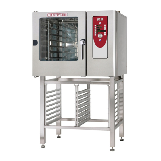
Service & Installation Manual For BCM Electric Oven “Manual Control”... -
Page 2: Table Of Contents
Table of Contents Data Plate Installation and connection -Water connection -Drain connection -Electrical connection/survey of supply lines Start Menu Oven set-up Set –up Mode U 9-10 Test Mode Test Mode D0-D6 Test Mode D7-D15 Test Mode D16-D20 Test Mode D21-D28 User Menu User Menu B1-B7 User Menu B8-B13... -
Page 3: Data Plate
Installation and Connections Data Plate When communicating with BLODGETT, we kindly ask you inform us of the serial number of the oven that is stated on the approval plate. The approval plate is located on the right-hand corner post of the oven cabinet, as shown below. -
Page 4: Cooling Down / Preheat Operation
Water Connections BLODGETT ovens have one or two water connections. Two is most common. To facilitate cleaning and service, the oven should be connected with an approved flexible ¾” hose and the permanent installations should be fitted with a stop-tap and a non-return valve. Before connecting the oven to water, flush the tubes thoroughly. -
Page 5: Installation And Connection
Installation and Connection Drain connection From the factory, the BLODGETT ovens are equipped with a drain system that removes surplus water from the oven chamber. This water may be condensed water from the products, or it may occur when the oven chamber is cooled down with cold water, or when the oven chamber is cleaned. Connection must be carried out by a license plumber, to an open or to a closed drain. - Page 6 Checking before Use The oven should be checked before you start using it. On the outside Check that the oven has not been damaged in transit (dents, scratches, etc.) • Check/adjust the height and check that the oven is placed level (horizontally) •...
-
Page 7: Start Menu
Start Menu Power Switch Change oven HOT AIR selected if temperature with control lamp on turn switch COMBI STEAMING selected if upper or Change time with middle control lamp turn switch is on. REHEATING is selected if lower control lamp is on Core temperature on C and K models. -
Page 8: Oven Set-Up
Oven set-up Power Switch Display shows Press HOT AIR and setting STEAMING for 2 sec. Not active Possible to change to "d" test mode with combi steam key Display shows "U" Press STEAMING/ PREHEATING and HOT AIR for 2 sec. Display shows Not active description of "U"... -
Page 9: Set-Up Mode U
Set-up Mode U In the set-up function, it is possible to set the oven controller to match the mechanical set-up and the choice of software. If the set-up has been changed in U1, U4 or U15, the oven will be reset. U1 Oven model You select the oven model (B, C or K) by pressing the step key. - Page 10 U10 Programs You activate the program mode by pressing the step key. 0= OFF, 1= 10 programs with 3 process steps. NOTE: It is still possible to activate the cleaning program even though the program mode is not active. 0= OFF. U11 Core temperature probe You activate and deactivate the core temperature probe by pressing the step key.
-
Page 11: Test Mode
Test Mode Power Switch Display shows For test mode, press setting HOT AIR and COMBI STEAMING for 2 sec. Display shows For test mode, press setting COMBI STEAMING and HOT AIR for 2 sec. Display shows "d" Possible to change to "U"... -
Page 12: Test Mode D0-D6
Test Mode D0-D6 In the test mode, it is possible to activate all electrical components. This is very useful in connection with fault detection and the testing and adjusting of replacement parts. D0 Main contactor(s) This function activates contactor K1. You activate or deactivate the function by pressing the step key. -
Page 13: Test Mode D7-D15
Test Mode D7-D15 D7 Filling valve Available on K models only. This function activates solenoid valve MV2. You activate or deactivate the function by pressing the step key. To pulse, press the alarm key. 0= OFF, 1= ON. D8 Drain pump Available on K models only. -
Page 14: Test Mode D16-D20
Test Mode D16-D20 D16 Core temperature This function is not available on B models. C and K models can use only one core temperature probe, it is possible, however, to test core temperature probes 1 and 2. Here it is possible to read the current temperature of the core temperature sensor, P2 + P2A. In the field next to ”Temperature”, the current temperature is shown. - Page 15 Test Functions D21-28 D21 Water level Available on K models only. Here it is possible to read the status of SE2. In the display next to ”Time”, the conductivity is shown and it is indicated whether the water level is high or low XX|LO= low water level, XX|HI= high water level.
-
Page 16: Test Mode D29-D47
Test Mode D29-D47 D29 CombiWash water Only possible on ovens with CombiWash. This function activates solenoid valve MV4. You activate or deactivate the function by pressing the step key. To pulse, press the alarm key. 0= OFF, 1= ON. D34 Water pressure sensor Here it is possible to read the status of P7. -
Page 17: User Menu
User Menu Main switch Display shows Not active setting Display shows Not active setting Display shows "b" Not active Display shows Not active description of "b" function Display shows Not active setting Press key for 5 sec. Turn switch to access user menu Start/Stop To enter user menu, press alarm key for 5 sec. -
Page 18: User Menu B1-B7
User Menu B1-B7 B1 Save pre-settings In this function, you save the preset time and temperature. If, for instance, the end user uses HOT AIR at 180°C for 30 minutes, the standard setting can be changed as follows: 1. Change time and temperature. 2. -
Page 19: User Menu B8-B13
User Menu B8-B13 B8 Exhaust In this function, you choose whether the oven should start up the extraction hood. 0= Extraction hood not controlled by oven 1= Extraction hood runs for 10 minutes after oven has stopped. This applies to an extraction hood mounted on the oven as well as for an external extraction hood. B9 Time graphics In this function, you determine whether the oven should be able to show graphically how long time has passed of a cooking sequence. -
Page 20: User Menu B14-B21
User Menu B14-B21 B14 year In this function, you set the year. 1. Press the key next to the temperature display (digit flashes). 2. Turn the switch to the desired setting. 3. Press the key next to the temperature display (digit stops flashing). You set the year from 6 to 20. -
Page 21: User Menu B22-B24
User Menu B22-B24 B22 Screen saver In this function, you set the time that should pass until the clock appears in the display. Press step key to select time. 0= no screen saver 1= 10 sec. 2= 30 sec. 3= 60 sec. 4= 180 sec. -
Page 22: Error Codes
Error codes Main switch Display shows error "Er" No Display shows description of error Turn switch Start/Stop All keys can be used to acknowledge an error message. -
Page 23: Error Code List
Error codes Generator too hot (Generator thermo switch has tripped. Reconnect Error code 3: GENRA HOT by pressing button under oven.) Oven too hot (Oven chamber thermo switch has tripped. Reconnect Error code 4: OVEN HOT by pressing button under oven.) Fan too hot (Thermo switch in motor has tripped. -
Page 24: Notes
Notes: ________________________________________________________________________ ________________________________________________________________________ ________________________________________________________________________ ________________________________________________________________________ ________________________________________________________________________ ________________________________________________________________________ ________________________________________________________________________ ________________________________________________________________________ ________________________________________________________________________ ________________________________________________________________________ ________________________________________________________________________ ________________________________________________________________________ ________________________________________________________________________ ________________________________________________________________________ ________________________________________________________________________ ________________________________________________________________________ ________________________________________________________________________ ________________________________________________________________________ ________________________________________________________________________ ________________________________________________________________________ ________________________________________________________________________ ________________________________________________________________________ ________________________________________________________________________ ________________________________________________________________________ ________________________________________________________________________ ________________________________________________________________________ ________________________________________________________________________ ________________________________________________________________________... - Page 25 BCP & BCM , ERROR CODES & CAUSES - Generator Hot – Generator High Limit Thermostat Open(Opens at 275˚F) (Manual Reset under a cover at the bottom of the control panel) – Oven Hot - Oven High Limit Thermostat Open (Opens at 662˚F) (Manual Reset under a cover at the bottom of the control panel) –...
- Page 26 BCP & BCM , ERROR CODES & CAUSES – Main Alarm Error –No 24V signal to high limit board – Door Sensor Error – Wrong door sensor signal – Water Pressure Low – Water Pressure Switch (located on the larger solenoid assembly) is closed. (Opens at 22 PSI) –...
-
Page 27: Sequence Of Operation
BLODGETT OVEN COMBI Sequence of Operation for BCP and BCM (electric) Unit is turned “OFF” You will have AC voltage at: • The bottom of the main contactor (T1, T2, T3) • Fuse F5 in the front • The transformer (T1) in the front of the oven •... - Page 28 BLODGETT OVEN COMBI Unit set in “Hot air” Max temperature 250°C/482°F • The SSR gets DC voltage on the terminal -/+1 (if boiler model) -/+1 and 2 (if no boiler) DC coming from J2 pin 22 and 23. • The IO board will get a resistance input from P1 (oven temperature sensor PT100) on J1 pin 37 and 38 telling the IO board when to switch off the SSR.
- Page 29 BLODGETT OVEN COMBI Unit set in “Steam” Max temperature 100°C/212°F, Forced steam 120°C/348°F • If P3 (temperature sensor of boiler PT100) register an Ohm value which is higher than 65°C/149°F it will start filling to HIGH level. If the value is lower than 65°C/149°F empty and flush the boiler as described below.
- Page 30 BLODGETT OVEN COMBI Unit set in “Proving” (Only BCP) • Standard fan speed 50% (5 VDC on inverter terminal Com and Speed, IO board J2 pin 33 and 34) • As standard inject water every 20 sec. for 1 sec. through MV1 (injection valve) 24 VAC (IO board J2 pin 8) •...
- Page 31 9. maj 2011 9. maj 2011 HOUNÖ A/S HOUNÖ A/S Dias 5 Dias 5 Front side B, C, K controller Power Keyboard 3.3V Testpins 24V AC Start IO Programming connector reset Short Short flash at start-up Com IO light diodes: Yellow transmit Green receive Must flash...
- Page 32 9. maj 2011 9. maj 2011 HOUNÖ A/S HOUNÖ A/S Dias 6 Dias 6 Back side B, C, K controler Keyboard Memory key connector Programming connector Buzzer Buzzer Battery (3V) Power: Power: 1,2 - - COM IO COM IO 3 3 - - GND 4 4 - - Start IO Start IO RS232...
- Page 33 BCP / BCM Water Level Switch BCP / BCM Water Level Switch Test Points Sensor Power 12 VDC Empty 1.2 VDC Full 0 VDC Wire Side Sensor Side 24Vdc- Delime Pump Black 24Vdc+ Delime Pump Red ------- Not used 130 Q1 High Limit stat Motor “G”...
-
Page 34: Bcm Start Up Guide
When pump has been primed, press the Stage key press the Stage key once to 0 the pump will deactivate. Press and hold the Hot Air & Combi Keys for 2-3 seconds. BCM Blodgett Combi Oven Page 1... - Page 43 9. maj 2011 9. maj 2011 HOUNÖ A/S HOUNÖ A/S Dias 2 Dias 2 Wiring diagram: Page 1 High limit High limit circuit board Supply CombiWash pump, vent. Output Com. to CPU Input Input to IO board Oven light To high limit components Cooling fan, empty pump...
- Page 44 9. maj 2011 9. maj 2011 HOUNÖ A/S HOUNÖ A/S Dias 3 Dias 3 Wiring diagram: Page 2 Solid state Solid state relay no. 1 relay no. 2 Main contactor Main fuse for transformer fase Please note this is only for C - CPE Main fuse for transformer...
- Page 45 9. maj 2011 9. maj 2011 HOUNÖ A/S HOUNÖ A/S Dias 4 Dias 4 Wiring diagram: Page 3 Please note this is only for K - KPE Solid state Solid state Solid state Solid state relay no. 1 relay no. 4 relay no.
- Page 46 9. maj 2011 9. maj 2011 HOUNÖ A/S HOUNÖ A/S Dias 5 Dias 5 Wiring diagram: Page 4 Connection to main fuse F5 Terminals on main contactor Transformer Connection to neutral terminal Fuse for IO and CPU board Frequency Fuse for all Fuse for inverter 24V output...
- Page 47 9. maj 2011 9. maj 2011 HOUNÖ A/S HOUNÖ A/S Dias 6 Dias 6 Wiring diagram: Page 5 Core probe Oven temp. Core probe Doorsensor Sensor for temp. sensor 1 sensor temp. sensor 2 singel door ClimaOptima Plug on Alarm sens print Temp.
- Page 48 9. maj 2011 9. maj 2011 HOUNÖ A/S HOUNÖ A/S Dias 7 Dias 7 Wiring diagram: Page 6 Solenoid valve filling boiler Lamp in restart Solenoid valve Coil main button contactor CombiWash High limit Connections to solid Plug on alarm Connections to SSR if more stat relay...
- Page 49 9. maj 2011 9. maj 2011 HOUNÖ A/S HOUNÖ A/S Dias 8 Dias 8 Wiring diagram: Page 7 Connection to terminal 2 (ext. vent) Connection to Fuse F5 Connection to Connection to Fuse F5 Fuse F3 Connection to Fuse F3 Rinse pump Empty pump boiler...
Need help?
Do you have a question about the Manual Control BCM and is the answer not in the manual?
Questions and answers