Table of Contents
Advertisement
Quick Links
Download this manual
See also:
Manual
Advertisement
Table of Contents

Related Manuals for VIPA System 300S


Summary of Contents for VIPA System 300S
- Page 1 VIPA System 300S SM-AIO | | Manual HB140 | SM-AIO | | GB | Rev. 16-39 Analog signal modules - SM 33x(S)
- Page 2 VIPA GmbH Ohmstr. 4 91074 Herzogenaurach Telephone: 09132-744-0 Fax: 09132-744-1864 Email: info@vipa.com Internet: www.vipa.com 300S_SM-AIO,4,GB - © 2016...
-
Page 3: Table Of Contents
VIPA System 300S Table of contents Table of contents Basics..................5 1.1 Copyright © VIPA GmbH ........... 5 1.2 Über dieses Handbuch............6 1.3 Safety information.............. 7 Assembly and installation guidelines........9 2.1 Safety information for users..........9 2.2 Overview................9 2.3 Installation dimensions............. - Page 4 Table of contents VIPA System 300S 4.9.1 Manual operation............111 4.9.2 Technical data.............. 112 Analog I/O Modules.............. 115 5.1 General................115 5.2 Analog value representation........... 115 5.3 Parameterization............118 5.3.1 Parameterization by hardware configuration....118 5.3.2 Parameterization during run time by means of SFCs.. 119 5.4 334-0KE00 - AI 4/AO 2x12Bit ........
-
Page 5: Basics
Basics 1.1 Copyright © VIPA GmbH All Rights Reserved This document contains proprietary information of VIPA and is not to be disclosed or used except in accordance with applicable agree- ments. This material is protected by the copyright laws. It may not be repro-... -
Page 6: Über Dieses Handbuch
Basics VIPA System 300S Über dieses Handbuch Trademarks VIPA, SLIO, System 100V, System 200V, System 300V, System 300S, System 400V, System 500S and Commander Compact are registered trademarks of VIPA Gesellschaft für Visualisierung und Prozessautomatisierung mbH. SPEED7 is a registered trademark of profichip GmbH. -
Page 7: Safety Information
VIPA System 300S Basics Safety information Availability The manual is available in: printed form, on paper in electronic form as PDF-file (Adobe Acrobat Reader) Icons Headings Important passages in the text are highlighted by following icons and headings: DANGER! Immediate or likely danger. Personal injury is possible. - Page 8 Basics VIPA System 300S Safety information CAUTION! The following conditions must be met before using or commissioning the components described in this manual: – Hardware modifications to the process control system should only be carried out when the system has been disconnected from power! –...
-
Page 9: Assembly And Installation Guidelines
While the standard peripheral modules are plugged-in at the right side of the CPU, the SPEED-Bus peripheral modules are connected via a SPEED-Bus bus connector at the left side of the CPU. VIPA delivers profile rails with integrated SPEED-Bus for 2, 6 or 10 SPEED-Bus peripheral modules with different lengths. -
Page 10: Installation Dimensions
Assembly and installation guidelines VIPA System 300S Installation dimensions Serial Standard bus The single modules are directly installed on a profile rail and con- nected via the backplane bus coupler. Before installing the modules you have to clip the backplane bus coupler to the module from the backside. - Page 11 VIPA System 300S Assembly and installation guidelines Installation dimensions Dimensions Installation dimensions HB140 | SM-AIO | | GB | Rev. 16-39...
-
Page 12: Assembly Speed-Bus
Assembly and installation guidelines VIPA System 300S Assembly SPEED-Bus 2.4 Assembly SPEED-Bus Pre-manufactured For the deployment of SPEED-Bus modules, a pre-manufactured SPEED-Bus profile rail SPEED-Bus rail is required. This is available mounted on a profile rail with 2, 6 or 10 extension slots. - Page 13 VIPA System 300S Assembly and installation guidelines Assembly SPEED-Bus Installation of the pro- Bolt the profile rail with the background (screw size: M6), so that file rail you still have minimum 65mm space above and 40mm below the profile rail. Please look for a low-impedance connection between profile rail and background.
- Page 14 Assembly and installation guidelines VIPA System 300S Assembly SPEED-Bus To connect the SPEED-Bus modules, plug it between the trian- gular positioning helps to a slot marked with "SLOT ..." and pull it down. Only the "SLOT1 DCDC" allows you to plug-in either a SPEED- Bus module or an additional power supply.
-
Page 15: Assembly Standard Bus
VIPA System 300S Assembly and installation guidelines Assembly standard bus CAUTION! – The power supplies must be released before instal- lation and repair tasks, i.e. before handling with the power supply or with the cabling you must discon- nect current/voltage (pull plug, at fixed connection switch off the concerning fuse)! –... - Page 16 VIPA System 300S Assembly standard bus Bus connector For the communication between the modules the System 300S uses a backplane bus connector. Backplane bus connectors are included in the delivering of the peripheral modules and are clipped at the module from the backside before installing it to the profile rail.
-
Page 17: Cabling
VIPA System 300S Assembly and installation guidelines Cabling Click the CPU downwards and bolt it like shown. 10. Repeat this procedure with the peripheral modules, by clicking a backplane bus connector, stick the module right from the mod- ules you've already fixed, click it downwards and connect it with the backplane bus connector of the last module and bolt it. - Page 18 Assembly and installation guidelines VIPA System 300S Cabling CageClamp technology For the cabling of power supply of a CPU, a green plug with Cage- (green) Clamp technology is deployed. The connection clamp is realized as plug that may be clipped off carefully if it is still cabled.
- Page 19 VIPA System 300S Assembly and installation guidelines Cabling 20pole screw connec- tion 392-1AJ00 Open the front flap of your I/O module. Bring the front connector in cabling position. For this you plug the front connector on the module until it locks.
-
Page 20: Installation Guidelines
Assembly and installation guidelines VIPA System 300S Installation guidelines 40pole screw connec- tion 392-1AM00 Open the front flap of your I/O module. Bring the front connector in cabling position. For this you plug the front connector on the module until it locks. - Page 21 The components of VIPA are developed for the deployment in indus- trial environments and meets high demands on the EMC. Neverthe- less you should project an EMC planning before installing the compo- nents and take conceivable interference causes into account.
- Page 22 Assembly and installation guidelines VIPA System 300S Installation guidelines Proof the correct fixing of the lead isolation. – Data lines must be laid isolated. – Analog lines must be laid isolated. When transmitting signals with small amplitudes the one sided laying of the isolation may be favourable.
-
Page 23: General Data I/O Modules
VIPA System 300S Assembly and installation guidelines General data I/O modules > General data To fix the isolation tangles use cable clamps out of metal. The clamps must clasp the isolation extensively and have well contact. Lay the isolation on an isolation rail directly after the entry of the cable in the cabinet. - Page 24 Assembly and installation guidelines VIPA System 300S General data I/O modules > General data Protection of persons and device protection to the field bus electrically isolated to the process level electrically isolated Insulation resistance Insulation voltage to reference earth Inputs / outputs...
- Page 25 VIPA System 300S Assembly and installation guidelines General data I/O modules > General data Standard Comment EN 61000-4-3 HF field immunity (casing) 80MHz … 1000MHz, 10V/m, 80% AM (1kHz) 1.4GHz ... 2.0GHz, 3V/m, 80% AM (1kHz) 2GHz ... 2.7GHz, 1V/m, 80% AM (1kHz)
-
Page 26: Analog Input Modules
Parameterization The analog input modules from VIPA do not have any measuring range plug. The modules are parameterized via the hardware config- urator or during runtime via SFCs. -
Page 27: Parameterization - Basics
Configure your CPU. Link-up your System 300 modules in the plugged-in sequence starting with slot 4. Here the analog input modules of VIPA are to be projected as analog input modules of Siemens: ð The analog input modules can be found at the hardware cat- alog at SIMATIC 300 >... - Page 28 Analog Input Modules VIPA System 300S Parameterization - Basics > Parameterization during runtime busy BOOL Set Record set 1: L B#16#0 //Diagnostic disabled T #rec1[0] L B#16#AA //Interference freq. suppression T #rec1[1] L B#16#D4 //Meas. range Type S: 0100b T #rec1[2] //Meas. type: Thermocouple...
- Page 29 VIPA System 300S Analog Input Modules Parameterization - Basics > Parameterization during runtime Byte Bit 7 ... Bit 0 Mode Channel 6/7 Bit 3 ... 0: Measuring range Bit 7 ... 4: Measuring type 6, 7 Upper limit value Channel 0...
-
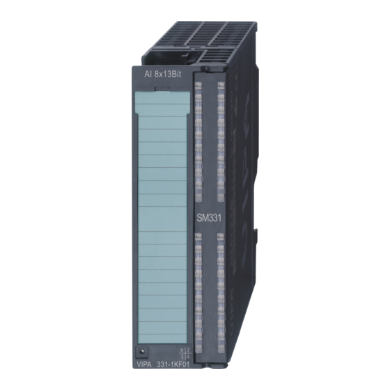
Page 30: 331-1Kf01 - Ai 8X13Bit
Analog Input Modules VIPA System 300S 331-1KF01 - AI 8x13Bit For the module 331-7Kx01 results from the table in the case of "Ther- mocouple with compensation internal, linear" the binary coding for measuring type: 1101b. For Measuring range "Type S" the binary measuring range coding results as: 0100b. - Page 31 VIPA System 300S Analog Input Modules 331-1KF01 - AI 8x13Bit Structure 1 LEDs (not active) 2 flap with labeling strip 3 contact bar 4 flap opened with inner label HB140 | SM-AIO | | GB | Rev. 16-39...
- Page 32 Analog Input Modules VIPA System 300S 331-1KF01 - AI 8x13Bit Pin assignment Assignment Connection U+ channel 0 I+ channel 0 S- channel 0 M+ channel 0 M- channel 0 U+ channel 1 I+ channel 1 S- channel 1 M+ channel 1...
- Page 33 VIPA System 300S Analog Input Modules 331-1KF01 - AI 8x13Bit Assignment Connection M+ channel 7 M- channel 7 Wiring diagrams The following illustration shows the connection options for the dif- ferent measuring ranges. The assignment to the measuring ranges is to find in the column "Conn."...
-
Page 34: 331-1Kf01 - Ai 8X13Bit - Parameterization
Analog Input Modules VIPA System 300S 331-1KF01 - AI 8x13Bit > 331-1KF01 - AI 8x13Bit - Parameterization Resolu- Analog value tion High-Byte Low-Byte Bit number Value 12bit + Measuring value sign 3.3.1 331-1KF01 - AI 8x13Bit - Parameterization Overview After Power ON the module is set to ±10V for all channels with an integration time of 60ms. - Page 35 VIPA System 300S Analog Input Modules 331-1KF01 - AI 8x13Bit > 331-1KF01 - AI 8x13Bit - Parameterization Record set 1 (Byte 0 to 13): Byte Bit 7 ... Bit 0 Temperature measuring: 0000 0000b: Grad Celsius 0000 1000b: Grad Fahrenheit...
- Page 36 Analog Input Modules VIPA System 300S 331-1KF01 - AI 8x13Bit > 331-1KF01 - AI 8x13Bit - Parameterization Byte Bit 7 ... Bit 0 Temperature coefficient:: Bit 3 ... 0: channel 5 Bit 7 ... 4: channel 4 Temperature coefficient:: Bit 3 ... 0: channel 7 Bit 7 ...
- Page 37 VIPA System 300S Analog Input Modules 331-1KF01 - AI 8x13Bit > 331-1KF01 - AI 8x13Bit - Parameterization Measuring Measuring range / Representation Measuring range range coding (Connection) +/- 1V 1.176V = End overdrive region (32511) 0100b (Connection 3) - 1...1V = Nominal range (-27648...27648) - 1.175V= End underdrive region (-32512)
- Page 38 Analog Input Modules VIPA System 300S 331-1KF01 - AI 8x13Bit > 331-1KF01 - AI 8x13Bit - Parameterization 3.3.1.2.3 Measuring type Resistance measuring Measuring type coding: 0101b Measuring Measuring range / Representation Measuring range range coding (Connection) 600 Ohm 705.53 Ohm = End overdrive region (32511) 0010b (Connect.
- Page 39 VIPA System 300S Analog Input Modules 331-1KF01 - AI 8x13Bit > 331-1KF01 - AI 8x13Bit - Parameterization Meas. °C Unit °F Unit Unit Range Range range (0.1°C/ (0.1°F/ (0.1K/ coding digit) digit) digit) 295.0 2950 563.0 5630 568.2 5682 Ni100...
-
Page 40: 331-1Kf01 - Technical Data
Analog Input Modules VIPA System 300S 331-1KF01 - AI 8x13Bit > 331-1KF01 - Technical data Meas. °C Unit °F Unit Unit Range Range range (0.1°C/ (0.1°F/ (0.1K/ coding digit) digit) digit) 250.00 25000 280.00 28000 Nominal range -60.00 -6000 -76.00 7600 -105.00... - Page 41 VIPA System 300S Analog Input Modules 331-1KF01 - AI 8x13Bit > 331-1KF01 - Technical data Order no. 331-1KF01 Cable length, shielded 50 m Rated load voltage Current consumption from load voltage L+ (without load) Voltage inputs ü Min. input resistance (voltage range) 100 kΩ...
- Page 42 Analog Input Modules VIPA System 300S 331-1KF01 - AI 8x13Bit > 331-1KF01 - Technical data Order no. 331-1KF01 Basic error limit +/-0.3% Basic error limit with SFU Destruction limit resistance inputs max. 15V Resistance thermometer inputs ü Resistance thermometer ranges...
- Page 43 VIPA System 300S Analog Input Modules 331-1KF01 - AI 8x13Bit > 331-1KF01 - Technical data Order no. 331-1KF01 Interrupts Process alarm Diagnostic interrupt Diagnostic functions Diagnostics information read-out none Supply voltage display none Group error display none Channel error display...
- Page 44 Analog Input Modules VIPA System 300S 331-1KF01 - AI 8x13Bit > 331-1KF01 - Technical data Order no. 331-1KF01 Environmental conditions Operating temperature 0 °C to 60 °C Storage temperature -25 °C to 70 °C Certifications UL certification KC certification Additional Technical data...
-
Page 45: 331-7Kx01 - Ai 8(2)X12Bit
VIPA System 300S Analog Input Modules 331-7Kx01 - AI 8(2)x12Bit Order number 331-1KF01 ±5V, 1...5V, ±10V, 100kW 0...10V - Current ±20mA, 0...20mA, 100W 4...20mA - Resistors 0 ... 600W, 0 ... 6kW 100MW - Resistance thermometer Pt100 Standard / Cli-... - Page 46 Analog Input Modules VIPA System 300S 331-7Kx01 - AI 8(2)x12Bit Properties The analog input modules transform analog signals from the process into digital signals for the internal processing. The modules are pin and function compatible to the modules from Siemens with the same name.
- Page 47 VIPA System 300S Analog Input Modules 331-7Kx01 - AI 8(2)x12Bit Pin assignment 331-7KF01 Assignment Connection 331-7KF01 Description Power supply LED (red) DC 24V Group error, ON as soon as + Channel 0 a diagnostic entry is present Ground respectively Channel 0...
-
Page 48: Connection Of Sensors
Analog Input Modules VIPA System 300S 331-7Kx01 - AI 8(2)x12Bit > Connection of sensors Pin assignment LED 331-7KB01 Assignment Connection 331-7KB01 Description Power supply LED (red) DC 24V Group error, ON as soon as + Channel 0 a diagnostic entry is present... - Page 49 VIPA System 300S Analog Input Modules 331-7Kx01 - AI 8(2)x12Bit > Connection of sensors The 2wire measuring transducer gets the supply voltage (13V at 30mA) short-circuit resistant via the clamps of the analog input module. The 2wire measuring transducer transduces the measuring value into a current.
- Page 50 Analog Input Modules VIPA System 300S 331-7Kx01 - AI 8(2)x12Bit > Connection of sensors Operating basics Independent from the type of the thermocouple the principle of meas- uring is identical for all types: When the measuring point has another temperature than the free ends of the thermo pair (connection point), a voltage occurs between the free ends, the thermo voltage.
- Page 51 VIPA System 300S Analog Input Modules 331-7Kx01 - AI 8(2)x12Bit > Connection of sensors Installation of resist- The installation of resistance thermometers/resistors needs 4wires. ance thermometers and Via the connections I and I the resistance thermometer/resistor resistors gets a constant current. The voltage occurring at the resistor ther- mometer/resistor is measured via the connections M+ and M-.
- Page 52 Analog Input Modules VIPA System 300S 331-7Kx01 - AI 8(2)x12Bit > Connection of sensors M+: measuring line (positive) M-: measuring line (negative) : constant current line (positive) : constant current line (negative) *) With a wire break at the Pt100 reference junction for evaluation, the 1. channel of one group shows the value 7FFFh.
-
Page 53: 331-7Kx01 - Ai 8(2)X12Bit - Parameterization
VIPA System 300S Analog Input Modules 331-7Kx01 - AI 8(2)x12Bit > 331-7Kx01 - AI 8(2)x12Bit - Parameterization Resolution The resolution of an analog value is 14bit plus sign bit. Bit 15 serves as sign bit (SG) with the meaning: For the sign bit is valid: Bit 15 = "0"... - Page 54 Analog Input Modules VIPA System 300S 331-7Kx01 - AI 8(2)x12Bit > 331-7Kx01 - AI 8(2)x12Bit - Parameterization Install module Start the hardware configurator and load your project for the analog module. Open the hardware catalog to install the analog input module. In the hardware catalog the analog modules with the order-no.:...
- Page 55 VIPA System 300S Analog Input Modules 331-7Kx01 - AI 8(2)x12Bit > 331-7Kx01 - AI 8(2)x12Bit - Parameterization Record set 0 (Byte 0 to 1): Byte Bit 7 ... Bit 0 Default Group diagnosis bit coded Bit 0: Channel 0/1 Bit 1: Channel 2/3...
- Page 56 Analog Input Modules VIPA System 300S 331-7Kx01 - AI 8(2)x12Bit > 331-7Kx01 - AI 8(2)x12Bit - Parameterization Byte Bit 7 ... Bit 0 Default 8, 9 Lower limit value Channel 0 8000h 10, 11 Upper limit value Channel 2 7FFFh...
- Page 57 VIPA System 300S Analog Input Modules 331-7Kx01 - AI 8(2)x12Bit > 331-7Kx01 - AI 8(2)x12Bit - Parameterization Measuring Range / Representation Range range coding +/- 2.5V 2.939V = End overdrive region (32511) 0101b - 2.5...2.5V = Nominal range (-27648...27648) - 2.933V = End underdrive region (-32512) +/- 5V 5.879V = End overdrive region (32511)
- Page 58 Analog Input Modules VIPA System 300S 331-7Kx01 - AI 8(2)x12Bit > 331-7Kx01 - AI 8(2)x12Bit - Parameterization 2wire Current measuring (Measuring type coding: 0011b) Measuring Range / Representation Range range coding 4...20mA 22.810mA = End overdrive region (32511) 0011b 4...20mA = Nominal range (0...27648) 1.185mA = End underdrive region (-4864)
- Page 59 VIPA System 300S Analog Input Modules 331-7Kx01 - AI 8(2)x12Bit > 331-7Kx01 - AI 8(2)x12Bit - Parameterization Measuring Range / Representation Range range coding Pt 100 1000 = End overdrive region (10000) 1101b reference -100...200 = Nominal range (-1000...2000) junction -243 = End underdrive region (-2430) (0.1°C/digit)
- Page 60 Analog Input Modules VIPA System 300S 331-7Kx01 - AI 8(2)x12Bit > 331-7Kx01 - AI 8(2)x12Bit - Parameterization Measuring Range / Representation in °C (0.1°C/digit) Range range coding Type L 1150 = End overdrive region (11500) 0110b [Fe-Cu-Ni] -200...900 = Nominal range (-2000...9000)
-
Page 61: 331-7Kx01 - Ai 8(2)X12Bit - Diagnostics
VIPA System 300S Analog Input Modules 331-7Kx01 - AI 8(2)x12Bit > 331-7Kx01 - AI 8(2)x12Bit - Diagnostics Measuring Range / Representation Range range coding Type C 1010b [WRe5-WRe26] *1) The measuring range is available starting with firmware version V. 1.3.8. Since this measuring range is not supported by the Siemens SIMATIC manager, the parameterization only takes place exclusively at run time. - Page 62 Analog Input Modules VIPA System 300S 331-7Kx01 - AI 8(2)x12Bit > 331-7Kx01 - AI 8(2)x12Bit - Diagnostics Evaluating the diag- At a diagnosis event the CPU interrupts the user program and nosis branches into OB 82. This OB allows you via according programming to request detailed diagnostic information by means of the SFCs 51 and 59 and react to it.
- Page 63 VIPA System 300S Analog Input Modules 331-7Kx01 - AI 8(2)x12Bit > 331-7Kx01 - AI 8(2)x12Bit - Diagnostics Record set 1 (Byte 0 to 15): Byte Bit 7 ... Bit 0 Default 0 ... 3 Content record set 0 (see page before) Bit 6 ...
- Page 64 Analog Input Modules VIPA System 300S 331-7Kx01 - AI 8(2)x12Bit > 331-7Kx01 - AI 8(2)x12Bit - Diagnostics Message Possible error cause Remedial Project engineering/ Parameterization at run time: Proof the parameterization during run time Parameterization error Wrong function code in record set...
- Page 65 VIPA System 300S Analog Input Modules 331-7Kx01 - AI 8(2)x12Bit > 331-7Kx01 - AI 8(2)x12Bit - Diagnostics Initializing the process As soon as a measuring value is out of the range defined in the interrupt parameterization, a processes interrupt is initialized, if this option is released.
-
Page 66: 331-7Kb01 - Technical Data
Analog Input Modules VIPA System 300S 331-7Kx01 - AI 8(2)x12Bit > 331-7KB01 - Technical data Diagnostic message If a second identical process interrupt occurs during processing inter- "Process interrupt lost" rupt in OB 40, the CPU branches into the OB 82 and activates the bit 6 in record set 0 of byte 3 for "process interrupt lost". - Page 67 VIPA System 300S Analog Input Modules 331-7Kx01 - AI 8(2)x12Bit > 331-7KB01 - Technical data Order no. 331-7KB01 Min. input resistance (voltage range) 100 kΩ Input voltage ranges -80 mV ... +80 mV -250 mV ... +250 mV -500 mV ... +500 mV -1 V ...
- Page 68 Analog Input Modules VIPA System 300S 331-7Kx01 - AI 8(2)x12Bit > 331-7KB01 - Technical data Order no. 331-7KB01 Basic error limit with SFU Destruction limit resistance inputs max. 15V Resistance thermometer inputs ü Resistance thermometer ranges Pt100 Ni100 Operational limit of resistance thermometer +/-0.7% ...
- Page 69 VIPA System 300S Analog Input Modules 331-7Kx01 - AI 8(2)x12Bit > 331-7KB01 - Technical data Order no. 331-7KB01 Measurement principle Sigma-Delta Basic conversion time 4 ms/18 ms/22 ms/68 ms / channel Noise suppression for frequency 1300 Hz/190 Hz/150 Hz/50 Hz + 60 Hz...
- Page 70 Analog Input Modules VIPA System 300S 331-7Kx01 - AI 8(2)x12Bit > 331-7KB01 - Technical data Order no. 331-7KB01 Housing Material Mounting Rail System 300 Mechanical data Dimensions (WxHxD) 40 mm x 125 mm x 120 mm Weight 220 g Environmental conditions Operating temperature 0 °C to 60 °C...
- Page 71 VIPA System 300S Analog Input Modules 331-7Kx01 - AI 8(2)x12Bit > 331-7KB01 - Technical data Order number 331-7KB01 - Basic execution time of the module in ms (all channels enabled) Smoothing of the measured values none Suppression of interference, limits error Noises suppression for f=n x (f1 ±1%)
- Page 72 Analog Input Modules VIPA System 300S 331-7Kx01 - AI 8(2)x12Bit > 331-7KB01 - Technical data Order number 331-7KB01 Connection of the sensors - for measuring voltage possible - for measuring current as 2wire transmitter possible as 4wire transmitter possible - for measuring resistance...
-
Page 73: 331-7Kf01 - Technical Data
VIPA System 300S Analog Input Modules 331-7Kx01 - AI 8(2)x12Bit > 331-7KF01 - Technical data 3.4.5 331-7KF01 - Technical data Order no. 331-7KF01 Type SM 331 SPEED-Bus Current consumption/power loss Current consumption from backplane bus 95 mA Power loss Technical data analog inputs... - Page 74 Analog Input Modules VIPA System 300S 331-7Kx01 - AI 8(2)x12Bit > 331-7KF01 - Technical data Order no. 331-7KF01 Operational limit of current ranges with SFU Grundfehlergrenze Strombereiche +/-0.5% Radical error limit current ranges with SFU Destruction limit current inputs (electrical cur- max.
- Page 75 VIPA System 300S Analog Input Modules 331-7Kx01 - AI 8(2)x12Bit > 331-7KF01 - Technical data Order no. 331-7KF01 Thermocouple ranges type J type R type K type N type L type E type T type S type B type C Operational limit of thermocouple ranges +/-1.3% ...
- Page 76 Analog Input Modules VIPA System 300S 331-7Kx01 - AI 8(2)x12Bit > 331-7KF01 - Technical data Order no. 331-7KF01 Group error display red SF LED Channel error display red LED per channel Isolation Between channels Between channels of groups to Between channels and backplane bus ü...
- Page 77 VIPA System 300S Analog Input Modules 331-7Kx01 - AI 8(2)x12Bit > 331-7KF01 - Technical data Additional Technical data Order number 331-7KF01 Data for specific module Number of inputs for 4wire resistance-type sensor Voltages, Currents, Potentials Power supply of the transmitters...
- Page 78 Analog Input Modules VIPA System 300S 331-7Kx01 - AI 8(2)x12Bit > 331-7KF01 - Technical data Order number 331-7KF01 Temperature error of internal compensation ±1.5% Data for selecting a sensor Input range - Voltage ± 80mV, ± 250mV 10MW ± 500mV, ± 1V 10MW ±...
- Page 79 VIPA System 300S Analog Input Modules 331-7Kx01 - AI 8(2)x12Bit > 331-7KF01 - Technical data Order number 331-7KF01 - internal temperature compensation possible - external temperature compensation with com- possible pensating box - Compensation for 0°C comparison point tem- possible...
-
Page 80: Analog Output Modules
Analog Output Modules VIPA System 300S Connecting loads and actuators Analog Output Modules 4.1 General Cables for analog sig- For analog signals you should use isolated cables to reduce interfer- nals ence. The cable screening should be grounded at both ends. If there... - Page 81 VIPA System 300S Analog Output Modules Connecting loads and actuators Connecting loads at The connection of a load at a voltage output can take place both in 2- voltage output at 4-wire and in 4-wire cabling. Please note with the modules 332-5HDx0 the cabling (only 4-wire cabling is not possible.
-
Page 82: Analog Value Representation
Overview There are the following possibilities for parameterization: Parameterization by hardware configuration of Siemens SIMATIC manager or with WinPLC7 from VIPA. Parameterization during run time by means of SFCs. 4.4.1 Parameterization by hardware configuration To be compatible to the Siemens SIMATIC manager the following... -
Page 83: Parameterization During Run Time By Means Of Sfcs
Parameterization - Basics > Parameterization during run time by means of SFCs Link-up your System 300V modules in the plugged-in sequence starting with slot 4. ð Here the analog output modules of VIPA are to be projected as analog output modules of Siemens in accordance with the following rules:... - Page 84 Analog Output Modules VIPA System 300S Parameterization - Basics > Parameterization during run time by means of SFCs Parameters Record set Record set 0 (Byte 0 to 1): 0 (not parameterizable Byte Bit 7 ... Bit 0 Default via SFC)
- Page 85 VIPA System 300S Analog Output Modules Parameterization - Basics > Parameterization during run time by means of SFCs With setting the mode parameter to 00h the according channel is deactivated. To switch at not symmetric output range the current respectively the voltage output...
-
Page 86: Diagnostics
Analog Output Modules VIPA System 300S Diagnostics Output type voltage output (Output type coding: 0001b ) Output range Range / Unit Output range coding 0...10V 11.758V = End overdrive region (32511) 1000b 0...10V = Nominal region (0...27648) 1...5V 5.879V = End overdrive region (32511) 0111b 1...5V = Nominal region (0...27648) - Page 87 VIPA System 300S Analog Output Modules Diagnostics A diagnostic interrupt is only transmitted to the CPU, if you have acti- vated the diagnostic interrupt in the parameterization window. The fol- lowing errors a diagnosis: Wire break at current output (only 332-5Hx01)
- Page 88 Analog Output Modules VIPA System 300S Diagnostics Byte Bit 7 ... Bit 0 Default Bit 0: Error in module Bit 1: reserved Bit 2: External error Bit 3: Channel error Bit 4: external voltage supply missing Bit 5, 6: reserved Bit 7: Wrong parameter in module Bit 3 ...
- Page 89 VIPA System 300S Analog Output Modules Diagnostics Byte Bit 7...Bit 0 Default Channel specific error: Channel 0 Channel specific error: Channel 0 Bit 0: Project engineering/ Bit 0: Project engineering/ Parameterization error Parameterization error Bit 1, 2: reserved Bit 4...1: reserved...
-
Page 90: 332-5Hb01 - Ao 2/4X12Bit U/I 2-Channel
Analog Output Modules VIPA System 300S 332-5HB01 - AO 2/4x12Bit U/I 2-channel Message Possible error cause Remedial Wire break Line interruption between module Check line and actuator (only 332-5Hx01) actuator is too high-resistance Use another actuator type Use lines with more core-cross... - Page 91 VIPA System 300S Analog Output Modules 332-5HB01 - AO 2/4x12Bit U/I 2-channel Structure 1 LEDs 2 flap with labeling strip 3 contact bar 4 flap opened with inner label HB140 | SM-AIO | | GB | Rev. 16-39...
- Page 92 Analog Output Modules VIPA System 300S 332-5HB01 - AO 2/4x12Bit U/I 2-channel Pin assignment/LED Circuit diagram Description LED (red) Sum error, flashes at missing ext. voltage supply Q0 ... Q1 LED (green) the according channel is activated F0 ... F1 LED (red) Error channel 0 ...
-
Page 93: Technical Data
VIPA System 300S Analog Output Modules 332-5HB01 - AO 2/4x12Bit U/I 2-channel > Technical data Status monitor via LEDs Description Group error: On at parameterized group diagnostics, as soon as a diagnostic entry is present. On independently from diagnostics at missing external voltage supply Q0...Q1 Channel active:... - Page 94 Analog Output Modules VIPA System 300S 332-5HB01 - AO 2/4x12Bit U/I 2-channel > Technical data Order no. 332-5HB01 Destruction limit against external applied max. 16V (30V / 10s) voltage Current outputs ü Max. in load resistance (current range) 500 Ω...
- Page 95 VIPA System 300S Analog Output Modules 332-5HB01 - AO 2/4x12Bit U/I 2-channel > Technical data Order no. 332-5HB01 Max. potential difference between circuits Max. potential difference between inputs (Ucm) - Max. potential difference between Mana and DC 75 V/ AC 50 V Mintern (Uiso) Max.
-
Page 96: 332-5Hd01 - Ao 2/4X12Bit U/I 4-Channel
Analog Output Modules VIPA System 300S 332-5HD01 - AO 2/4x12Bit U/I 4-channel Order number 332-5HB01 ±10V; ±20mA 12Bit + sign 1 ... 5V; 4 ... 20mA 11Bit 0 ... 10V; 0 ... 20mA 12Bit Cycle time (all channels) 0.5ms Suppression of interference, Limits of Error Crosstalk between outputs >... - Page 97 VIPA System 300S Analog Output Modules 332-5HD01 - AO 2/4x12Bit U/I 4-channel The deployment of the module at the active backplane bus is not possible! Structure 1 LEDs 2 flap with labeling strip 3 contact bar 4 flap opened with inner label...
- Page 98 Analog Output Modules VIPA System 300S 332-5HD01 - AO 2/4x12Bit U/I 4-channel Pin assignment/LED Circuit diagram Description LED (red) Sum error, flashes at missing external voltage supply Q0 ... Q1 LED (green) the according channel is activated F0 ... F3 LED (red) Error channel 0 ...
-
Page 99: Technical Data
VIPA System 300S Analog Output Modules 332-5HD01 - AO 2/4x12Bit U/I 4-channel > Technical data Status monitor via LEDs Description Group error: On at parameterized group diagnostics, as soon as a diagnostic entry is present. On independently from diagnostics at missing external voltage supply. - Page 100 Analog Output Modules VIPA System 300S 332-5HD01 - AO 2/4x12Bit U/I 4-channel > Technical data Order no. 332-5HD01 Destruction limit against external applied max. 16V (30V / 10s) voltage Current outputs ü Max. in load resistance (current range) 500 Ω...
- Page 101 VIPA System 300S Analog Output Modules 332-5HD01 - AO 2/4x12Bit U/I 4-channel > Technical data Order no. 332-5HD01 Max. potential difference between circuits Max. potential difference between inputs (Ucm) - Max. potential difference between Mana and DC 75 V/ AC 50 V Mintern (Uiso) Max.
-
Page 102: 332-5Hd50 - Ao 4X12Bit I For Manual Operation
Analog Output Modules VIPA System 300S 332-5HD50 - AO 4x12Bit I for manual operation Order number 332-5HD01 ±10V; ±20mA 12Bit + sign 1 ... 5V; 4 ... 20mA 11Bit 0 ... 10V; 0 ... 20mA 12Bit Cycle time (all channels) - Page 103 VIPA System 300S Analog Output Modules 332-5HD50 - AO 4x12Bit I for manual operation Structure 1 LED L+ 2 flap with labeling strip 3 switch: H/A Manual-/Automatic operation 4 potentiometer 5 contact bar 6 flap opened with inner label HB140 | SM-AIO | | GB | Rev. 16-39...
- Page 104 Analog Output Modules VIPA System 300S 332-5HD50 - AO 4x12Bit I for manual operation Pin assignment/LED Circuit diagram Description LED (green) supply voltage is on Schematic diagram HB140 | SM-AIO | | GB | Rev. 16-39...
-
Page 105: Manual Operation
VIPA System 300S Analog Output Modules 332-5HD50 - AO 4x12Bit I for manual operation > Manual operation 4.8.1 Manual operation Manual operation For each channel there is a 2pole switch with associated potentiom- eter on the front side. The operating mode automatic or manual may be toggled by the switch. -
Page 106: Technical Data
Analog Output Modules VIPA System 300S 332-5HD50 - AO 4x12Bit I for manual operation > Technical data DANGER! With the modules you can cause a jump in the analog value by means of the switch, independently of the CPU operation mode, as long as the module is power supplied. - Page 107 VIPA System 300S Analog Output Modules 332-5HD50 - AO 4x12Bit I for manual operation > Technical data Order number 332-5HD50 Settling time for capacitive load Settling time for inductive load 0.5 ms Resolution in bit Conversion time 0.5 ms all channels...
- Page 108 Analog Output Modules VIPA System 300S 332-5HD50 - AO 4x12Bit I for manual operation > Technical data Order number 332-5HD50 Parameter bytes Diagnostic bytes Housing Material Mounting Rail System 300 Mechanical data Dimensions (WxHxD) 40 x 125 x 120 mm...
-
Page 109: 332-5Hd60 - Ao 4X12Bit U For Manual Operation
VIPA System 300S Analog Output Modules 332-5HD60 - AO 4x12Bit U for manual operation 4.9 332-5HD60 - AO 4x12Bit U for manual operation Properties For each channel there is a 2pole switch with associated potentiom- eter on the front side of the two modules. An analog value may be preset by the potentiometer, which is issued at the corresponding channel by switching to manual operation. - Page 110 Analog Output Modules VIPA System 300S 332-5HD60 - AO 4x12Bit U for manual operation Pin assignment/LED Circuit diagram Description LED (green) supply voltage is Schematic diagram HB140 | SM-AIO | | GB | Rev. 16-39...
-
Page 111: Manual Operation
VIPA System 300S Analog Output Modules 332-5HD60 - AO 4x12Bit U for manual operation > Manual operation 4.9.1 Manual operation Manual operation For each channel there is a 2pole switch with associated potentiom- eter on the front side. The operating mode automatic or manual may be toggled by the switch. -
Page 112: Technical Data
Analog Output Modules VIPA System 300S 332-5HD60 - AO 4x12Bit U for manual operation > Technical data DANGER! With the modules you can cause a jump in the analog value by means of the switch, independently of the CPU operation mode, as long as the module is power supplied. - Page 113 VIPA System 300S Analog Output Modules 332-5HD60 - AO 4x12Bit U for manual operation > Technical data Order number 332-5HD60 Settling time for inductive load Resolution in bit Conversion time 0.5 ms all channels Substitute value can be applied Output data size...
- Page 114 Analog Output Modules VIPA System 300S 332-5HD60 - AO 4x12Bit U for manual operation > Technical data Order number 332-5HD60 Material Mounting Rail System 300 Mechanical data Dimensions (WxHxD) 40 x 125 x 120 mm Weight 250 g Environmental conditions Operating temperature 0 °C to 60 °C...
-
Page 115: Analog I/O Modules
VIPA System 300S Analog I/O Modules Analog value representation Analog I/O Modules 5.1 General Cables for analog sig- For analog signals you should use isolated cables to reduce interfer- nals ence. The cable screening should be grounded at both ends. If there... - Page 116 Analog I/O Modules VIPA System 300S Analog value representation Sign bit (SG) The algebraic sign bit is represented by Bit 15. Here it is essential: Bit 15 = "0" ® positive value Bit 15 = "1" ® negative value Voltage measuring Formulas for the conversion: range 0 ...
- Page 117 VIPA System 300S Analog I/O Modules Analog value representation 10kW dec. hex. Range 0000h Negative values not possible Underdrive range Resistance thermom- With Pt 100 the temperature is directly shown with the adjusted unit. eter (Pt100 Climate) Here applies: 1 Digit = 0.01 temperature unit.
-
Page 118: Parameterization
Overview There are the following possibilities for parameterization: Parameterization by hardware configuration of Siemens SIMATIC manager or with WinPLC7 from VIPA. Parameterization during run time by means of SFCs. 5.3.1 Parameterization by hardware configuration To be compatible to the Siemens SIMATIC manager the following... -
Page 119: Parameterization During Run Time By Means Of Sfcs
VIPA System 300S Analog I/O Modules Parameterization > Parameterization during run time by means of SFCs 5.3.2 Parameterization during run time by means of SFCs If the module gets parameters, which are not supported by the module, these parameters are interpreted as wrong parameters and an error is initialized via the measuring value 32767 (7FFFh). -
Page 120: 334-0Ke00 - Ai 4/Ao 2X12Bit
Analog I/O Modules VIPA System 300S 334-0KE00 - AI 4/AO 2x12Bit 5.4 334-0KE00 - AI 4/AO 2x12Bit Properties There are up to 4 analog inputs and 2 analog outputs, which functions may be parameterized by groups. The module has to be provided with external DC 24V. -
Page 121: Technical Data
VIPA System 300S Analog I/O Modules 334-0KE00 - AI 4/AO 2x12Bit > Technical data Pin assignment Circuit diagram 334-0KE00 CAUTION! Please regard that the module 334-0KE00 does not have hardware precautions against wrong parameteri- zation. The setting of the according measuring range is exclusively at the project engineering. - Page 122 Analog I/O Modules VIPA System 300S 334-0KE00 - AI 4/AO 2x12Bit > Technical data Order no. 334-0KE00 Power loss Technical data analog inputs Number of inputs Cable length, shielded 100 m Rated load voltage DC 24 V Reverse polarity protection of rated load...
- Page 123 VIPA System 300S Analog I/O Modules 334-0KE00 - AI 4/AO 2x12Bit > Technical data Order no. 334-0KE00 Resistance thermometer ranges Pt100 Operational limit of resistance thermometer +/-1.0% ranges Operational limit of resistance thermometer ranges with SFU Basic error limit thermoresistor ranges +/-0.8%...
- Page 124 Analog I/O Modules VIPA System 300S 334-0KE00 - AI 4/AO 2x12Bit > Technical data Order no. 334-0KE00 Voltage outputs ü Min. load resistance (voltage range) 1 kΩ Max. capacitive load (current range) 1 µF Max. inductive load (current range) 25 mA Output voltage ranges 0 V ...
- Page 125 VIPA System 300S Analog I/O Modules 334-0KE00 - AI 4/AO 2x12Bit > Technical data Order no. 334-0KE00 Isolation Between channels Between channels of groups to Between channels and backplane bus ü Between channels and power supply ü Max. potential difference between circuits Max.
- Page 126 Analog I/O Modules VIPA System 300S 334-0KE00 - AI 4/AO 2x12Bit > Technical data Additional Technical data Order number 334-0KE00 Analog value generation of the inputs Basic conversion time nx72ms Smoothing of the measured values none Suppression of interference, Limits of error of the inputs Noise suppression for f=n x (f1 ±1%) (f1= inter-...
- Page 127 VIPA System 300S Analog I/O Modules 334-0KE00 - AI 4/AO 2x12Bit > Technical data Order number 334-0KE00 - for resistance thermometer Pt100 Climate Temperature compensation Technical unit for temperature measurement °C Data for selecting an actuator Load resistance (in the nominal range of the...
-
Page 128: Analog I/O Modules Fast - Speed-Bus
Analog I/O Modules FAST - SPEED-Bus VIPA System 300S General Analog I/O Modules FAST - SPEED-Bus 6.1 General Cables for analog sig- For analog signals you should use isolated cables to reduce interfer- nals ence. The cable screening should be grounded at both ends. If there... -
Page 129: Analog Value Representation
VIPA System 300S Analog I/O Modules FAST - SPEED-Bus Analog value representation 6.2 Analog value representation Numeric representation The analog values are only processed by the CPU in binary represen- in Siemens S7 format tation. Hereby the process signals are transformed into digital format in the analog module and passed on to the CPU as word variable. -
Page 130: Operating Modes
SFC 193 The activation of the oscilloscope-/FIFO function as well as the readout of the stored data happens by means of the VIPA specific SFC 193. Parameter There are a lot of parameters to adapt these functions to your require- ments. -
Page 131: Addressing At Speed-Bus
VIPA System 300S Analog I/O Modules FAST - SPEED-Bus Addressing at SPEED-Bus 6.4 Addressing at SPEED-Bus Overview To provide specific addressing of the installed peripheral modules, certain addresses must be allocated in the CPU. With no hardware configuration present, the CPU assigns automatically peripheral I/O addresses during boot procedure depending on the plug-in location amongst others also for plugged modules at the SPEED-Bus. -
Page 132: Project Engineering
6.5.1 Fast introduction For the employment of the I/O modules at the SPEED-Bus the inclu- sion via the GSD-file from VIPA in the hardware catalog is required. To be compatible with the Siemens SIMATIC manager, you have to execute the following steps: Start the hardware configurator from Siemens and include the SPEEDBUS.GSD for SPEED7 from VIPA. -
Page 133: Steps Of Project Engineering
(SPEEDBUS.GSD required) Preconditions For the employment of the System 300S modules at the SPEED-Bus you have to include the System 300S modules into the hardware cat- alog via the GSD-file SPEEDBUS.GSD from VIPA. Project engineering of the modules at the... - Page 134 (342-5DA02 V5.0) with master system. For the employment of the System 300S modules at the SPEED-Bus the inclusion of the System 300S modules into the hardware catalog via the GSD-file SPEEDBUS.GSD from VIPA is required. After the installation of the SPEEDBUS.GSD you may locate under PROFIBUS DP / Additional...
-
Page 135: Parameterization
VIPA System 300S Analog I/O Modules FAST - SPEED-Bus Parameterization 6.6 Parameterization Overview After PowerON the diagnostics function of every channel is deacti- vated. For parameterization the parameter data of the module are transferred by the Siemens SIMATIC manager to the CPU. There is also the possibility to change parameters during run time by means of SFCs. -
Page 136: Structure Of The Parameter Bytes
Analog I/O Modules FAST - SPEED-Bus VIPA System 300S Parameterization > Structure of the parameter bytes To this master system you assign every SPEED-Bus module as VIPA_SPEEDbus slave. Here the PROFIBUS address corre- sponds to the slot number beginning with 100 for the CPU. - Page 137 VIPA System 300S Analog I/O Modules FAST - SPEED-Bus Parameterization > Structure of the parameter bytes Record set A0...A7h Upper and lower limits may be set for the corresponding channel by Limit upper/lower record set A0h...A7h. As soon as your measured value leaves the work area defined by the limit values, a limit value interrupt is released, if activated.
- Page 138 Analog I/O Modules FAST - SPEED-Bus VIPA System 300S Parameterization > Structure of the parameter bytes Byte Bit 7 ... Bit 0 Default Interrupt enable/Operating mode Bit 0: reserved Bit 5 ... 1: Operating mode – 00000: without end of cycle interrupt –...
- Page 139 VIPA System 300S Analog I/O Modules FAST - SPEED-Bus Parameterization > Structure of the parameter bytes Diagnostic interrupt With activated diagnostic interrupt, in the case of an error and after enable error correction a diagnostic interrupt is released to the CPU. With a diagnostic interrupt the CPU interrupts its user program and jumps to OB 82.
-
Page 140: Sfc 193 - Oscilloscope-/Fifo Function
Analog I/O Modules FAST - SPEED-Bus VIPA System 300S SFC 193 - Oscilloscope-/FIFO function Trigger channel With this parameter a channel may be defined to be triggered, this means the recording is to be started on its rising or falling edge. At manual operation this setting will be ignored. - Page 141 VIPA System 300S Analog I/O Modules FAST - SPEED-Bus SFC 193 - Oscilloscope-/FIFO function The SFC may only be called from on level of priority e.g. only from OB 1 or OB 35. The module is to be par- ameterized before. For starting and reading in each case the SFC 193 is to be called.
- Page 142 Analog I/O Modules FAST - SPEED-Bus VIPA System 300S SFC 193 - Oscilloscope-/FIFO function OFFSET Offset specifies an address offset for the reading process. By this you get access to sub-ranges of the recorded data. The value for the maximum offset depends on the number of values, which were recorded per channel.
- Page 143 Description depending on the BUSY-Bit BUSY 8002h: Oscilloscope-/FIFO function is not configured. 8003h: An internal error occurred - please contact VIPA. 8005h: The selected channel may not be read - wrong channel number. 8007h: The value at OFFSET exceeds the number of recorded values.
-
Page 144: Example For The Oscilloscope Function
(pre-trigger) and 50% the values after the event. Parameterization The parameterization happens by a hardware configuration of the Siemens SIMATIC manager. Here the integration of the VIPA GSD file speedbus.gse is necessary. More may be found above at "Project engineering". Parameterize the following module parameters after configuring the system: Cycle time: 25µs... - Page 145 VIPA System 300S Analog I/O Modules FAST - SPEED-Bus Example for the Oscilloscope function LADR :=W#16#64 // basic module address MODE :=W#16#1 // mode: start CHANNEL :=B#16#0 // not used OFFSET :=DW#16#0 // not used RECORD :=DB10 // not used RETVAL :=MW1110 // return value BUSY :=M112.0 // busy bit...
-
Page 146: Example For The Fifo Function
Analog I/O Modules FAST - SPEED-Bus VIPA System 300S Example for the Oscilloscope function > Example for the FIFO function Process The recording at oscilloscope operation is started by setting flag 99.0. From this moment on the configured monitoring of channel 2 on the rising edge and the threshold of 12000 begins. - Page 147 Example for the Oscilloscope function > Example for the FIFO function Parameterization The parameterization happens by a hardware configuration of the Siemens SIMATIC manager. Here the integration of the VIPA GSD file speedbus.gse is necessary. More may be found above at "Project engineering". Parameterize the following module parameters after configuring the system: Cycle time: 100 µs...
- Page 148 Analog I/O Modules FAST - SPEED-Bus VIPA System 300S Example for the Oscilloscope function > Example for the FIFO function MODE :=W#16#1 // mode: start CHANNEL :=B#16#0 // not used OFFSET :=DW#16#0 // not used RECORD :=DB1 // not used RETVAL :=MW22 // return value BUSY :=M20.1 // busy bit...
- Page 149 VIPA System 300S Analog I/O Modules FAST - SPEED-Bus Example for the Oscilloscope function > Example for the FIFO function SPB max // yes: check for maximum TAK // no: exchange accu1 and accu2 - then the measuring value is...
-
Page 150: Diagnostics
Analog I/O Modules FAST - SPEED-Bus VIPA System 300S Diagnostics 6.9 Diagnostics Overview A diagnostic is an error message to a superordinated system (CPU). If enabled by parameterization the following events can release a diagnostic interrupt: Error in parameterization Process interrupt lost... - Page 151 VIPA System 300S Analog I/O Modules FAST - SPEED-Bus Diagnostics Error indication via The module sends the measuring value 7FFFh at overflow, when rec- measuring value and ognizing a parameterization error or power supply is missing and LEDs 8000h at underflow. The group error LED (SF) indicates an error, if the diagnostics interrupt is activated.
-
Page 152: Process Interrupts
Analog I/O Modules FAST - SPEED-Bus VIPA System 300S Diagnostics > Process interrupts Record set 1 (Byte 0 ... 15): Byte Bit 7 ... Bit 0 Default 0 ... 3 Content record set 0 Ä ‘Diagnostics record set 0’ on page 151 Bit 6 ... -
Page 153: 331-7Af70 - Ai 8X16Bit I
VIPA System 300S Analog I/O Modules FAST - SPEED-Bus 331-7AF70 - AI 8x16Bit I Interrupt data The interrupt data of the module may be accessed by local double word 8. The local double word 8 has the following structure: Local double Bit 7...0... - Page 154 Analog I/O Modules FAST - SPEED-Bus VIPA System 300S 331-7AF70 - AI 8x16Bit I Suitable for sensors ±20mA Parameterizable diagnostic and process interrupt Isolated to the backplane bus and between the channels Default settings After PowerON the diagnostics function of every channel is deacti- vated.
- Page 155 VIPA System 300S Analog I/O Modules FAST - SPEED-Bus 331-7AF70 - AI 8x16Bit I Pin assignment/LED Assignment Connection 331-7AF70 Description Power supply LED (red) DC 24V Group error, ON as soon as a + Channel 0 diagnostic entry is present...
-
Page 156: Technical Data
Analog I/O Modules FAST - SPEED-Bus VIPA System 300S 331-7AF70 - AI 8x16Bit I > Technical data 6.10.1 Technical data Order no. 331-7AF70 Type SM 331S - SPEED-Bus SPEED-Bus ü Current consumption/power loss Current consumption from backplane bus 530 mA... - Page 157 VIPA System 300S Analog I/O Modules FAST - SPEED-Bus 331-7AF70 - AI 8x16Bit I > Technical data Order no. 331-7AF70 Basic error limit with SFU Destruction limit resistance inputs Resistance thermometer inputs Resistance thermometer ranges Operational limit of resistance thermometer...
- Page 158 Analog I/O Modules FAST - SPEED-Bus VIPA System 300S 331-7AF70 - AI 8x16Bit I > Technical data Order no. 331-7AF70 Diagnostic functions Diagnostics information read-out possible Supply voltage display none Group error display red SF LED Channel error display none...
-
Page 159: 331-7Bf70 - Ai 8X16Bit U
VIPA System 300S Analog I/O Modules FAST - SPEED-Bus 331-7BF70 - AI 8x16Bit U Order no. 331-7AF70 Certifications UL certification KC certification Additional Technical data Order number 331-7AF70 Suppression of interference, Limits of error Noise suppression for f=nx (f1±1%) <20V) >80dB (f1=Interference frequency, n=1,2,...) - Page 160 Analog I/O Modules FAST - SPEED-Bus VIPA System 300S 331-7BF70 - AI 8x16Bit U Structure 1 LEDs 2 flap with labeling strip 3 contact bar 4 flap opened with inner label HB140 | SM-AIO | | GB | Rev. 16-39...
-
Page 161: Technical Data
VIPA System 300S Analog I/O Modules FAST - SPEED-Bus 331-7BF70 - AI 8x16Bit U > Technical data Pin assignment/LED Assignment Connection 331-7BF70 Description Power supply LED (red) DC 24V Group error, ON as soon as + Channel 0 a diagnostic... - Page 162 Analog I/O Modules FAST - SPEED-Bus VIPA System 300S 331-7BF70 - AI 8x16Bit U > Technical data Order no. 331-7BF70 Current consumption/power loss Current consumption from backplane bus 530 mA Power loss Technical data analog inputs Number of inputs Cable length, shielded...
- Page 163 VIPA System 300S Analog I/O Modules FAST - SPEED-Bus 331-7BF70 - AI 8x16Bit U > Technical data Order no. 331-7BF70 Resistance thermometer ranges Operational limit of resistance thermometer ranges Operational limit of resistance thermometer ranges with SFU Basic error limit thermoresistor ranges...
- Page 164 Analog I/O Modules FAST - SPEED-Bus VIPA System 300S 331-7BF70 - AI 8x16Bit U > Technical data Order no. 331-7BF70 Group error display red SF LED Channel error display none Isolation Between channels ü Between channels of groups to Between channels and backplane bus ü...
- Page 165 VIPA System 300S Analog I/O Modules FAST - SPEED-Bus 331-7BF70 - AI 8x16Bit U > Technical data Additional Technical data Order number 331-7BF70 Suppression of interference, Limits of error <20V) >80dB Noise suppression for f=nx (f1±1%) (f1=Interference frequency, n=1,2,...) < ?V)
Need help?
Do you have a question about the System 300S and is the answer not in the manual?
Questions and answers