Table of Contents
Advertisement
Quick Links
Datex-Ohmeda
Anesthesia Delivery Unit S/5
Anesthesia Delivery Unit AS/3
Technical Reference Manual
Conformity according to the Council Directive 93/42/EEC concerning Medical Devices
All specifications are subject to change without notice.
Document No. 8502851 - S/5 ADU Technical Reference Manual
8502852 - S/5 TRM chapter 1-10
8502853 - S/5 TRM chapter A
8502854 - S/5 TRM chapter B
8502855 - S/5 TRM chapter C
8502856 - S/5 TRM chapter D
September 25, 2001
Manufacturer:
Distributor:
Datex-Ohmeda Division
Instrumentarium AB
Box 20109, SE-161 02 Bromma, Sweden
Tel. +46 8 555 22 100 Fax +46 8 555 22 101
www.datex-ohmeda.com
Instrumentarium Corp. All rights reserved
Advertisement
Table of Contents
Troubleshooting

Related Manuals for Datex-Ohmeda Anesthesia Delivery Unit S/5


Summary of Contents for Datex-Ohmeda Anesthesia Delivery Unit S/5
- Page 1 Datex-Ohmeda Anesthesia Delivery Unit S/5 Anesthesia Delivery Unit AS/3 Technical Reference Manual Conformity according to the Council Directive 93/42/EEC concerning Medical Devices All specifications are subject to change without notice. Document No. 8502851 - S/5 ADU Technical Reference Manual 8502852 - S/5 TRM chapter 1-10...
-
Page 3: Table Of Contents
Table of contents About this manual Disclaimer ................. . 1-1 Related documents . - Page 4 Table of contents Installation instructions Introduction and requirements ..............4-1 How to use these installation instructions .
- Page 5 Table of contents Test devices ................5-31 A Functional Check must be carried out .
- Page 6 Table of contents Health and safety declaration form ............. 7-10 Pneumatic chart of Table, frame without A-FGFI .
- Page 7 Table of contents Frame tubing interfaces between modules. No A-FGFI - oxygen flush mounted to A-WGU ... . . A-30 Frame tubing interfaces between modules. With A-FGFI - oxygen flush mounted to A-WGU... . A-32 Frame tubing interfaces between modules.
- Page 8 Table of contents A-FGC1 Technical description A-FGC1 Introduction ................. B-1 Connections of the module .
- Page 9 Table of contents Calibration A-FGC1 B-41 General reqiurements ............... . B-41 Adjustment of the air and O pressure regulators .
- Page 10 Table of contents A-EV1 Technical description A-EV1 General ..................C-1 Main ventilation modes .
- Page 11 Table of contents PEEP calibration ............... . .C-44 Inlet pressure regulator adjustment .
- Page 12 Table of contents A-ELEC Technical description A-ELEC General description ................D-1 Location of parts inside the Central Electronics .
- Page 13 Table of contents Diagnostic menu layout memory test ............D-48 Troubleshooting LCD display D-LCCADU .
-
Page 15: About This Manual
About this manual 1 ABOUT THIS MANUAL This Technical Reference Manual contains information required to service and repair the Datex- Ohmeda S/5 Anesthesia Delivery Unit and AS/3 Anesthesia Delivery Unit from ID: No 40 000 000 and onwards. It is intended for service personnel and engineers who will perform service and maintenance procedures. -
Page 16: Trademarks
Pozidriv is a registered trademark (TM) of Philips Screw Company Copyright © Datex-Ohmeda Division, Instrumentarium Corp., 2001. All rights reserved. Printed in Sweden. No part of this document may be photocopied, reproduced or translated to another language without prior written consent of Datex-Ohmeda. -
Page 17: Safety
Ohmeda Field Service Support center. This product or any of its parts should not be repaired other than in accordance with written instructions provided by Datex-Ohmeda and by Datex-Ohmeda trained personnel. The product must not be altered without the prior written approval of Datex- Ohmeda’s Quality Assurance Department. -
Page 18: Responsibility Of The Manufacturer
• The equipment is used in accordance with this User's Reference Manual. • Datex-Ohmeda assumes no responsibility for the use or reliability of its software on equipment not provided by Datex-Ohmeda. General warnings and cautions WARNING designates a possible dangerous situation. Non-observance may lead to death or injury. -
Page 19: Hazard Related To Explosion, Fire Or Burns
Safety • The connection of equipment to the auxiliary mains outlets may increase the patient leakage currents to values exceeding allowable limit. • Do not autoclave any part of the ADU system except those specified in User´s Reference Manual through the use of steam or ethylene oxide. •... -
Page 20: Other Hazards
A reconfiguration of user defaults must be done by a trained physician or by trained personnel on order of a physician. WARNING PC boards out of order shall not be repaired by the user but by Datex-Ohmeda. WARNING Never immerse vaporizers in any liquid. -
Page 21: Safety Standards Incorporated Into The Adu
Safety Safety standards incorporated into the ADU The ADU complies with the requirements standards following: • General requirements for safety: International Standard IEC 60601-1:1988 • Particular requirements for the safety of anesthetic machines: International Standard IEC 60601-2-13:1989 The ADU complies to following standards with the below listed exceptions: •... - Page 22 • Single switch operation of the ventilator • High pressure alarm in the breathing system • Low pressure alarm in the breathing system • APL valve in the manual breathing circuit Datex-Ohmeda compact patient circuit • Absorber locking mechanism allows easy (optional) canister/absorber replacement during operation.
-
Page 23: System Description
System description 3 SYSTEM DESCRIPTION Please read the “User’s Reference Manual” to obtain a clear understanding of the Anesthesia Delivery Unit. The ADU is built up in a modular way. There are seven main sub-modules (Units). The main sub- modules are: •... -
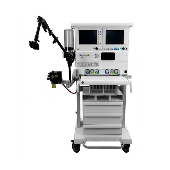
Page 24: Front View Of The Adu
Datex-Ohmeda ADU Front view of the ADU Figure 1 Front view of the ADU flush control (13) Anesthesia Monitor 10” LCD color display (2) Pipline gas inlets’ pressure gauges (14) ComWheel Fresh gas outlet (15) Aladin, vaporizer cassette Compact patient circuit... -
Page 25: Rear View Of The Adu
System description Rear view of the ADU Figure 2 Rear view of the ADU Auxiliary Air/O /vacuumoutlets (optional) Cylinder yokes (optional) Auxiliary mains supply outlets (optional) Gas supply and scavenging connectors Scavenging ejector with flow indicator or scavenging flow indicator (optional) Rear panel functions Mains outlet for Anesthesia Monitor ADU mains power cord... -
Page 26: Auxiliary Mains Outlets And Gas Supply Inlets
Datex-Ohmeda ADU Auxiliary mains outlets and gas supply inlets The three auxiliary mains outlets are reserved for monitors and other electrical devices mounted on the ADU. Figure 3 Auxiliary mains outlets (1) Figure 4 Gas supply inlets (to the left) and scavenging ejector (to the right) -
Page 27: Functional Units
System description Functional units Figure 5 Functional units Wall Gas Unit, A-WGU Fresh Gas Control Unit, A-FGC1 Central Electronics, A-ELEC Electronic Ventilator, A-EV1 Bellows Block, A-BB Document No. 8502852... -
Page 28: Ventilator With Compact Patient Circuit
Datex-Ohmeda ADU Ventilator with compact patient circuit Figure 6 Compact patient circuit Fresh gas supply connection (Common gas outlet) Circuit boom Compact block Valves for inspiration and expiration Locking/releasing ledge for absorber canister Absorber canister Inspiration and expiration hoses with Y-piece... -
Page 29: Compact Block
System description Compact Block Gas flow within the Compact Block and the single use absorber. Pictures below shows the principles of the gas flow through compact block. There are two models of compact blocks and the pictures below illustrate a compact block ACC1. Insp Insp Figure 9... -
Page 30: Frame Pneumatics (A-Auf)
Datex-Ohmeda ADU Frame Pneumatics (A-AUF) Functional description The wall gas unit is in the Frame, and offers all customer specific pneumatic connections: gas inlets for O , Air and N O / connections for extra gas bottles / vacuum (VAC) / evacuation (EVAC) / pressure gauges for central and bottle supply pressures. -
Page 31: Fresh Gas Control Unit (A-Fgc1)
System description Fresh Gas Control Unit (A-FGC1) The wall gas unit is connected to the gas inlets of the fresh gas control unit inside the gas distribution block. The fresh gas control unit includes the flow controls and the vaporizer gas flow circuit. Flow controls The O O and Air flows are adjusted by means of mechanical needle valves. -
Page 32: Manual Mode
The disposable CO absorber may be changed during Auto ventilation without causing a circuit leak. The Datex-Ohmeda Standard Patient Circuit has a large absorber which contains 900 g soda lime. The CO absorbent may be changed during Auto ventilation without causing a leak. -
Page 33: Symbols
System description Symbols Symbols and text on transport packages The contents of the package are fragile and must be handled with care. Indicates the correct upright position of the transport package. The transport package must be kept in a dry environment. Indicates the temperature limitations within which the transport package should be kept and handled. - Page 34 Datex-Ohmeda ADU Silence alarm indicator Power on Stand by Variability Rotation in two directions flush Flow directions • Silence alarm • Alarm silenced for a given time • All alarm silenced Remaining battery capacity Battery empty Empty Battery charging Charge...
- Page 35 System description Fresh gas flow inlet Bellows connection Do not expose the bellows chamber to side force. Keep free from gas cylinders, cables etc. Side force or impact on the chamber may create a leak in the ventilator bellows drive circuit. Gas flow direction Single use Expiration connector...
- Page 36 Datex-Ohmeda ADU This page is intentionally left blank. 3-14 Document No. 8502852...
-
Page 37: Installation Instructions
Installation instructions 4 INSTALLATION INSTRUCTIONS WARNING The installation of the ADU must be done by properly trained and authorized technical personnel. Introduction and requirements The ADU is manufactured according to your order. The ADU must be connected to mains electrical power and gas supplies as specified in the ”Technical Specifications”... -
Page 38: Connections Of The Anesthesia Delivery Unit
Datex-Ohmeda ADU Connections of the anesthesia delivery unit. Figure 1 Rear connection panel Mains connector for Anesthesia Monitor or Capnomac Ultima. ADU mains power cord (or connection cord for Auxiliary Electrical Outlets). Product ID labels. Contains information on type of device, identification number, year of manufacture and electrical requirements. - Page 39 Installation instructions Figure 3 Gas supply inlets Nitrous oxide inlet Air inlet Oxygen inlet Gas scavenging outlet (EVAC) Vacuum inlet (optional) Each connector is designed to be coupled with its corresponding hose. The connectors and hoses are color coded. Power cord •...
- Page 40 Datex-Ohmeda ADU Batteries CAUTION If the batteries become discharged they will be damaged. Even if the ADU not is being used the batteries will slowly be discharged. NOTE: If the ADU is stored more than two months it is recommended to connect the ADU to mains and let the batteries be fully charged.
- Page 41 Installation instructions Figure 5 A-SEJ2 With flow indicator Adjust the scavenging flow with its control. Check that the waste gas flows through the EVAC outlet. Connect the scavenging hose from the EVAC outlet to the central scavenging system of the hospital.
-
Page 42: Installation Of Monitors
Suitable software versions are stated in the “Transference of Parameters” paragraph. Prerequisites Serial interface connector Use only official Datex-Ohmeda monitor cables for the Anesthesia Monitor and Capnomac Ultima. Serial connector (X1) configuration The connector is located on the Digipower board of the Central Electronics unit. -
Page 43: The Anesthesia Monitor Central Unit
Installation instructions The following Interfacing setting defaults may be configured on the Install menu: • • Multi • None / PC Figure 7 Text displayed in ThermoScroll menu: Gas, Multi and None. When Multi is selected the Prompt text will be: ‘Gas and spiro digits and CO waveform from D-O S/5 or AS/3 multi... -
Page 44: Anesthesia Monitor Video Display 14'' (D-Vhc14)
Datex-Ohmeda ADU Install the Central Unit of the monitor into the monitor frame rack. Fasten the two screws holding the central unit and monitor frame rack together. Connect the Serial Connector of the ADU to the Serial Interface connector of the UPI board in the monitor with the ADU Monitor Cable. -
Page 45: Capnomac Ultima
Installation instructions Draw the display cable through the ADU and connect it to the monitor. Connect the cable from the back of the monitor LCD display with two screws to the frame of the ADU. Reinstall the top shelf and back panels. Capnomac Ultima Turn off the ADU and the monitor. -
Page 46: Configuring The Software
The unit may be operated without changing these screen default settings. Datex-Ohmeda has designed the ADU so that the default settings may be changed to meet hospital standards. Once changed and saved, the defaults will become active whenever the unit is turned on. -
Page 47: Country Specific Requirements
Installation instructions Country specific requirements In some countries law requires the following software configuration alternatives. They are however available to all users. ”French and U.S. version” (Compulsory in France and the U.S.) User alarm ‘Volume monitor removed’ is displayed if no volume monitor is connected or it is switched off. -
Page 48: User Defaults Configuration
Datex-Ohmeda ADU User defaults configuration WARNING A reconfiguration of the user defaults must be done by a trained physician or by trained personnel on order of a physician. The following Screen Layout defaults may be configured: • Waveform fields • Fresh gas field •... - Page 49 Installation instructions The following Alarm setting defaults may be configured: • High and low alarms limits for any parameter • Alarm volume • Reminder volume If the factory default settings for High and low alarm limits are changed, they cannot be reset by the factory defaults function.
- Page 50 Datex-Ohmeda ADU The following User Configuration setting defaults may be configured in Install menu: • Language • Volume • Mode • Ambient pressure • French and US version • Japanese If the factory default settings are changed for these functions, they cannot be reset by the factory defaults function.
-
Page 51: Saving The Configuration
Restart the ADU and check that the configuration corresponds to the values in the default configuration worksheet. Default configuration worksheet For the user configuration of the Datex-Ohmeda Anesthesia Delivery Unit. Instructions Use this form to select the function and parameter defaults to be changed and saved as a new default configuration. -
Page 52: Identification Of The Configuration
Datex-Ohmeda ADU Go to SETUP/INSTALL to save the changes. After configuration, save this identification page and other worksheet pages for future reference. Identification of the configuration Identification number for ADU frame, A-AUF, is located on back of the unit. Fill in the customer or the hospital name, date of installation and signature of the person who performed the installation. -
Page 53: Default Configuration Worksheet For The Adu (No. 1 Of 4)
Installation instructions Default configuration worksheet for the ADU (No. 1 of 4) NOTE: Parameters with the prefix * can not be reset by the factory defaults function. Resetting must be done manually. Setup - Screen layout Parameter Default select. alternatives User default ( ) = factory set Write down new... - Page 54 Datex-Ohmeda ADU *Ambient pressure Sea level; 1013 mbar *French option (No) /Yes * Japanese version (No) /Yes 4-18 Document No. 8502852...
-
Page 55: Default Configuration Worksheet For The Adu (No. 2 Of 4)
Installation instructions Default configuration worksheet for the ADU (No. 2 of 4) Install - Interfacing *Interfacing GAS (Multi) None/ PC Install - Trend setup Select Page (Page 1) Page 2 Page 3 (Page 4) (Page 5) (Page 6) Page 1 Select Graph (Ppeak) Pplat Peep Pmin MV I:E Pause Vent. - Page 56 Datex-Ohmeda ADU Mix Color Graph Scale Graph Height Cursor on/off (ON)OFF Page 5 Select Graph Graph Type Graph Color Mix Color Graph Scale Graph Height Cursor on/off (ON) OFF Page 6 Select Graph Graph Type Graph Color Mix Color Graph Scale...
-
Page 57: Default Configuration Worksheet For The Adu (No. 3 Of 4)
Installation instructions Default configuration worksheet for the ADU (No. 3 of 4) Install - Trend setup - Change field Field 1 OFF; (Ppeak,.); Vent ; TV; RR; MV; O O, Air; AA; I:E; Pause; I:E, Pause; Total; O %; CO , He;... -
Page 58: Default Configuration Worksheet For The Adu (No. 4 Of 4)
Datex-Ohmeda ADU Default configuration worksheet for the ADU (No. 4 of 4) Ventilator - Options Trigger Window 5 - 95 % (50 %) Inspiratory Pause OFF 5 10 15 20 (25) 30 35 40 45 50 55 60 Inspiratory Rise... -
Page 59: Maintenance
Maintenance 5 MAINTENANCE Schedule and maintenance kits For safe, reliable function and operation of the ADU, regular maintenance must be carried out as described in the “User’s Reference Manual” supplemented by the maintenance procedures in this section. There are four different check and maintenance procedures for the ADU, which should be carried out according to the schedule below. -
Page 60: Tools
• Electrical safety tester • Test lung (2 litter manual bag) • High pressure tester or Datex-Ohmeda high pressure test adapter (P/N 8500002) • Cassette pressure adapter (P/N 8500006). Note that this tool is only necessary during calibration. • Pilot pressure connector for (P/N 735096). Note that this tool is only necessary during calibration and check of the inlet pressure regulator. -
Page 61: Passwords
Maintenance Passwords ‘Diagnostics Password’ gives access to all Service Menu pages but not to the Calibration Menu pages. ‘Calibrations Password’ gives access to all Service Menu pages. It is also possible to alter calibration values and to reset Error History. Layout of service/diagnostics and calibrations pages Each page contains a list of items and a blue message field. - Page 62 Maintenance Figure 1 Service menu overview Document No. 8502852...
-
Page 63: Maintenance Procedures
Maintenance Maintenance procedures Step 0: Preparations before installation of maintenance kits Disassembly and reassembly of covers Tools: Allen wrench 4 mm Remove the pipeline gas supplies and disconnect the mains. Remove the 8 Allen screws securing the rear plastic cover. To remove the side panels (2, 3 and 4) remove the Allen screw with toothed washer. -
Page 64: One Year Maintenance
Datex-Ohmeda ADU One year maintenance Step 1: Replacing the gas inlet o-rings Spare parts: Gas inlet O-rings (3 pcs) 65399 for NIST connectors Tools: Wrench Remove the gas supply hoses from the A-WGU gas inlet connectors and replace the O-rings supplied in the one year kit. - Page 65 Maintenance Step 3: Replacing the dust filter Spare parts: Dust filter 871558 Replace the dust filter at the back of the Central Electronics unit. Figure 5 The dust filter Document No. 8502852...
- Page 66 Datex-Ohmeda ADU Step 4: Replacing the gasket between the Bellows Block and the Bottom Plate Spare parts: Gasket 886394 Replace bottom plate gasket underneath the bellows block with the new one from the kit. Figure 6 Bottom plate with gasket...
- Page 67 Maintenance Step 6: Replacing the o-rings on the Bellows Block connectors Spare parts: O-ring for Patient Circuit connector, 65374 (1) O-ring for Manual Bag connector, 656507 (2) located inside the connector Replace both O-rings with new ones supplied in the kit. Coat the new O-rings with a thin layer of PTFE based lubricant.
- Page 68 Datex-Ohmeda ADU Step 8: Replacing the O-ring on the Fresh Gas Outlet Spare parts: O-ring for Fresh Gas Outlet 65374 Replace the O-ring on the Fresh Gas Outlet with the new O-ring supplied in the kit. Step 9: Replacing the O-rings in cassette housing Spare parts: O-rings (2 pcs) 65371 Pull out the Aladin cassette and remove the O-rings in the bottom of the cassette slot.
- Page 69 Maintenance Step 10: Replacing the reservoir tube Spare parts: Reservoir tube 8500074 Straps 00036008 Tools needed: Allen wrench, 4 mm The reservoir tube is located in a ”tray” which is accessible behind the side panels of the unit. Disconnect the end of the tube (1) from its connector on the left side of the unit. Remove the 2 screws holding the tray in place (2) on right side of the unit and carefully pull out the tray.
-
Page 70: Three Year Maintenance
Datex-Ohmeda ADU Three year maintenance Step 11: replacing the expiration and PEEP valve membranes and O-rings Spare parts: Expiration valve membranes (2 pcs) 886432 O-rings (3pcs) 65363 O-ring (1pcs) 050083349 Tools: Crosshead Pozidriv screwdriver Allen wrench 2, 5 and 3 mm NOTE: Do not use membranes older than three years! Take out the EXP. - Page 71 Maintenance Replace the valve membranes (item 1 in picture below). NOTE: Be sure that new membranes are well seated around the steel plates before reinstalling the valves in the housing. NOTE: Do not apply any kind of lubricant to the membranes Refit the lid and tighten the six Allen screws.
- Page 72 Datex-Ohmeda ADU Step 12: Replacing the batteries in the Central Electronics (Three years) Spare parts: Batteries (4 pcs) 891389 Tools: Allen wrench 4mm Cross-head Pozidriv screwdriver NOTE: All batteries must be replaced at the same time. NOTE: Screws 63611 and 61721 are used to fasten top and side covers. Replace worn screws.
- Page 73 Maintenance Remove both side covers, by unlocking the screws on each side, see figure below. Figure 17 Removing the A-ELEC side cover by unlocking screws Unfasten the 4 screws (see figure below) securing the Mains board to the A-ELEC and carefully fold it down .
- Page 74 Datex-Ohmeda ADU Disconnect the cables Yellow (X2) and Black (X3) from the rectifier board. Figure 20 Rectifier board socket connections Remove the 4 screws (2 at each side of the A-ELEC module) that hold the battery and transformer tray as figure below.
- Page 75 Maintenance 11. Disconnect the following wires connected to the Battery charger board connections X2, X3, X4 and X5 as figure below. Connections chager board BAT A BAT B TEMP A TEMP B Figure 23 Battery charger board 12. Push out the battery transformer assembly tray from the A-ELEC, push from the the transformer side.
- Page 76 Datex-Ohmeda ADU Figure 24 Transformer unit Figure 25 Transformer unit 5-18 Document No. 8502852...
- Page 77 Maintenance Figure 26 Transformer unit Figure 27 Battery cable connectors NOTE: Battery cover is also labeled 15. Reassemble all parts and covers in reversed order. 5-19 Document No. 8502852...
- Page 78 Datex-Ohmeda ADU Step 13: Checking the error detection function of the vaporizer heating resistor Tools: Allen wrench 4 mm Cross-head Pozidriv screwdriver Open the cover of the fresh gas unit by removing its retaining screws (9 Pozidriv and 4 Allen screws).
-
Page 79: Other Maintenance
Maintenance Step 14: Changing the chamber seal and o-rings of the Bellows Block Tools: Crosshead Pozidriv screwdriver (PDZ1) Spare parts: Chamber seal 886412 O-rings 65394 (3 pcs) 656499 (2 pcs) 65389 (1 pcs) Remove the three retaining screws and bellows collar (1). Remove the bellows chamber seal (2). - Page 80 Datex-Ohmeda ADU Figure 30 Compact Circuit A-CC1, exploded view 5-22 Document No. 8502852...
- Page 81 Maintenance Step 16: Compact Circuit Block, A-CC2 (One year maintenance) Spare parts: 8570071, 8570069 Tools: Included in kit. Exchange the old parts (1 to 9) for the new parts in the kit 8570071 as shown below. Exchange the valve covers (10) with new ones from kit 8570069 as shown below. Note that the valve cover kit 8570069 is not part of the regular A-CC1 one year maintenance kit, but it is recommended to be replaced once a year as a preventive action.
- Page 82 Datex-Ohmeda ADU Step 17: O flush (Every 6th year, applies to units with A-WGU-00) Spare parts: 90700 Tools: Allen wrench 4mm Cross-head Pozidriv screwdriver Disconnect the gas supply tubing from the wall connectors. Remove the gas bottles from the yokes.
- Page 83 Maintenance Step 18: O flush kit (Every 6th year. Applies to units with A-WGU-01-02-03 and table mounted O flush) Maintenance kit: 8500993 including O-ring 3.1x1.6 mm O-ring 9.1x1.6 O-ring 12.1x1.6 mm O-ring 3.3x2.4 mm Specific tools: 16 mm wrench PTFE based lubricant The oxygen flush can be mounted in two different places depending on ADU type: Frame panel mounted.
- Page 84 Datex-Ohmeda ADU Remove the left side panel and disconnect the A-WGU/A-FGC1 and A-WGU/A-EV1 multi connectors (including seals) secured by Allen screws (2 each). Carefully remove the A-WGU from the frame. Unscrew the O flush assembly from its manifold by using the 16 mm wrench.
-
Page 85: Post-Maintenance Procedure
Maintenance Step 19: Replacing the Static RAM IC on processor board B-CPU2..01 or B- CPU4..01 Board (every 8th year) Spare parts: Static SRAM M48T18 No. 197230 Disconnect the mains power. Remove the CPU board from the Central Electronics module. Replace the Static RAM as in figure below. Reinstall the CPU board and perform a Functional check. -
Page 86: Kits For Maintenance
The numbers in brackets is the quantity of this part in the kit, the order number relates to the individual parts. NOTE: Parts for maintenance of patient circuits are listed in Datex-Ohmeda Accessories guide. Contents of One year maintenance kit Item description Order No. - Page 87 Maintenance Other maintenance parts Item description Order No. One year A-CC1 maintenance kit 42-70015-00 One year A-CC2 maintenance kit 8570071 Valve covers kit A-CC1 and A-CC2 recommends 8570069 to be replaced once a year flush assembly (every 6th year). For A-WGU- 90700 flush maintenance kit (every 6 th year).
- Page 88 Maintenance Figure 38 Maintenance parts 5-30 Document No. 8502852...
-
Page 89: Functional Check
The flow and pressure test devices should have an accuracy of +/-2.5% or better. Datex-Ohmeda assumes that technical and biomedical professionals know how to use the device available at his/her institution. Therefore, test device instructions are not included in this manual. -
Page 90: Frame
Datex-Ohmeda ADU Setup Turn on the ADU and push the key. Select Install and enter the distributor password. Select Install - User Config - Ambient pressure. Select and enter the external air pressure (see the chart below). The first row shows the height above sea level (meters) and the second row... -
Page 91: Wall Gas Unit
Maintenance Wall Gas Unit Step 2: Central inlets Settings: Pipeline supplies connected Flow closed ADU off Check that the pressure gauges in the gas supply inlets show 2.7 - 8 × 100 kPa (39.6 - 118 psi) each. Step 3: High pressure leakage and non-return valves Equipment needed: Calibrated test device High pressure test adapter Wrench... - Page 92 Datex-Ohmeda ADU Select Previous menu - Fresh gas control and perform step 7 and 8 but for N NOTE: If any of the pressure sensors are out of tolerance, they need to be recalibrated. For O and air pressure sensors, please refer to “Part II” section “Electronic Ventilator - Calibration” in this manual.
- Page 93 Maintenance Step 4: Cylinder pressure and yoke pressure regulators This check is only intended for ADU with Yokes installed. Settings: ADU on Pipeline supplies gases disconnected Flows closed Gas cylinders disconnected Manual mode Air/N O switch in N O position To check cylinder pressure, cross connection and tightness: Relieve the system from gas pressure by opening the N O flow needle valve fully, the O...
- Page 94 Datex-Ohmeda ADU Cylinder pressure Adjust 0 /Air reg. Adjust N O reg. x 100 kPa x 100 kPa x 100 kPa 20-60 290-870 4-3.8 58-55 3.7-3.5 54-51 60-100 870-1450 3.8-3.5 55-51 3.5-3.2 51-46 100-140 1450-2030 3.5-3.2 51-46 140-200 2030-2900 3.2-3.0...
- Page 95 Maintenance Open the air flow to approx. 2 l/min. Check that the monitor shows 21 ± 3% O concentration. Close the air flow and open the O flow to approx. 2 l/min. Check that the monitor shows 100 ± 3% O concentration.
- Page 96 Datex-Ohmeda ADU Check that the test device does not indicate any flow when the ”O flush” control is released. Disconnect the test device and reconnect the fresh gas hose to the fresh gas outlet. Step 7: Evacuation outlet Settings: Pipeline supplies gases connected...
-
Page 97: Central Electronics
Maintenance Central Electronics Step 8: Auxiliary mains socket outlets Equipment needed: Voltmeter Check all auxiliary outlets for correct voltage. Step 9: Batteries Unplug the power cord from the power supply outlet. Check that the message ‘Mains power lost’ is displayed and that the ADU works on battery power for 15 minutes. Meanwhile, continue the Functional Check. - Page 98 Datex-Ohmeda ADU Step 11: Keyboard Select Keyboard and push each softkey on the keyboard. Check, when pushing a key, that the corresponding text on the display changes from yellow to red and that there is a beep sound. ComWheel Select Upper LED with the .
-
Page 99: Fresh Gas Control Unit
Maintenance Fresh Gas Control Unit Step 14: Fresh Gas Leakage Equipment: Calibration test device and fittings Settings: The N O/Air switch in N O position Pipeline supplies gases connected No Aladin cassette connected Test range: 35-60 cm H Figure 46 Fresh Gas Leakage test setup Select low pressure range on test device. - Page 100 Datex-Ohmeda ADU Step 15: Gas flow controls Equipment needed: Calibrated test device Settings: Pipeline supplies gases connected Test range: 0-15 l/min. (for flows less than 5 l/min. the tester should be setup to read hundreths (Two digits to the right of the decimal).
- Page 101 Maintenance Check that the fan works by cautiously inserting one hand into the cassette housing to feel the airflow. On/Standby Turn the switch to Standby position to leave the Service Menu and turn it on again. Select Bypass Check- Normal screen and Confirm. Step 17: Fresh gas outlet safety valve Equipment needed: Calibrated test device...
- Page 102 Datex-Ohmeda ADU Step 18: N O / O ratio control The N ratio control limits the N O flow to a maximum of 75% of the total flow. This assures a minimum O concentration of 25%. Equipment needed: Calibrated gas monitor Settings: Pipeline supplies gases connected.
- Page 103 Maintenance Step 19: Agent control check Equipment needed: Calibrated Gas monitor. (Use QUICK CAL™ Calibration Gas, 755582 for the Capnomac Ultima or the Filled Enflurane or Sevoflurane Aladin cassette Settings: Test lung connected Pipeline supplies gases connected Scavenging system connected Monitor sampling line connected between fresh gas outlet and fresh gas hose Manual mode and APL valve set to open position Test range:...
- Page 104 Datex-Ohmeda ADU Following the chart below, set O to 1 l/min. and 8 l/min. respectively and select 0.5%, 3.0% Agent wheel and 5.0% agent by turning the . Close all other flows. Verify the AA% for each setting and observe the checks later in this section. Let the system stabilize for 1 minute after each agent selection.
- Page 105 Maintenance ambient pressure. Therefore the values in the table “AA% at sea level ambient pressure” above are only valid at sea level ambient pressure. In a different situation, e.g. if the external air pressure is not 1013 mbar (760 mmHg), the solution is to calculate an AA% factor.
-
Page 106: Electronic Ventilator
Datex-Ohmeda ADU Step 20: Aladin Cassettes Settings: ADU on Pipeline supplies gases connected For units equipped with an Aladin cassette for Desflurane: With the cassette inserted and locked in its proper position, check that the liquid level indicator on the display works. - Page 107 Maintenance Step 22: Circuit pressure measurement Equipment needed: Calibrated test device Settings: ADU on Manual mode Y-piece connected to ADU occluder cone on bellows block Pipeline supplies gases connected Test range: 0-50 cmH Figure 53 Circuit pressure measurement test setup Enter the relevant range on the test device.
- Page 108 Datex-Ohmeda ADU Step 23: Pilot valve pressure Equipment needed: None Settings: ADU on Pipeline supplies gases connected Setup Push the key. Select Service menu and enter the Diagnostics or Calibration Password. Select Diagnostics - Ventilator Figure 54 Diagnostic page A-EV1 Check if the ‘Pilot press err’...
- Page 109 Maintenance Step 24: Delivered tidal volume Equipment needed: Calibrated test device Test resistance, 535335100 Settings: Manual mode Pipeline supplies gases connected Test range: 0-1500 ml Figure 55 Delivered tidal volume test setup Figure 56 Test resistence Test device This test procedure is written for a flow-based test device, meaning that the inspiration flow from the ventilator is leaving the test device on its outlet port to the atmosphere.
- Page 110 Datex-Ohmeda ADU Connect a leak free hose between the bellows block circuit connection and the resistance attached to the test device. Select the following parameter values for the Ventilator: Volume 1000 Rate 1:2.0 Insp.Pause Turn the Auto/Man. switch to Auto mode. Let the ventilator operate for one minute.
- Page 111 Maintenance Step 26: PEEP function test Equipment needed: Test lungs Settings: ADU on Pipeline supplies gases connected Manual mode Patient circuit and a 2 L test lung connected to the Y-piece Connect a 2 l test lung to the Y-piece. Set the fresh gas air flow to 1 l/min.
-
Page 112: Electrical Safety
Datex-Ohmeda ADU Electrical safety Step 28: Electrical safety test Equipment needed: Electrical safety tester The ADU is classified as Class I, Type B according to IEC 60601-1. Tests recommended to perform once a year are: • Protective earth resistance (see measuring points below) •... -
Page 113: System Check
Maintenance System check Step 29: System check System check Push the button and carry out the Full check as described in the “User’s Reference Manual”. 5-55 Document No. 8502852... - Page 114 Datex-Ohmeda ADU This page is intentionally left blank. 5-56 Document No. 8502852...
-
Page 115: Technical Specifications
Technical specifications 6 TECHNICAL SPECIFICATIONS General Specifications valid for ADU ID: 40 000 000 and greater Dimensions Basic unit with cart Height Two optional heights: 1410 / 1540 mm Display viewing level 1242 / 1372 mm Depth 780 mm Width 840 mm Floor space 705 mm x 726 mm... -
Page 116: Electrical Requirements
Datex-Ohmeda ADU Electrical requirements The unit is designed to be powered from the mains power supply. A back-up battery function is provided. Power supply 220 - 240 VAC (±10%), 50/60 Hz or 100 - 120 VAC (±10%), 50/60 Hz Maximum power consumption... -
Page 117: Trends
Technical specifications Trends Trend resolution Resolutions for continuous data: up to 20 min. 10 sec. up to 2 hours 1 min. up to 4 hours 2 min. up to 12 hours 6 min. up to 24 hours 12 min. Continuous trend information together with time discrete events are stored for the latest 24 hours with one-minute resolution for all ADU parameters. -
Page 118: Gas Delivery
Datex-Ohmeda ADU Gas Delivery Gas supply Wall supply Gas connectors - AIR - N O - VAC (optional) - EVAC Inlet pressure 270 - 800 kPa (2.7 - 8 bar) Gauges , Air, N O: 0 - 1000 kPa (0 - 10 bar) Accuracy of gauges ±... -
Page 119: Electronically Controlled Vaporizer And Aladin Cassette
Technical specifications Accuracy specifications applied to above mentioned nominal adjustment ranges. Available maximum flows may exceed the above mentioned values. Electronic flow measurement Accuracy * ± 10 % or ±20 ml/min, whichever greatest ± 10 % or ±20 ml/min, whichever greatest ±... - Page 120 Datex-Ohmeda ADU Liquid capacity Maximum 250 ml Normally possible to fill up when cassette 150 ml indicator shows empty (residual volume 100 ml) Cassette Empty weight Enflurane, Isoflurane , Sevoflurane with key filler: 2.0 kg Halothane with keyed filler, Sevoflurane Quik Fil: 2.5 kg...
-
Page 121: Ventilation
Technical specifications Ventilation Electronic Ventilator including Bellows Block Description The ventilator is an electronically controlled, time cycled flow generator delivering tidal volumes compensated for the actual inspiratory fresh gas flow and measured breathing circuit compliance. The ventilator includes a maintenance free internally integrated PEEP proportional valve. The ventilator incorporates a switch operation from manual or spontaneous ventilation (Man/Spont) to controlled mechanical ventilation (AUTO). - Page 122 Datex-Ohmeda ADU Controls Respiration rate 2 – 60 breaths/minute (factory default, 10) Resolution 1 breath/minute Patient weight (kilos) 3 - 100 kg Resolution 0.5 kg within 3-10 kg range 1 kg within 10-30 kg range 5 kg within 30-100 kg range Inspiration/expiration ratios 1:4.5, 1:3, 1:2.5, 1:2, 1:1.5, 1:1, 2:1, (factory...
- Page 123 Technical specifications Accuracy Tidal volume accuracy 20 - 50 ml: ±20 % of set value or 5 ml, whichever is the greater. ≥50 ml: typically ±5 % of set value or 10 ml, whichever is the greater. In extreme cases not more than ±10 %.
-
Page 124: Patient Breathing Systems
Datex-Ohmeda ADU Patient Breathing Systems Refer to the technical information tables for the Compact Block patient circuit and the standard patient circuit with absorber. Any breathing circuit compatible with a 22/15 mm coaxial fresh gas outlet may be used. A patient circuit used together with tubing and Bellow block must comply with the prEN740 accepted resistance stipulation. -
Page 125: Forms And Charts
Forms and charts 7 FORMS AND CHARTS The following documents may come in very handy to keep a check on what to do and what has been done during long and complicated checking and maintenance procedures. Also included are a number of useful diagrams and tables. -
Page 126: Installation Check List, Adu Id: 40 000 000 And Greater
Datex-Ohmeda ADU Installation check list, ADU ID: 40 000 000 and greater Serial number: Date: (YY/MM/DD) Hospital: Performed by: Setting up the anesthesia delivery unit Unpack the unit according to the “Open Me First” instructions Add pipeline inlet connectors to gas hoses... -
Page 127: Functional Check Procedure, Adu Id: 40 000 000 And Greater
Forms and charts Functional check procedure, ADU ID: 40 000 000 and greater A-AUF ID: Date: (YY/MM/DD) Hospital Performed by: OK Failed OK Failed Leak tests 5. Cross-connections 21± 3% O AUTO mode ml/min 100 ± 3% O MAN mode ml/min 0: 50 ±... -
Page 128: Ventilator
Datex-Ohmeda ADU OK Failed OK Failed 16. Fan cassette housing 24. Delivered tidal volume Set Tidal Rate Tolerance Tidal volume 17. Fresh gas outlet safety valve Volume ml / min ml / min Total Flow Limit Measured 1000 900-1100 10l/min... -
Page 129: Maintenance Schedule, Adu Id: 40 000 000 And Greater
Forms and charts Maintenance schedule, ADU ID: 40 000 000 and greater Serial number: Date: (YY/MM/DD) Hospital: Performed by: One year Three year Other One year maintenance ADU (Order No. 893641) Replace gas inlet connector O-rings (3) in A-WGU (3 pcs) Replace gas inlet filters and gaskets (3) in A-WGU (3 pcs) Replace dust filter in A-ELEC Replace gasket in A-BB... -
Page 130: Pressure Conversion Table
Datex-Ohmeda ADU Pressure conversion table cm H mm Hg 1 atm 1033 1.01 14.7 1 cm H 9.7 x 10 0.098 0.74 9.8 x 10 0.014 1 kPa 9.9 x 10 10.2 0.01 0.145 1 mm Hg 1.3 x 10 1.36... -
Page 131: Pneumatic Symbol Chart
Forms and charts Pneumatic symbol chart Guide to the symbols used in the pneumatic diagrams of this manual Document No. 8502852... -
Page 132: Pneumatic Chart Of The Electronic Ventilator A-Ev1
Forms and charts Pneumatic chart of the Electronic Ventilator A-EV1 Document No. 8502852... -
Page 133: Pneumatic Chart Of The Fresh Gas Control Unit A-Fgc1
Forms and charts Pneumatic chart of the Fresh Gas Control Unit A-FGC1 Document No. 8502852... -
Page 134: Health And Safety Declaration Form
Failure to complete the form or to comply with health and safety cleaning procedures, may endanger Datex-Ohmeda service personnel and may lead to delay in servicing the equipment. Equipment type/Product No: State if the equipment has been in contact... -
Page 135: Pneumatic Chart Of Table, Frame Without A-Fgfi
Forms and charts Pneumatic chart of Table, frame without A-FGFI 7-11 Document No. 8502852... - Page 136 Datex-Ohmeda ADU This page is intentionally left blank. 7-12 Document No. 8502852...
-
Page 137: Pneumatic Chart Of A-Wgu, Frame Without A-Fgfi
Pneumatic chart of A-WGU, frame without A-FGFI 7-13 Document No. 8502852... -
Page 138: Pneumatic Chart Of A-Wgu, Frame With A-Fgfi
Pneumatic chart of A-WGU, frame with A-FGFI 7-14 Document No. 8502852... -
Page 139: Pneumatic Chart Of Table, Frame Without A-Fgfi
Pneumatic chart of Table, frame without A-FGFI 7-15 Document No. 8502852... -
Page 140: Pneumatic Diagram Of Table, Frame With A-Fgfi
Pneumatic diagram of table, frame with A-FGFI 7-16 Document No. 8502852... -
Page 141: Revision History
Revision history 8 REVISION HISTORY This section contains a declaration of the revision status for: • The complete AS/3 and S/5 Anesthesia Delivery Unit • The software • The PC Boards NOTE: The reference numbers in the section may not be the same as the spare part order numbers, it is the number stamped on the board. - Page 142 Datex-Ohmeda ADU Software A-EV1 software A-FGC1 software Main software Initial release Ver. 7.2 Initial release Ver. 7.0 Initial release Ver. 5.1 (S- ADU97) March 1998. March 1998 March 1998 (S-ADU97) Ver. 7.3 Ref. Technical Bulletin Ver. 7.1 Ref Technical Bulletin Ver.
-
Page 143: Pc Boards
Revision history PC Boards ADU PC-Boards Release 1 Release 2 Release 3 Mains board. 893052 895052, March 1998 895378, April 1998 Change: One NTC resistor added to lower start- Change: Design changed. NTC resistor up current. mowed. Audio amplifier board. 881794 Battery charger board. - Page 144 Revision history ADU PC-Boards Release 1 Release 2 Release 3 A-AEV1 Flow sensor board. 884227 Only A-EV1 manufactured before September 1998. A-EV1 Flow sensor board 8500952 including zeroing valve. and AIR sensor board. 890413 898639, February 2001 (change due to discontinuation of 890413. Ref.
- Page 145 Revision history ADU PC-Boards Release 1 Release 2 Release 3 O pressure sensor board. 890413 898639, February 2001. (change due to discontinuation of 890413. Ref. Technical bulletin ADV STO 01 003. Cassette Identification board. 884118 8504118, September 2001 Number on board changed. No functional changes.
- Page 146 Datex-Ohmeda ADU This page is intentionally left blank. Document No. 8502852...
-
Page 147: Technical Bulletins
Technical bulletins 9 TECHNICAL BULLETINS Document No. 8502852... -
Page 149: 10 Glossary
Glossary 10 GLOSSARY Abbreviations For an anesthesiologic vocabulary please see the “User´s Reference Manual”. A-VHAL Aladin cassette Halothane (Key filler) Anesthetic Agent A-VISO Aladin cassette Isoflurane A-AS1 Aladinslot (Key filler) A-AUF Frame Pneumatics A-VENF Aladin cassette Enflurane (Key filler) A-AXA1 Extra air outlet A-VSEV Aladin cassette Sevoflurane... - Page 150 Datex-Ohmeda ADU DISS Diameter-Index Safety International Organisation System for Standardization alt. Deutscher Kalibrierdienst Isoflurane D-LCCADU ADU Display Monitor Display (integrated) Kilo Pascal (unit of LCC10W pressure) Datex-Ohmeda D-VHC14 Monitor display 14” Liter D-VNC15 Monitor display 15” Liquid Crystal Diplay See also D-LCCADU Europäische Norm...
- Page 151 Glossary Airway Pressure User´s Reference Manual Computer United States Printed Circuit Board PCMCIA Software Card Vacuum alt. Pressure Controlled Voltage Alternating Current Ventilation VBUS Voltage Bus PEEP Positive End Expiratory Pressure Volume Controlled Ventilation Part Number Voltage Dependent Resistor Pcirc Circuit Pressure Vol.
- Page 152 Datex-Ohmeda ADU This page is intentionally left blank. 10-4 Document No. 8502852...
-
Page 153: Technical Description A-Auf
Technical description A-AUF TECHNICAL DESCRIPTION A-AUF General The main part of the Frame pneumatics is built into the wall gas unit (A-WGU) and comprises: • Pipeline gas inlets connections • Yokes for gas cylinders (option) • High pressure gauges for pipeline and cylinder pressure •... - Page 154 Datex-Ohmeda ADU • Table mounted Oxygen flush without Fresh Gas Flow Indicator • Table mounted Oxygen flush with Fresh Gas Flow Indicator The A-WGU pneumatic drawings are divided into the following sections: Section A -Central inlets Section B - Reserve gas inlets...
- Page 155 Technical description A-AUF A-WGU mounted oxygen flush without fresh gas flow indicator Figure 1 A-WGU mounted oxygen flush without fresh gas flow indicator Document No. 8502853...
- Page 156 Technical description A-AUF A-WGU mounted oxygen flush with fresh gas flow indicator Figure 2 A-WGU mounted oxygen flush with fresh gas flow indicator Document No. 8502853...
- Page 157 Technical description A-AUF Table mounted oxygen flush without fresh gas flow indicator Figure 3 Table mounted oxygen flush without fresh gas flow indicator Document No. 8502853...
- Page 158 Technical description A-AUF Table mounted oxygen flush with fresh gas flow indicator Figure 4 Table mounted oxygen flush with fresh gas flow indicator Document No. 8502853...
-
Page 159: Technical Description Of The Wall Gas Unit
Technical description A-AUF Technical description of the Wall Gas Unit Pipeline inlets See Section A in pneumatic drawings. There are pipeline gas inlets for O (1), Air (2) and N O (3). Each inlet consists of: • Connector (inlet) • Hose nipple connector (outlet) •... -
Page 160: Gas Distribution
Datex-Ohmeda ADU Gas distribution See Section C in pneumatic drawings. This section distributes input gas from pipeline inlets and reserve gas cylinders to the A-WGU. There are non-return valve (11) to prevent back filling of the cylinders. Safety valves (12) for input gas is mounted on the gas connection block in the WGU. -
Page 161: A-Wgu-00, Tubing And Component Location (Iso Version
Technical description A-AUF A-WGU-00, tubing and component location (ISO Version) Flush Figure 5 Wall Gas Unit A-WGU-00, tubing and component location (ISO Version) Document No. 8502853... -
Page 162: A-Wgu-00, Option (Iso Version
Datex-Ohmeda ADU A-WGU-00, option (ISO Version) A-AXO A-AXO A-AXA1 A-YO O A-YN A-YO A-AXVC1 A-AXAR A-SEJ1 Figure 6 Wall Gas Unit A-WGU-00, option (ISO Version) A-10 Document No. 8502853... -
Page 163: Tubing Connection Chart A-Wgu-0O (Iso Versions
Technical description A-AUF Tubing connection chart A-WGU-0O (ISO versions) Tube connected according to WGU tubing and component location (ISO version). Wall Gas Unit, without options (ISO) Tube/Pipe No. Tube type Length (mm) From 733472 -Flush Regulator 733472 -Flush Connection block -408 733472 Connection block-409 Regulator... -
Page 164: A-Wgu-00, Tubing And Component Location (Ansi Version
Datex-Ohmeda ADU A-WGU-00, tubing and component location (ANSI version) flush Figure 7 Wall Gas Unit A-WGU-00, tubing and component location (ANSI version) A-12 Document No. 8502853... -
Page 165: A-Wgu-00, Option (Ansi Version
Technical description A-AUF A-WGU-00, option (ANSI version) A-AXO A-AXA1 O A-YN A-YO A-YO A-AXVC1 A-AXAR A-SEJ1 flush Figure 8 Wall Gas Unit A-WGU-00, option (ANSI version) A-13 Document No. 8502853... -
Page 166: Tubing Connection Chart (A-Wgu-00 (Ansi Versions
Datex-Ohmeda ADU Tubing connection chart (A-WGU-00 (ANSI versions) Tubing connected according to wall gas unit tubing and component location. Wall Gas Unit, without options (ANSI) Tube/Pipe No. Tube type Length (mm) From 733472 -Flush Regulator 733472 -Flush Connection block -408... -
Page 167: A-Wgu-01, -02, -03 Without Options. Tubing And Component Location (Iso Version
Technical description A-AUF A-WGU-01, -02, -03 without options. Tubing and component Location (ISO version) Figure 9 Wall gas unit A-WGU-01, -02, -03 Without Options tubing and component location (ISO version) Tubing / Pipe data Type Length (mm) Routed from Routed to *407 733472 flush regulator... -
Page 168: A-Wgu-01, -02, -03 Without Options. Tubing And Component Location (Ansi Version
Datex-Ohmeda ADU A-WGU-01, -02, -03 without options. Tubing and component location (ANSI version) Figure 10 Wall gas unit A-WGU-01, -02, -03 Without options tubing and component location (ANSI version) Tubing /Pipe data Type Length (mm) Routed from Routed to *407 733472... -
Page 169: A-Wgu-01, -02, -03 Extra Gas Outlets Option
Technical description A-AUF A-WGU-01, -02, -03 extra gas outlets option Figure 11 Wall Gas Unit A-WGU-01, -02, -03 extra gas outlets option Tubing /Pipe data Type Length (mm) Routed from Routed to 733472 A-AXO21 Connection block 733472 A-AXA1 Connection block 733472 A-AXAR Connection block... -
Page 170: A-Wgu-01, -02, -03 Vacuum Vac2 Outlet Option
Datex-Ohmeda ADU A-WGU-01, -02, -03 vacuum Vac2 outlet option Figure 12 Wall Gas Unit AWGU-01, -02, -03 vacuum Vac2 outlet option Tubing /Pipe data Type Length (mm) Routed from Routed to 733479 Wall gas connection-VAC A-AXVCR A-18 Document No. 8502853... -
Page 171: A-Wgu-01,-02, -03 With Double Vac Outlets Option
Technical description A-AUF A-WGU-01,-02, -03 with double Vac outlets option Figure 13 Wall Gas Unit A-WGU-01,-02, -03 with double Vac outlets option Tubing /Pipe data Type Length (mm) Routed from Routed to 733479 T-connector Vac2 (A-AXVCR) 733479 T-connector Vac (A-AVC1) A-19 Document No. -
Page 172: A-Wgu-01,-02,-03 With Scavenging Flow Indicator Attached
Datex-Ohmeda ADU A-WGU-01,-02,-03 with scavenging flow indicator attached Figure 14 Wall Gas Unit A-WGU-01,-02,-03 with scavenging flow indicator attached Tubing /Pipe data Type Length (mm) Routed from Routed to 733479 Flow indicator Connection block 733479 Wall gas connection EVAC Flow indicator A-20 Document No. -
Page 173: A-Wgu-01, -02, -03 With Scavenging Ejector Attached
Technical description A-AUF A-WGU-01, -02, -03 with scavenging ejector attached Figure 15 Wall gas unit A-WGU-01, -02, -03 with scavenging ejector attached Tubing / Pipe data Type Length (mm) Routed from Routed to 733472 A-SEJ2 (incl. Flow indicator) Connection block 733479 A-SEJ2 (incl. -
Page 174: A-Wgu-01, -02, -03 Gas Cylinder Option O
Datex-Ohmeda ADU A-WGU-01, -02, -03 gas cylinder option O + Air (ISO version) Figure 16 A-WGU-01, -02, -03 gas cylinder option O + Air (ISO version) Tubing /Pipe data Type Length (mm) Routed from Routed to 72271 pipe -Yoke (1) -
Page 175: Air (Ansi Version
Technical description A-AUF A-WGU-01, -02, -03 gas cylinder option O + Air (ANSI version) Figure 17 A-WGU-01, -02, -03, gas cylinder option O + Air (ANSI version) Tubing /Pipe data Type Length (mm) Routed from Routed to 72271 pipe -Yoke (2) -Yoke pressure gauge 72271 pipe... -
Page 176: O (Iso Version
Datex-Ohmeda ADU A-WGU-01, -02, -03, gas cylinder option O O (ISO version) Figure 18 A-WGU-01, -02, -03, gas cylinder option O O (ISO version) Tubing /Pipe data Type Length (mm) Routed from Routed to 72271 pipe -Yoke (1) -Yoke pressure gauge... - Page 177 Technical description A-AUF A-WGU-01, -02, -03 gas cylinder option O O (ANSI version) Figure 19 A-WGU-01, -02, -03, gas cylinder option O O (ANSI version) Tubing /Pipe data Type Length (mm) Routed from Routed to 72271 pipe -Yoke (2) -Yoke pressure gauge 72271 pipe -Yoke (1)
-
Page 178: O (Ansi Version
Datex-Ohmeda ADU A-WGU-01, -02, -03 gas cylinder option O + Air + Air (ISO version) Figure 20 A-WGU-01, -02, -03, gas cylinder option O + Air + Air (ISO version) Tubing /Pipe data Type Length (mm) Routed from Routed to... -
Page 179: A-Wgu-01, -02, -03 Gas Cylinder Option O
Technical description A-AUF A-WGU-01, -02, -03 gas cylinder option O + Air + Air (ANSI version) Figure 21 A-WGU-01, -02, -03 gas cylinder option O + Air + Air (ANSI version) Tubing /Pipe data Type Length (mm) Routed from Routed to 72271 pipe Air-Yoke (2) -
Page 180: A-Wgu-01, -02, -03 Gas Cylinder Option O + Air + N O (Iso Version
Datex-Ohmeda ADU A-WGU-01, -02, -03 gas cylinder option O + Air + N O (ISO version) Figure 22 A-WGU-01, -02, -03 gas cylinder option O + Air + N O (ISO version) Tubing /Pipe data Type Length (mm) Routed from... - Page 181 Technical description A-AUF A-WGU-01, -02, -03 gas cylinder option O + Air + N O (ANSI version) Figure 23 A-WGU-01, -02, -03 gas cylinder option O + Air + N O (ANSI version) Tubing /Pipe data Type Length (mm) Routed from Routed to 72271 pipe...
-
Page 182: Frame Tubing Interfaces Between Modules. No A-Fgfi - Oxygen Flush Mounted To A-Wgu
Datex-Ohmeda ADU Frame tubing interfaces between modules. No A-FGFI - oxygen flush mounted to A-WGU Ventilator drive gas tube A-EV1 multi connector Bottle connector Circuit monitor connection SCAV connector A-FGC1 multi connector A-WGU/A-EV1 multi con- nector A-WGU/A-FGC1 multi connector Figure 24... - Page 183 Technical description A-AUF 733480 Monitor.P 360 A-EV1 connector A-BB Circuit Connection 733480 Circle P. A-EV1 connector A-BB Circuit Connection *) On A-WGU-00 is tube 518 (∅8mm) labeled 506 (∅6mm) and tube 515 (∅8mm) labeled 505 (∅6mm). A-31 Document No. 8502853...
-
Page 184: Frame Tubing Interfaces Between Modules. With A-Fgfi - Oxygen Flush Mounted To A-Wgu
Datex-Ohmeda ADU Frame tubing interfaces between modules. With A-FGFI - oxygen flush mounted to A-WGU. Ventilator drive gas tube A-EV1 multi connector Bottle connector Circuit monitor connection SCAV connector A-FGC1 multi connector A-WGU/A-EV1 multi con- nector A-WGU/A-FGC1 multi connector Figure 25 Frame tubing interfaces between modules with A-FGFI - oxygen flush mounted to A-WGU. -
Page 185: Frame Tubing Interfaces Between Modules. No A-Fgfi - Oxygen Flush Mounted To Table
Technical description A-AUF Frame tubing interfaces between modules. No A-FGFI - oxygen flush mounted to table Ventilator drive gas tube A-EV1 multi connector Bottle connector Circuit monitor connection A-FGC1 multi connector SCAV connector A-WGU/A-EV1 multi con- nector A-WGU/A-FGC1 multi connector Figure 26 Frame tubing interfaces between modules no A-FGFI - oxygen flush mounted to table... -
Page 186: Frame Tubing Interfaces Between Modules. With A-Fgfi -Oxygen Flush Mounted To Table
Datex-Ohmeda ADU Frame tubing interfaces between modules. With A-FGFI -oxygen flush mounted to table Ventilator drive gas tube A-EV1 multi connector Bottle connector Circuit monitor connection SCAV connector A-FGC1 multi connector A-WGU/A-EV1 multi con- nector A-WGU/A-FGC1 multi connector Figure 27... -
Page 187: Reservoir Tube Location
Technical description A-AUF Reservoir tube location Reservoir tube Figure 28 Reservoir tube location Double fresh gas outlet, A-DFG1 NOTE: This option is available for France, Italy and Belgium only. There is a mechanically controlled valve that is connected directly to the fresh gas outlet. Two separate breathing systems can be connected to the two outlets of the valve. -
Page 188: Fresh Gas Flow 1 Indicator, A-Fgfi (Option
Datex-Ohmeda ADU Fresh gas flow 1 indicator, A-FGFI (Option) With this option the fresh gas flow rate will be indicated. Figure 30 Fresh gas flow 1 indicator, A-FGFI A-36 Document No. 8502853... -
Page 189: Repair Instructions A-Auf
Repair Instructions A-AUF REPAIR INSTRUCTIONS A-AUF General To service the WGU and its internal parts it must be removed from the frame. For replacing a tube, connectors and other parts should appropriate pneumatic drawing or exploded view in this chapter be used. Specific options and spare parts that need special attention during installation will contain a separate installation instruction with the part. -
Page 190: Removal Of The Wgu
Datex-Ohmeda ADU Removal of the WGU Follow the steps below to remove the WGU. Tools: 4 mm Allen wrench Disconnect the pipeline gases and close cylinder valves. Disconnect all external gas connections and reserve gas cylinders from the WGU. Turn the N... - Page 191 Repair Instructions A-AUF Figure 35 Push the tube firmly to the bottom of the connector Some threads on joints and connectors in the A-WGU are secured with Loctite, There are two types of Loctite that are used: Red 542 and Green 270. Refer to pictures below for correct application. Loctite Red 542 Loctite Red 542 Note: Do not use Loctite on...
-
Page 192: Replacement Of Non-Return Valves In The A-Wgu
Datex-Ohmeda ADU Replacement of non-return valves in the A-WGU Tools needed: Wrench 17 mm Allen wrench 4 mm Depressurize the system from gas. Remove the rear cover of the ADU Remove the 4 Allen screws that fix the gas inlet assembly to the frame of the WGU. -
Page 193: Installation Of Double Fresh Gas Outlet, A-Dfg1 (Option
Repair Instructions A-AUF Installation of double fresh gas outlet, A-DFG1 (Option) To install or replacing the Double Fresh Gas outlet valve proceed as follow: Remove old screw, (1) below. Attach the A-DFG1 and use new, long screws (2). Check function of the safety valve. Perform a System Check. - Page 194 Datex-Ohmeda ADU This page is intentionally left blank. A-42 Document No. 8502853...
-
Page 195: Calibration A-Auf
Calibration A-AUF CALIBRATION A-AUF General The required tools and settings for each calibration procedure are stated below each heading. Oxygen flush adjustment Tools: 4 mm Allen wrench Flow and pressure test device Settings ADU off pipeline pressure connected to A-WGU Fresh gas flows closed Remove rear plastic cover (8 Allen screws) Remove the two uppers Allen screws (1) as seen below and fold down the gas inlet assembly... - Page 196 Datex-Ohmeda ADU Select high O flow range on the test device and zero it. Connect the test device ”high flow” inlet to the fresh gas outlet using a leak free patient circuit hose. Figure 43 Oxygen flush adjustment setup Check that the ADU O pressure gauge shows at least 270 kPa (39.16 PSI) even when the O...
- Page 197 Calibration A-AUF Figure 45 Adjustment of regulator After adjustment: lock the regulator. Fold up the gas inlet assembly block into place with the two screws. Make sure that no tubing get chinked. Refit the rear cover. A-45 Document No. 8502853...
- Page 198 Datex-Ohmeda ADU This page is intentionally left blank. A-46 Document No. 8502853...
-
Page 199: Troubleshooting A-Auf
Troubleshooting A-AUF TROUBLESHOOTING A-AUF Guidelines for troubleshooting leakage in the A-WGU Big leaks are normally easy to find since you can hear from them. Small leaks are more difficult to trace and they are discovered during the Functional checks routine. Use the guidelines below to find where leaks are located. - Page 200 Datex-Ohmeda ADU Actions Comments Remove extra Cylinders from the If the ADU is equipped with Yokes will there be non- yoke(s) and check if any gas is return valves in the A-WGU to prevent pipeline gas to escaping out from the yoke.
-
Page 201: Spare Parts A-Auf
Spare parts A-AUF SPARE PARTS A-AUF General Parts compatible with the AS/3 ADU, S/N: 293001-294000, 981001-981110 A-49 Document No. 8502853... -
Page 202: Cart A-Cart And Frame A-Auf
Datex-Ohmeda ADU Cart A-CART and frame A-AUF Item Item description Order No. Aladin slots A-AS1 Gauge window for WGU 893165 Front Panel with hole for O flush, including On/Standby switch 8501903 (cover both ISO and ANSI). Front panel without hole for O... - Page 203 Spare parts A-AUF Figure 47 Exploded view of cart (A-CART) and frame (A-AUF) A-51 Document No. 8502853...
- Page 204 Datex-Ohmeda ADU Item Item description Order No. Extra table mounted to right side A-OT Accessory rail top shelf with straight edges 25x10 mm (DIN type) 8501638 Accessory rail top shelf with sloping edge 25/30x10 mm 8501639 Back Cover 8501704 Figure 48...
-
Page 205: Front Panel Agent Sticker
Spare parts A-AUF Item Item description Order No. (includes both the left and A-CART C Dove Tail legs profile kit 8504125 right side legs of the cart). (includes both the left and right A-CART Dove Tail legs profile kit 8504126 side legs of the cart). -
Page 206: Spare Parts For The Wall Gas Unit (Excluding The Gas Inlet Block
Datex-Ohmeda ADU Spare parts for the Wall Gas Unit (excluding the gas inlet block) Table YES (Y) = To replace the spare part the A-WGU should be removed from frame. Table NO (N)= Spare part can be installed without removing the A-WGU from frame. - Page 207 Spare parts A-AUF Item Item description Order No. AUX quick connector, O (UK) 906825 Nut to O AUX quick connector 890049 Angled quick connector 6 mm 64678 A-SEJ2 Scavenging (Fits also A-WGU-00 if frame gas inlet A-SEJ2 P/N 8501750 is installed.) Flow indicator without ejector 8500100 16 VAC...
-
Page 208: Gas Inlet Block
Datex-Ohmeda ADU Gas inlet block Item Item description Order No. Gas inlet block DKD France 8500206 Gas inlet block DISS Canada 8500207 Gas inlet block NIST 8500208 O inlet gas connector DKD (France) 90710 O inlet gas connector DISS 907507... - Page 209 Spare parts A-AUF Item Item description Order No. O-ring gas inlet block 656499 Figure 52 Exploded view of the gas inlet box A-57 Document No. 8502853...
- Page 210 Datex-Ohmeda ADU Gas inlet block Item Item description Order No. Gas label white 884953 Gas label blue 884958 Gas label black/white 884959 Gas label brown/blue 884960 Gas label Yellow 884961 Gas label grey 884962 Gas label green 884963 Gas label brown...
- Page 211 Spare parts A-AUF Figure 53 Exploded view of the gas inlet block and the gas labels A-59 Document No. 8502853...
-
Page 212: Hose Connectors A-Wgu Side
Datex-Ohmeda ADU Hose connectors A-WGU side Item Item description Order No. Hose connector N O NIST (A-WGU side) 90716 Hose connector N O DISS 1/4” Hex (A-WGU side) 907501 Hose connector EVAC (A-WGU side) 90714 Hose connector EVAC DISS 1/4” Hex (A-WGU side) -
Page 213: Connector Hat For Auxiliary Gas Outlets Aga Type
Spare parts A-AUF Connector hat for auxiliary gas outlets AGA type Item Item description Order No. AUX. Connector hat, red 90671 AUX. Connector hat, green 90663 AUX. Connector hat, white 90664 AUX. Connector hat, blue 90665 AUX. Connector hat, black and white 90666 AUX. -
Page 214: Male Connectors For Female Auxiliary Quick Connectors
Datex-Ohmeda ADU Male connectors for female auxiliary quick connectors Item Item description Order No. Air quick connector 735028 AGA-type male quick connector for air outlet, A-AXA1 or air outlet, right hand, A-AXAR quick connector 735027 AGA-type male quick connector for oxygen outlet, A-AXO21... -
Page 215: A-Sej2 And Flow Indicator
Spare parts A-AUF A-SEJ2 and flow indicator Table YES (Y) = To replace the spare part the A-WGU should be removed from frame. Table NO (N)= Spare part can be installed without removing the A-WGU from frame. Item Item description Order No. -
Page 216: Scavenging Flow Tube Repair Kit
Datex-Ohmeda ADU Scavenging flow tube repair kit Item description Order No. Scavenging flow tube Repair kit Includes item 1-4 8502494 Figure 59 Scavenging flow tube A-64 Document No. 8502853... -
Page 217: Copper Pipes For Yoke(S
Spare parts A-AUF Copper pipes for yoke(s) Item Item description Order No. Copper pipe 8503401 Copper pipe 8503402 Copper pipe 8503403 Copper pipe 8503426 Copper pipe 8503427 Figure 60 Copper pipes for yokes A-65 Document No. 8502853... -
Page 218: Wall Gas Unit Multiconnectors And Silencer
Datex-Ohmeda ADU Wall gas unit multiconnectors and silencer Item Item description Order No. Multi connector gasket, WGU right hand side 893162 Multi connector gasket, WGU left hand side 893163 Multi connector WGU left hand side 889654 Multi connector WGU right hand side... -
Page 219: Yokes
Spare parts A-AUF Yokes Item Item description Order No. Seal sticker / Yoke and safety valve 881693* Yoke sealing / PIN black N 90702* Yoke sealing / PIN Red O and Air 90703* Yoke filter / PIN 90712* Yoke sealing / DIN 90711* Yoke filter / DIN 90704*... -
Page 220: Yoke Regulators Maintenance Kit
Datex-Ohmeda ADU Yoke regulators maintenance kit Item Item description Order No. See below Repair kit for yoke regulators (including Seal sticker) 8502306 Gasket Membrane Seat gasket Needle Copper gasket Figure 64 Parts included in repair kit for yoke regulator A-68... -
Page 221: Circuit Arm (From A-Auf Id: No. 40007637
Spare parts A-AUF Circuit arm (from A-AUF ID: No. 40007637) Item Item description Order No. --------- Circuit arm complete including knobs 8500200 Knob, patient circuit arm 888455* Cover 889448 Locking ring 63822 Washer 8500197 Sleeve (white), 8500196 Sleeve guide 8500195 Figure 65 Circuit arm A-69... -
Page 222: Circuit Arm (Below A-Auf Id: No. 40007637
Datex-Ohmeda ADU Circuit arm (below A-AUF ID: No. 40007637) Item Item description Order No. Knob 888455* Cover 889448 Locking ring 63822 Sleeve (black) 889444 Circuit arm 889445 Lower Washer 890160 Figure 66 Circuit arm (below A-AUF ID: No. 40007637) A-70... -
Page 223: Cable Management Arm
Spare parts A-AUF Cable management arm Item Item description Order No. Fitting ring for inner tube 888830 Clamp for breathing tube 888831 Clamp for sampling line and wire 888832 Nut for holding item 3 (use loctite to secure) 889621 Complete arm 888090 Figure 67 Exploded views of cable arm... -
Page 224: Fresh Gas Outlet And Flow Indicator A-Fgfi
Datex-Ohmeda ADU Fresh gas outlet and flow indicator A-FGFI Item Item description Order No. Safety valve for Fresh Gas Outlet (Also fits unit without A-FGFI) 8500942 Fresh gas outlet cone with O-ring 8500941 Gasket A-FGFI 8500821 O-ring 65639 Repair kit Flow tube with ball... -
Page 225: Fresh Gas Outlet Label With Or Without A-Fgfi
Spare parts A-AUF Fresh gas outlet label with or without A-FGFI Without Text on label Order No. Text on label Order No. Text on label Order No. FRESH GAS OUTLET 891894 FRISCH GAS 891895 SORTIE GAZ FRAIS 891896 AUSLASS VERS GAS UITGANG 891897 FÄRSKGASUTGÅNG 891898 USCITA GAS... -
Page 226: Miscellaneous Parts
Datex-Ohmeda ADU Red tube 8/6mm (order/meters) 733476 Red tube 6/4mm (order/meters) 733478 Miscellaneous parts Item Item description Order No. Touch up paint, AS/3 ADU 8500860 Touch up paint, S/5 ADU 8501443 Locking washer for WGU back cover locking mechanism 035404700... -
Page 227: Technical Description A-Fgc1
Technical description A-FGC1 TECHNICAL DESCRIPTION A-FGC1 Introduction The A-FGC1 module is a part of the ADU, consisting of two functional parts, the flow controls and the vaporizer, integrated into one module. The A-FGC1 module mixes the breathing gases and dosages the anesthetic agent. - Page 228 Datex-Ohmeda ADU Figure 2 Electrical connections of the A-FGC1 Pneumatic Connections The module is supplied with pressurized Air, N O and Oxygen. All gases have the same supply pressure as the wall connector (flow losses taken into account). The gases are filtered in the wall gas unit. There are not any non-return valves between the inside of the wall connector and the module pressure measuring point.
- Page 229 Technical description A-FGC1 Figure 3 Technical principles of the A-FGC1 Document No. 8502854...
-
Page 230: Flow Controls Section
Datex-Ohmeda ADU Flow controls section Definitions of components in the flow controls section 1. Gas inlets 7. N O/Air selector switch 2. N O pressure sensor 8. N O/Air valve 3. Pressure regulators 9. N O/Air control valve 4. Needle valves 10.O... -
Page 231: Description Of The Flow Control Section
Technical description A-FGC1 Description of the flow control section Pressure regulators The fresh gas flow range is set with three regulators for each gas. The regulators control the secondary pressure to a fixed level that is independent on the pipeline pressure. The O O and Air lines (1) are supplied to the A-FGC1 at normal pipeline pressure and separate gas regulators (3) for each gas reduce the pressure to the gas controls of the unit. -
Page 232: N 2 O Limiting Control
Datex-Ohmeda ADU (no voltage), the sensor ports are connected to opposite sides of the restriction. The valve compensates pressure sensor zero drift and is connected to two lines. One line is upstream the flow restrictor, the other line is downstream. The valve can pneumatically short-circuit the pressure sensor ports, thus giving the zero pressure (= zero flow) signal. -
Page 233: N 2 O Pressure Sensor
Technical description A-FGC1 O pressure sensor The N O pressure sensor (2) supervise the N O pipeline pressure to the A-FGC1. If the pressure falls below 2.5 bar will the alarm ´N O supply pressure lost´ be initiated. In the same time will the N gas delivery be cut-off and Air will automatically be selected by the N O/Air valve (8). -
Page 234: Vaporizer Section
Datex-Ohmeda ADU Vaporizer section Theory of the vaporizer The electronically controlled vaporizer is integrated with the gas flow controls in the A-FGC1 module. When the vaporizer is used, the gas flow from the flow controls is split into a bypass flow and a liquid chamber flow i.e. -
Page 235: Definitions Of Components In The Vaporizer Section
Technical description A-FGC1 The gas composition of the bypass flow and the gas entering the vaporizer is known and it is used to compensate the flow transducer output, which means that the gas composition has no effect on the anaesthetic output or accuracy as it has in conventional vaporizers. The Bypass flow and the Cassette outflow (= Fresh Gas Flow) are then passing a mixing chamber before reaching the Fresh gas outlet. -
Page 236: Agent Control
Datex-Ohmeda ADU Agent control The fresh gas from the flow controls is divided into: • The bypass flow measured by the Bypass flow measurement unit (1) • The cassette outflow measured by the Cassette flow measurement unit (2) The cassette and bypass flow measurements are used to control the vaporizer output and for safety purposes to check the validity of the mixer flow measurements. -
Page 237: Agent Concentration Control
Technical description A-FGC1 The liquid prevention valve (14) prevents liquid from the cassette to enter the fresh gas line in a failure situation. The valve is a polypropylene ball located in the vaporizer valve block beside the outflow channel. The liquid will lift the ball up and seal it to the valve seat. The cassette pressure relief valve (8) opens the channel to the scavenging line, if a high pressure is detected in the cassette or the liquid level measurement device detects overfilling. -
Page 238: Liquid Chamber, Aladin Cassette
Datex-Ohmeda ADU If the cassette is empty or overfilled, a user alarm is displayed: If the cassette is overfilled to a 160% according to maximum limit (100% = 250 ml), the alarm message ‘Draining Cassette´ is displayed. The alarm message will disappear when the cassette is 120% over the maximum limit. - Page 239 Technical description A-FGC1 Figure 7 Parts common to all Aladin Cassettes Inflow back valve Temperature sensor Cassette ID magnets Filling system Outflow back valve Cross section metal plates & lamellas Handle Liquid level window B-13 Document No. 8502854...
-
Page 240: Different Key Filling Systems
Datex-Ohmeda ADU Different key filling systems Three different keyed filling systems are used with the Aladin cassettes: Keyfiller filling system Used for Halothane A-VHAL, Isoflurane A-VISO, Enflurane A-VENF and Sevoflurane A-VSEV. Figure 8 Aladin cassette with keyfiller system Identification magnets... - Page 241 Technical description A-FGC1 QuikFil filling system Used for Sevoflurane A-VSEVQ. Figure 9 Aladin cassette with QuikFil filling system Identification magnets Emptying screw Liquid level window Handle Quik Fil filling system Desflurane filling system Used for Desflurane A-VDES. Compatible with Saf-T-Fil bottles. Figure 10 Aladin cassette with Saf-T-Fil system Identification magnets...
-
Page 242: Overfilling And Wrong Position Prevention
Datex-Ohmeda ADU The Aladin Desflurane cassette also includes an electronically liquid level measuring device based on the capacitance principle (shown below). The amount of liquid between the metal plates changes the capacitance. The power from the A-FGC1 is transmitted through galvanic and gold plated contacts. - Page 243 Technical description A-FGC1 Figure 12 The keyfiller Aladin cassette principle Max. liquid level Temp. sensor Liquid flow in Wrong position valve Liquid channel Air channel Air flow out The figure below shows the situation before the keyfiller has been locked. The cassette wheel is in open position.
- Page 244 Datex-Ohmeda ADU Figure 14 ”Spiral” overfilling guard, wrong position spiral Bottle press. valve Wrong position spiral Figure 15 ”Spiral” overfilling guard Overfilling spiral Emptying screw Quik Fil filling system QuikFil bottle Liquid level window The Desflurane cassette which also includes the following safety features: Filling is prevented if the pressure inside the bottle is >...
-
Page 245: Fresh Gas Control Unit Pneumatic Diagram
Technical description A-FGC1 Fresh Gas Control Unit pneumatic diagram Figure 16 Fresh Gas Control Unit pneumatic diagram B-19 Document No. 8502854... -
Page 246: Needle Valve Unit Location Drawing
Datex-Ohmeda ADU Needle valve unit location drawing Figure 17 A-FGC1 needle valve unit, ISO version (Front view) Figure 18 A-FGC1 needle valve unit, ANSI version (Front view) B-20 Document No. 8502854... -
Page 247: Tubing Connection Chart A-Fgc1 (Iso Version
Technical description A-FGC1 Tubing connection chart A-FGC1 (ISO version) Tube No. Tube type Length (m) From 733482 0.24 regulator Needle valve unit 733482 0.24 Air regulator Needle valve unit 733482 0.24 O regulator Needle valve unit 733480 0.43 Gas connection unit O/Air selection valve 733478 0.23... -
Page 248: Tubing Connection Chart A-Fgc1 (Ansi Version
Datex-Ohmeda ADU Tubing connection chart A-FGC1 (ANSI version) Tube No. Tube type Length (m) From 733482 0.24 regulator Needle valve unit 733482 0.24 Air regulator Needle valve unit 733482 0.24 O regulator Needle valve unit 733480 0.43 Gas connection unit... - Page 249 Technical description A-FGC1 This page is intentionally left blank. B-23 Document No. 8502854...
-
Page 250: Location Of Parts In The Fresh Gas Control Unit
Technical description A-FGC1 Location of parts in the Fresh Gas Control Unit Parts at the front Figure 21 A-FGC1 front view B-24 Document No. 8502854... - Page 251 Technical description A-FGC1 Item Item description A-FGC1 Multiconnector Seal Needle valve unit (ISO and ANSI version) O/Air selector knob Needle valve knobs Agent wheel Cassette housing B-25 Document No. 8502854...
-
Page 252: A-Fgc1 Inside
Technical description A-FGC1 A-FGC1 Inside Figure 22 Inside the Fresh Gas Control Unit, rear view B-26 Document No. 8502854... - Page 253 Technical description A-FGC1 Item Part Gas connection unit (includes regulators) O wall pressure transducer board. Connection board Mixing chamber Cassette outflow close valve Scavenging valve Cassette pressure measurement board Temperature sensor Cassette pressure zeroing valve Cassette one-way valve / O-ring Vaporizer Heating resistor Counter pressure measurement board Flow measurement units from front (a) Bypass.
-
Page 254: Electronics In The Fresh Gas Control Unit
Datex-Ohmeda ADU Electronics in the Fresh Gas Control Unit Figure 23 Electronics in the Fresh Gas Control Unit Item Part Screw Washer A-FGC1 CPU board EEPROM memory (D7) A-FGC1 Software Fuse F2 630 mA Fuse F1 2.5A DC/DC power board B-28 Document No. -
Page 255: Fresh Gas Control Unit Electronics
Technical description A-FGC1 Fresh Gas Control Unit electronics Sensors and electromechanical components are located inside the unit. The DC/DC power board, and CPU board are concealed behind the unit. The components and CPU board are connected to each other via a connection board and a cable. The sensors have their own amplifier boards and the valves are connected directly to the connectors and the board. - Page 256 Datex-Ohmeda ADU Reset causes the outputs to go into off state. On proportional valve drivers this is performed by disabling the positive supply side on the current limit circuit. This means that the cassette valves will be closed and sidegas selection valve is set into Air position. Thus no agent or N O is delivered.
- Page 257 Technical description A-FGC1 Figure 25 CPU Board block diagram B-31 Document No. 8502854...
-
Page 258: Connection Board
Datex-Ohmeda ADU Connection board The connection board of the fresh gas control unit serve signal lines and connectors for the electropneumatical components outside the gas tight box. The connection board is connected to the CPU board via a ribbon cable. It is always important to check that the cable sealing is tight between the electronics box and the inside of the module. -
Page 259: Repair Instructions A-Fgc1
Repair instructions A-FGC1 REPAIR INSTRUCTIONS A-FGC1 General The repair instructions in this manual are limited to a few basic items. Detailed repair and installation instructions are generally included in the packages of the spare parts. Repairs do not only mean replacement of parts/units, but also some service and miscellaneous information. -
Page 260: Servicing Aladin Cassettes
Datex-Ohmeda ADU CAUTION Make sure that the A-FGC1 multiconnector is placed correctly before retighten the Allen screws. CAUTION Make sure that flow controls knobs are replaced on their original places. Servicing Aladin Cassettes NOTE: For filling of all types of Aladin cassettes, see the ADU “User’s Reference Manual”. -
Page 261: Cassettes With Quik Fil Filling System
Repair instructions A-FGC1 Figure 28 Installation of Aladin Keyfiller gasket Cassettes with Quik Fil filling system Figure 29 Cassette with Quik Fil filling system Field serviceable parts of the Aladin cassette are: Emptying screw Mask Cassette labels Handle Quik Fil filling system. (See the spare part list and exploded views for details). Emptying a cassette with Quik Fil filling system Remove the plug covering the emptying screw. -
Page 262: Cassettes With Desflurane Filling System
Datex-Ohmeda ADU Figure 30 Emptying the cassette Remove the bottle. Close the emptying screw and fasten the cover plug. Figure 31 Checking wrong position filling prevention Check that the overfill protection mechanism works. It does not work if the air channel is open to room air, for example if the emptying screw is open. -
Page 263: Emptying A Cassette With Desflurane Filling System
Repair instructions A-FGC1 Emptying a cassette with desflurane filling system Open the emptying screw (1) two to three turns Connect an empty bottle to the filling connector Let the agent drain completely into the bottle Close the emptying screw (1) Figure 33 Emptying a cassette with desflurane filling system Check that the overfill protection works by first turning the cassette and bottle upright... -
Page 264: Replacement Of The Eeprom Memory And The A-Fgc1 Software
Datex-Ohmeda ADU Replacement of the EEPROM memory and the A-FGC1 software In case of a CPU board (see 3 below) failure; transfer the EEPROM memory D7 (4) or software (5) from the old CPU board to new CPU board. There is no need for recalibration. If however, a new EEPROM is installed, all calibrations of the unit must be performed. -
Page 265: Replacement Of Fuses On The Dc/Dc Power Board
Repair instructions A-FGC1 Replacement of fuses on the DC/DC power board To replace the Fuse on DC/DC power board (8 in fig below) proceed as follows: No mains or pipeline gases connected to the unit. Remove the rear plastic cover of ADU and metal cover of the A-FGC1. Replace the faulty Fuse F1 or F2. - Page 266 Datex-Ohmeda ADU This page is intentionally left blank. B-40 Document No. 8502854...
-
Page 267: Calibration A-Fgc1
The flow and pressure test devices shall have an accuracy of +/-2,5% or better. • Datex-Ohmeda assumes that technical and biomedical professionals know how to use the device available at his/her institution. Therefore, test device instructions are not included here. •... -
Page 268: Adjustment Of The Air And O Pressure Regulators
Datex-Ohmeda ADU Adjustment of the air and O pressure regulators The procedure for adjusting (checking) O and air regulators are identical to the obvious exception of the gas selected for the flow control and test device. Equipment needed: Flow/pressure test device... -
Page 269: Vaporizer Calibration
Calibration A-FGC1 Figure 39 A-FGC1 Pressure regulators Disconnect the relevant gas inlet from the central outlet and let the gas leave the system completely by opening the relevant flow control. Close the flows and reconnect the gas inlet to the central outlet and recheck that the flow indicated by the Test Device is 14 ±... - Page 270 Datex-Ohmeda ADU Figure 40 The vaporizer cassette calibration menu Connect test equipment as shown below Figure 41 Vaporizer cassette calibration arrangement Start calibrating by selecting Start CAL -Give Pressure. Create the reference pressure by ”pumping up” the pressure until the Test Device indicates 500 - 750 mmHg.
-
Page 271: Agent Pressure Sensor Calibration
Calibration A-FGC1 Agent pressure sensor calibration This calibration calibrates the factors used in the calculation for compensating the zero signal change caused by the static pressure and the magnetic effects of the valves in the vaporizer valve block. The calculation is linear and the calibration factors are stored in EEPROM 46-47. Equipment needed: Flow and pressure test device, ”Cuff”... -
Page 272: Temperature Sensor Calibration
Datex-Ohmeda ADU Figure 43 Vaporizer pressure sensor calibration arrangement Raise pressure with the cuff pump at the fresh gas outlet to 35-50 mmHg. 10. Select Continue. 11. When status ‘Calibration OK’ is displayed, the calibration may be saved by Save CAL or abort by selecting Abort CAL. - Page 273 Calibration A-FGC1 Figure 45 Vaporizer temperature sensor calibration menu Take out the Aladin Cassette and put the head of the temperature sensor side by side with the temperature sensor of the vaporizer. (max. distance 1 cm) Let temperature value stabilize at least 5 minutes.
-
Page 274: Agent Flow Calibration
Datex-Ohmeda ADU Agent flow calibration This calibration calibrates the cassette flow sensor. The calculation is divided in two parts, one second order and one linear calculation. The calibration factors for the safety limit calculation for the agent proportional valve are also calibrated. The calibration factors are stored in EEPROM 25-29. - Page 275 Calibration A-FGC1 Figure 47 Vaporizer agent flow calibration menu Insert the enflurane or sevoflurane cassette into the slot. Connect the monitor sampling port between the fresh gas hose and the fresh gas outlet. Insert the Aladin cassette ENF/AEV into the fresh gas control unit and flush the cassette approximately 1 minutes by adjusting O flow to 4 l/min.
-
Page 276: Flow Controls Calibrations
Datex-Ohmeda ADU Flow controls calibrations O pressure sensor calibration This calibration calibrates the pressure sensor that is used for detection of the N O lost supply pressure. The calculation is linear. The calibration factors are stored in EEPROM 53-54. Equipment needed: Flow/pressure test device... - Page 277 Calibration A-FGC1 Figure 49 O pressure sensor calibration menu Start calibration by selecting Start Cal. Read pressure from the Test Device and Give correct reference pressure to calibration point 1 (100×kPa). Disconnect the high pressure test adapter from the central outlet and the A-WGU. Reconnect the O and Air pipeline pressure to the A-WGU (leave the N O pipeline pressure...
-
Page 278: Counter Pressure Sensor Calibration
Datex-Ohmeda ADU Counter pressure sensor calibration This calibration calibrates the zero point of the counter pressure sensor. During this calibration the mixer flow has to be below 100 ml/min. The calibration factor is stored in EEPROM 35. Settings: ADU On... -
Page 279: O2 Flow Sensor And Bypass Flow Calibration
Calibration A-FGC1 flow sensor and bypass flow calibration This calibration calibrates the oxygen flow sensor, the bypass flow sensor for oxygen and the counter pressure sensor for oxygen, which is used for the occlusion alarm. The flow calculation is divided in two parts, one second order and one linear calculation. - Page 280 Datex-Ohmeda ADU Connect the Test Device to the fresh gas outlet with a tube. Test Device should be set to O flow range. Zero the Test Device before connecting the tube. Start calibration by selecting Start Cal. Adjust O flow (read on the ADU display) to the first calibration point (1 l/min.). Let stabilize for a minute.
-
Page 281: N2O/Air Flow Sensor Calibration
Calibration A-FGC1 O/Air flow sensor calibration This calibration calibrates the N O/Air flow sensor, the bypass flow sensor for N O and the counter pressure sensor for N O and Air, which is used for the occlusion alarm. The flow calculation is divided in two parts, one second order and one linear calculation. - Page 282 Datex-Ohmeda ADU Setup Push the key. Select Service and enter calibration password. Select Calibration - Flow controls - N O & Air. Connect the Test Device to the fresh gas outlet with a tube (Test Device set to Air low flow range). Zero the Test Device before connecting the tube.
- Page 283 Calibration A-FGC1 O proportional function and pressure regulator adjustment This calibration calibrates the N O proportional valve drive and the N O pressure regulator is adjusted for proper maximum flow. The factors are used in the valve controller function and for calculating the safety limit of the valve.
- Page 284 Datex-Ohmeda ADU Figure 57 If the maximum flow on the Test Device is within the given limits on diagnostic page, go to step 8. If the maximum flow is not within the given limits, remove the rear plastic cover (8 Allen screws).
-
Page 285: Troubleshooting A-Fgc1
Troubleshooting A-FGC1 TROUBLESHOOTING A-FGC1 Beware that when recommendations in text below is to calibrate a specific part shall always the other needed calibrations be done according to the calibration Tree in Part II section 3. Before starting to use this table we recommend to first find out when the problem occurred i.e. date and time and then check into the service error log or system check error log to find which errors was stored into the log at that date and time. -
Page 286: Error Messages
Troubleshooting A-FGC1 Error messages Message in Message in Error condition Possible cause Recommended Normal diagnostic action Screen page Hypoxic FGC Low O Calculated O % is below 20% 1) High anaesthetic percentage mixed 1) Decrease set anaesthetic concentration. mixture percent for more than 5s. - Page 287 Troubleshooting A-FGC1 Message in Message in Error condition Possible cause Recommended Normal diagnostic action Screen page Vapor. leak FGC Big leak Vaporizer flow (bypass + agent 1) Leak in the Aladin or the connections 1) Aladin not locked correctly in the A-FGC1 Cassette? flow) is 33% smaller than the between Aladin and A-FGC1.
- Page 288 Troubleshooting A-FGC1 Message in Message in Error condition Possible cause Recommended Normal diagnostic action Screen page Cannot FGC Agent id. Aladin identification does not Identification board or cable failure. Replace identification board. identify error match any cassette. 2) Aladin coding failure. 2) Replace Aladin 3) Check that the Identification cassette.
- Page 289 Troubleshooting A-FGC1 Message in Message in Error condition Possible cause Recommended Normal diagnostic action Screen page Vaporizer FGC Cass Cassette pressure sensor Pressure sensor failure. 1) Replace the Cassette pressure sensor. failure press err signal is 0V or the measured pressure is over 600 + vapor Agent Shut-off pressure [mmHg]...
- Page 290 Troubleshooting A-FGC1 Message in Message in Error condition Possible cause Recommended Normal diagnostic action Screen page Vaporizer zero error flow measurement zero flow measurement failure. Replace the O flow measurement zeroing valve. failure. point drift 500 ADC. Note: Error Check the O flow measurement unit.
- Page 291 Troubleshooting A-FGC1 Message in Message in Error condition Possible cause Recommended Normal diagnostic action Screen page Fresh gas FGC RAM RAM error detected Corrupted RAM circuit. 1) Replace the CPU board. unit failure error Safe state Fresh gas FGC ROM ROM error detected.
- Page 292 Troubleshooting A-FGC1 Message in Message in Error condition Possible cause Recommended Normal diagnostic action Screen page Calibrate One or more calibrations not 1) New EEPROM installed. 1-2) Calibrate the A-FGC1. fresh gas Factory def done. 2) EEPROM cleared manually. 3) Replace EEprom or the CPU board unit 3) EEPROM failure Select N...
- Page 293 Troubleshooting A-FGC1 Message in Message in Error condition Possible cause Recommended Normal diagnostic action Screen page Fresh Gas FGC Big Vaporizer flow (bypass + agent Flow measurement failure in some of 1) Perform a flow comparison on the A-FGC1 Unit meas. flow error flow) is 33% bigger than the the four measurement units (O...
- Page 294 Troubleshooting A-FGC1 Message in Message in Error condition Possible cause Recommended Normal diagnostic action Screen page Agent shut Anaesthetic delivery is closed 1) User action 1) See related messages independent of the 2) Related to another failure. (O anaesthetic setting. pressure lost..etc) Bypass flow decreased below 150 ml/min.
-
Page 295: System Check
Troubleshooting A-FGC1 System check System check process percentages At power up, the unit checks various electronics such as processor and watchdog. The content from the EEPROM is loaded into the RAM. The unit exercises the Zero 1 and Zero 2 valves 10 times. NOTE: Percentage has references to what are found in the system check log B-69 Document No. - Page 296 Troubleshooting A-FGC1 O delivery test Perce Which valves are operated What is being How test is done Suggested actions if test fails ntage tested test 0 - 10 test valve is opened. The N The N O needle valve Looks for a flow of greater than 6 l/min. Check O and N O pipeline pressure is...
- Page 297 Troubleshooting A-FGC1 System check agent delivery % of Which valves What is being Description of test Technical suggested actions agent are operated tested delivery test Closes the in, Out Checks that the SW checks if cassette is inserted. If there no cassette or if Check cassette connection to A-FGC1.
- Page 298 Troubleshooting A-FGC1 % of Which valves What is being Description of test Technical suggested actions agent are operated tested delivery test 10-19 Test valve is Checks that the Measures the counter pressure and by-pass flow. After If failed at 14% open.
- Page 299 Troubleshooting A-FGC1 % of Which valves What is being Description of test Technical suggested actions agent are operated tested delivery test 20-29 The O Test valve Checks that the For all agents except Desflurane, Is the counter pressure and If failed at 28% is opened.
- Page 300 Troubleshooting A-FGC1 % of Which valves What is being Description of test Technical suggested actions agent are operated tested delivery test 40-49 The inlet valve Checks for a leak If there is more than a 100ml flow through the agent flow If failed at 42% and the O test...
- Page 301 Troubleshooting A-FGC1 % of Which valves What is being Description of test Technical suggested actions agent are operated tested delivery test 60-69 Both the in flow Checks to see if Measure the mixer flow (sidegas + O ) and opens the agent If failed at 61%, 67 or 71%.
- Page 302 Datex-Ohmeda ADU Fresh Gas Control Unit diagnostics page layout Figure 59 Fresh Gas Control Unit (A-FGC1) diagnostics page. Explanations on next page. B-76 Document No. 8502854...
-
Page 303: Table Of Explanations For The Fresh Gas Control Unit Diagnostic Page
Troubleshooting A-FGC1 Table of explanations for the Fresh Gas Control Unit diagnostic page Voltages Sensors Status Voltages measured: Flow controls* Messages present times (see Trouble Shooting). +12V (12,7-13,8V) = Operating : = Flow passing the Oxygen flow voltage for valve drivers. measurement unit. - Page 304 Datex-Ohmeda ADU This page is intentionally left blank. B-78 Document No. 8502854...
-
Page 305: Spare Parts A-Fgc1
Spare parts A-FGC1 SPARE PARTS A-FGC1 General Table YES (Y) = To replace the spare part the A-FGC1 should be removed from frame. Table NO (N)= Spare part can be installed without removing the A-FGC1 from frame. XX = Dedending where installed. * = Parts compatible with the AS/3 ADU S/N: 293001-294000, 981001-981110 B-79 Document No. -
Page 306: Fresh Gas Control Unit, A-Fgc1
Datex-Ohmeda ADU Fresh Gas Control Unit, A-FGC1 A-FGC-1 front view Item Item description Order No. Y N Fresh Gas Control Unit, Exchange unit A-FGC1-E Fresh Gas Control Unit, New unit A-FGC1-S A-FGC1 Multiconnector 889751 Seal Multiconnector 892860 Needle valve (O , Air &... - Page 307 Spare parts A-FGC1 Figure 60 Fresh Gas Control Unit A-FGC1 B-81 Document No. 8502854...
-
Page 308: Spare Parts Located Behind The A-Fgc1 Electronic Cover
Item description Order No. Y N DC/DC power board 896323* Fuses F630 mA DC/DC board 511142* Fuses F2.5A DC/DC board 511384* A-FGC1 software (contact Datex-Ohmeda for latest XXXXXXX version available) EEPROM memory 13972 A-EV1 CPU board 896513 Toothed washer 63611... - Page 309 Spare parts A-FGC1 Item Item description Order No. Y N Electronic cover 893808 Figure 62 Parts located behind the A-FGC1 Cable Item Item description Order No. Y N Cable between electronics and connection board 890180 Figure 63 Cable between electronics and connection board B-83 Document No.
-
Page 310: Parts Inside The Fresh Gas Control Unit
Datex-Ohmeda ADU Parts inside the Fresh Gas Control Unit Item Item description Order No. Y N Agent control wheel (decoder) 890740 Agent led board 893176 O proportional valve 890728 O/Air selection switch (ISO version) 889762 O/Air selection switch (ANSI version) - Page 311 Spare parts A-FGC1 Figure 64 Parts inside the A-FGC1 B-85 Document No. 8502854...
- Page 312 Datex-Ohmeda ADU Item Item description Order No. Y N measuring board 893152 Side gas pressure measuring board 893152 Bypass pressure measurement board 893151 Counter pressure measurement board (O-ring for board 65363) 893153 Zeroing valve on flow measuring units O , bypass and sidegas (O-...
- Page 313 Spare parts A-FGC1 Item Item description Order No. Y N Bypass gas flow measurement unit 890194 Side gas flow measurement unit 890193 gas flow measurement unit 890193 Figure 66 (i) Flow measurement units B-87 Document No. 8502854...
- Page 314 Datex-Ohmeda ADU Item Item description Order No. Y N Agent proportional valve 890737 Cassette flow measuring unit (Including items 1-5) 890190 zeroing valve 892830 Cassette flow measuring board 894814 Vaporiser heating resistor 890282 Figure 67 (ii) exploded view B-88 Document No. 8502854...
- Page 315 Spare parts A-FGC1 Item Item description Order No. Y N Piston valve (2pcs) 889509* Cassette housing identification board 884118* Agent Liquid level board 891901 Figure 68 (iii) and (iv) B-89 Document No. 8502854...
- Page 316 Datex-Ohmeda ADU Item Item description Order No. Y N Cassette pressure zeroing valve 892830 Cassette inflow close valve 58559 Valve block Heating resistor 890282 Temperature sensor 884320 Cassette outflow close valve 58559 Scavenging valve 585590 Cassette pressure measurement board 8501336...
-
Page 317: Fan - Cassette House
Spare parts A-FGC1 Fan - cassette house Item Item description Order No. Y N Fan - cassette house 890727 Figure 70 Fan - cassette house B-91 Document No. 8502854... -
Page 318: Gas Connection Unit
Datex-Ohmeda ADU Gas connection unit Items Item description Order No. Y N 1-11 Gas connection unit - Regular repair kit large 888051* or Air or N Washer O-ring Adjustment screw Regulator spring Clamp Ring Membrane Valve seat Seal ring Valve... - Page 319 Spare parts A-FGC1 Figure 71 Gas connection unit B-93 Document No. 8502854...
-
Page 320: Tubings (Hoses
Datex-Ohmeda ADU Tubings (hoses) Item description Order No. Y N Hose 733482 PA11P40 5/3 BLUE Hose 733483 PA11P40 5/3 Natural Hose 733472 PA11P40 6/4 Natural Hose 733471 PA11 6/4 BLUE Hose LDEP 5/3 Red 733483 Hose LDEP 6/4 Red 733478... -
Page 321: Connectors And Seals
Spare parts A-FGC1 Connectors and seals Item Item description Order No. Y N Rubber seal (fit Banjo screw M8) 646722 3,4, 6 Fitting tube for plastic tube ID=6mm, thread =1/8 in, 64678 Elbow, Degrease treated, Viton O-ring 2,5,7,11, 10, 9,8 Fitting-tube for plastic tube, ID=5 mm, Thread=M5, 64689 elbow, degrease treated, viton O-ring... -
Page 322: Aladin Cassettes
Datex-Ohmeda ADU Aladin cassettes Cassette with Keyfiller Item Item description Order No. Knob label, English 885958 Knob label, French 886612 Knob label, German 886611 Knob label, Italian 888427 Knob label, Dutch 887442 Knob label, Swedish 887443 Knob label, Spanish 889257... -
Page 323: Aladin Cassette With Keyfiller
Spare parts A-FGC1 Aladin cassette with Keyfiller Keyfiller gasket kit Item Item description Order No. Key filler Gasket 8501299 Frame Filler seal Screw (4 pcs) Figure 74 Aladin Keyfiller gasket kit B-97 Document No. 8502854... -
Page 324: Aladin Cassette With Quik Filtm
Datex-Ohmeda ADU Aladin cassette with Quik Fil Item Item description Order No. Tool for disassembly/Assembly 8500168 889674 Housing sleeve 889672 Spout sealing 889673 Housing bottom 889665 O-ring 65386 Plunger sealing 889668 Plunger 889667 Plunger spring 64238 Emptying screw 619263 Emptying screw... -
Page 325: Aladin Cassette With Desflurane Filling System
Spare parts A-FGC1 Aladin cassette with Desflurane Filling System Item Item description Order No. Cassette labels, see Aladin Cassette/Name labels Cassette handle (Common to all cassettes) 885912 Figure 75 Aladin cassette with Desflurane Filling System Aladin name labels Item description Order No. - Page 326 Datex-Ohmeda ADU This page is intentionally left blank. B-100 Document No. 8502854...
-
Page 327: Technical Description A-Ev1
Technical description A-EV1 TECHNICAL DESCRIPTION A-EV1 General The ADU Electronic Ventilator module (A-EV1) is an electronically controlled, time-cycled flow generator. The ventilator delivers tidal volumes compensated for the actual inspiratory fresh gas flow and real measured breathing circuit compliance. The A-EV1 includes: •... -
Page 328: Electrical Connections
Datex-Ohmeda ADU • The electrical connection is between the central mains electronics and the module, and between the ventilator module and the bellows unit. • The pneumatic connection is between the frame, the bellows block and the module. Figure 1... -
Page 329: Mechanical Connections
Technical description A-EV1 • Driving gas tube for the bellows block • Wall oxygen • Wall air The module measures both oxygen and air supply pressure inside the device. Measurement information is also sent and used by other devices. Mechanical connections The module will be fixed to the frame of the ADU. -
Page 330: Inlet Pressure Stabilizing
Datex-Ohmeda ADU Figure 4 The A-EV1 Drive Gas Selection Inlet pressure stabilizing The ventilator drive gas pressure is preset to 2.7 x 100 kPa on the inlet pressure regulator. To attain an even and accurate delivery at large volumes and high flow rates, a pressure reservoir has been inserted after the inlet pressure regulator. - Page 331 Technical description A-EV1 When the desired tidal volume has been delivered, the inspiration ends. If the preset inspiration time is reached before the entire tidal volume is delivered, the inspiration is halted and a message to the User is displayed. During the Pause phase that follows upon the delivery of the tidal volume, the inspiration, PEEP and expiration valves are kept closed.
-
Page 332: Expiration (Without Peep
Datex-Ohmeda ADU Figure 7 Pressure controlled ventilation Expiration (without PEEP) During the expiration the inspiration valve is closed and the Expiration and PEEP pilot valves change their positions (closing) and release the pressure on the EXP. and PEEP valves. The pressure inside the bellows chamber is released into the atmosphere. -
Page 333: Peep (Positive End Expiratory Pressure
Technical description A-EV1 Figure 8 The expiration gas flow through the Bellows Block PEEP (Positive End Expiratory Pressure) The preset PEEP pressure is reached in the expiration phase: The PEEP mechanism consist of a PEEP proportional valve, a PEEP pilot valve and a PEEP valve. The PEEP pilot valve acts as a pneumatic resistance. -
Page 334: Reaching The P
Datex-Ohmeda ADU Figure 9 PEEP; Positive End Expiratory Pressure Reaching the P release pressure When the patient circuit pressure reaches a preset P release level, the ventilator switches to expiration phase. The inspiration phase and tidal volume delivery are thus interrupted. -
Page 335: Gas Consumption
Technical description A-EV1 The ventilator will go to safe state and send the message pressure compare error to main SW if the differences between the Monitor and Circuit pressures are outside allowed limits. • Difference > 6.5 cmH O for pressures over 55 cmH •... - Page 336 Datex-Ohmeda ADU Sensors and Name on Measuring Zeroing measuring diagnostic range page Bottle pressure Bottle -40 - 100 cmH zeroing valve (zero phase 1 or 2) * (Pilot valve pressure) Flow measuring Flow 6 - 100 l/min. zeroing valve (zero phase 1 or 2)
-
Page 337: Pneumatic Chart Of The Electronic Ventilator A-Ev1
Technical description A-EV1 Pneumatic chart of the Electronic Ventilator A-EV1 Figure 11 Pneumatic chart of the A-EV1 C-11 Document No. 8502855... -
Page 338: Location Of Ventilator Control Unit Components
Technical description A-EV1 Location of ventilator control unit components Figure 12 Location of A-EV1 Components C-12 Document No. 8502855... - Page 339 Technical description A-EV1 Item Item description Drive gas pressure reservoir Inlet pressure regulator Air valve Oxygen valve Inspiration proportional valve Flow sensor circuit board (newer boards include the Zeroing valve. Pilot pressure regulator MUX valve (pilot pressure test valve) Oxygen sensor pressure board Air pressure sensor board Pressure sensor board with zeroing valve Zero 2 (Circuit)
-
Page 340: Location Of Parts In The Ventilator Control Unit
Datex-Ohmeda ADU Location of parts in the ventilator control unit Figure 13 Location of parts in the A-EV1 Item Item description Item Item description VBUS connector A-EV1 software CPU board DC/DC board Back-up processor Fuse F2 630 mA DC/DC board EPROM memory (D7) Fuse F1 2.5A DC/DC board... -
Page 341: Electronic Ventilator Electronics
Technical description A-EV1 Electronic Ventilator electronics Sensors and electromechanical components are located inside the unit. The DC/DC power board, CPU board and back-up processor, are concealed behind the unit. The components and CPU board are connected to each other via a connection board and a cable. The sensors have their own amplifier boards and the valves are connected directly to the connectors and the board. - Page 342 Datex-Ohmeda ADU All valve driver circuits have current limit circuits on the supply side. The product of the short-circuit current and supply voltage is limited below 10 VA, so there is no risk for sparks and therefore fire, in case of an output short to ground.
- Page 343 Technical description A-EV1 NOTE: The Backup processor is unaffected by the pressure calibration if the sensors are calibrated for too low pressures. The pressure release in that case works through a back-up processor action. Voltage supply The CPU board requires several supply voltages: •...
-
Page 344: Ventilator Connection Board
Datex-Ohmeda ADU CPU board block diagram Figure 16 Block diagram of the CPU board Ventilator connection board The ventilator connection board provides signal lines and connectors for the electropneumatic components outside the ventilator box. The ventilator connection board is connected to the ventilator CPU board by a flat cable. -
Page 345: Pressure Sensor Boards
Technical description A-EV1 Electrical flow measurement unit Driving gas flow to circuit is measured by flow measuring device. This device consists of restrictor and pressure difference sensors. The reading of the sensor corresponds to flow. Flow is calibrated with an external device. - Page 346 Datex-Ohmeda ADU • The pressure sensor board for the bellows chamber pressure/Pilot pressure. The chamber pressure is needed for the interruption of the inspiration phase when the bellows reaches its bottom position. The flow and pressure signals are amplified and filtered before being transferred to the A/D converter on the ventilator CPU board.
-
Page 347: Functional Description Of The Bellows Block
Technical description A-EV1 When PEEP is set by the user, the expiration valve membrane is closed by the pilot valve during the expiration phase. The PEEP valve membrane will get the necessary bleed flow from the PEEP proportional valve to maintain the preset PEEP level. The expiration and PEEP valve membrane is of the 2/2 valve type. -
Page 348: Description Of The Bellows Block Unit A-Bb
Datex-Ohmeda ADU Description of the Bellows Block Unit A-BB Auto-Side Man.- When pushed, in auto mode When not pushed, in Man. mode Figure 18 The Bellows Block Unit A-BB (Numbers refer to descriptions below) Auto/Man. switch valve Overflow valve Spontaneous breathing valve... - Page 349 Technical description A-EV1 Description The Bellows Block manifold consists of the teflon coated middle and front parts, top and bottom steel plates, top and bottom steel plate rubber sealing and of screws, springs and O-rings. It also includes the bellows plate and the chamber sealing. Auto/Man.
- Page 350 Datex-Ohmeda ADU 10. The driving gas connection at the Bellows Block The driving gas connection at the Bellows block is in only used in Auto ventilation mode. Trough this connection, the driving gas is pressed into the block and inside the bellows chamber.
- Page 351 Technical description A-EV1 Bellows Block exterior Spontaneous breathing valve Auto/Man. switch valve, which is: In auto mode, when pushed Pressure measuring In Man. mode, when not pushed Underpressure valve Block locking pins Manual bag Patient circuit connector Scavenging connector APL valve reservoir Driving gas hose ejector...
- Page 352 Datex-Ohmeda ADU Bellows Block interior From the main manual channel to the APL Valve From the APL valve to the scavenging Man. Man. Auto & Man In manual mode, from the switch valve to the Patient circuit side, Auto main manual channel, that...
-
Page 353: Repair Instructions A-Ev1
Repair instructions A-EV1 REPAIR INSTRUCTIONS A-EV1 General Repairs not only means replacement of parts/unit but also some service and miscellaneous information. Dismounting the Electronic Ventilator unit from the ADU Tools: Flat-blade screwdrivers Cross-head screwdriver Allen wrench 2.5 and 4 mm Spare parts: Electronic ventilator (A-EV1) Disconnect the pipeline supply gases and close cylinder valves. -
Page 354: Remounting The Electronic Ventilator To The Adu
Datex-Ohmeda ADU Remounting the Electronic Ventilator to the ADU Remounting is essentially reversing what was described in “Dismounting the Electronic Ventilator unit from the ADU” on page C-27. CAUTION Make sure that the seals for the A-EV1 multi-connector and drive gas tube are correctly seated before they are fastened. -
Page 355: Replacing The Dc/Dc Power Board Fuses
Repair instructions A-EV1 Figure 23 The CPU board Replacing the DC/DC power board fuses To replace the fuses on the DC/DC power board ((4) in figure Figure 22 on page C-28) proceed as follows: Ensure that mains and pipeline gases are disconnected. Remove the rear plastic cover of the ADU and the metal cover of the A-FGC1. -
Page 356: Servicing The Bellows Block With Bottom Plate
Datex-Ohmeda ADU Servicing the Bellows Block with bottom plate Removing and reinstalling the APL valve on the Bellows Block Figure 25 The APL valve on the Bellows Block Disconnect the Bellows Block. Push the bayonet release button (1) and keep it down. -
Page 357: Removing And Changing O-Rings Of The Auto/Man. Switch Valve
Repair instructions A-EV1 Removing and changing O-rings of the Auto/Man. switch valve Tools: Allen wrench 2.5 mm Figure 26 The Auto/Manual mode switch valve Disconnect the Bellows Block. Unfasten the two Allen screws (6). Remove both screws (6). Reinstall the screws into the opposite corners, alternate tightening the screws until the valve assemble becomes free. -
Page 358: Replacing The Spontaneous Valve 894613
Datex-Ohmeda ADU Replacing the spontaneous valve 894613 Special Tools needed: Loctite 243 Wrench 23 mm (maximum 3.5 mm thick). Remove the bellows chamber, bellows, overflow valve cap and overflow valve membrane from the bellows block. Turn the bellows block upside-down Remove the plate screws. - Page 359 Repair instructions A-EV1 Apply Loctite 243 to all the plate screws (2) with the exception of screw (3) as it is not should be used after installing the valve 894613 used. Check that the seal (P/No: 886418) between the plate and the bellows is in good condition before reassembly.
- Page 360 Datex-Ohmeda ADU This page is intentionally left blank. C-34 Document No. 8502855...
-
Page 361: Calibration A-Ev1
The flow and pressure test devices should have an accuracy of +/-2,5% or better. • Datex-Ohmeda assumes that technical and biomedical professionals know how to use the device available at his/her institution. Therefore, test device instructions are not included here. •... -
Page 362: The Ventilator Calibrating Tree
Datex-Ohmeda ADU The ventilator calibrating tree Figure 27 The ventilator calibrating tree C-36 Document No. 8502855... -
Page 363: And Air Pressure Sensor Calibration
Calibration A-EV1 and air pressure sensor calibration This procedure calibrates the wall pressure sensors. These sensors are used to detect if wall pressures are lost and to switch driving gas if driving gas selected by the user, is lost. The calibration factors are saved in EEPROM 41 and 42 for air and EEPROM 43 and 44 for O Equipment needed: Pressure test device High pressure Test adapter... - Page 364 Datex-Ohmeda ADU Figure 29 Calibration - Ventilator - O pressure page Figure 30 Calibration - Ventilator - Air pressure page C-38 Document No. 8502855...
- Page 365 Calibration A-EV1 Start calibration by selecting Start Cal. Read pressure from the test device and give correct reference pressure to calibration point 1 (100×kPa). Disconnect the test adapter gas inlet from central outlet. Open O (or Air depending of what flow that is calibrated) needle valve. 10.
-
Page 366: Flow Sensor Calibration
Datex-Ohmeda ADU Flow sensor calibration This procedure calibrates the flow sensor of the ventilator but also creates a reference table for the inspiration valve. The calibration is divided into two parts: User controlled flow sensor calibration and internally controlled inspiration valve calibration. The inspiration valve calibration is used later as a reference to find out if the inspiration valve or flow sensor is faulty. - Page 367 Calibration A-EV1 Figure 32 Calibration - Ventilator - Flow page Start the calibration by selecting Start Cal. Status: • Closing expiration 2 valve. • Closing support valve. Turn the Auto/Man. switch to Auto position. Select Adjust flow. Adjust flow to the first calibration point (8-12 l/min.) by turning the ComWheel.
-
Page 368: Pressure Sensors Calibration
Datex-Ohmeda ADU Pressure sensors calibration This procedure calibrates the gain of the pressure sensors in the ventilator. The gains are stored in EEPROM 2 (monitor), EEPROM 3 (circuit) and EEPROM 4 (bottle). The zero points for these sensors are calibrated every minute during normal operation. - Page 369 Calibration A-EV1 Figure 34 Calibration - Ventilator - Pressure page Start the calibration by selecting Start Cal. Status: • Closing expiration valve 1 • Closing expiration valve 2. • Closing support valve. • Zeroing bottle sensor. • Zeroing circuit sensor. •...
-
Page 370: Peep Calibration
Datex-Ohmeda ADU PEEP calibration This procedure calibrates the PEEP proportional valve. The calibration finds the valve setting for four expiration pressures: 5, 8, 15 and 40 cmH O. The calibration values are saved into EEPROM position 9, 10 and 11. - Page 371 Calibration A-EV1 NOTE: This calibration may take up to 3 minutes. If nothing happens or the calibration fails - abort the procedure and check that the breathing circuit is in good condition. Restart the calibration. When the message ‘PEEP CALIBRATION OK’ is displayed, Save the calibration by selecting Save Cal or abort the calibration by selecting Abort Cal.
-
Page 372: Inlet Pressure Regulator Adjustment
Datex-Ohmeda ADU Inlet pressure regulator adjustment This adjustment is to set the ventilator operation pressure. Equipment needed: Pressure test device Pressure connector (735096) Tools: Wrench Cross-head (Pozidriv) screwdriver Settings Pipeline gases connected Manual mode Figure 37 Inlet pressure regulator adjustment Enter P+ high range function on the test device keypad. -
Page 373: Pilot Pressure Regulator Adjustment
Calibration A-EV1 Pilot pressure regulator adjustment This pilot pressure regulator adjustment applies only to Ventilators with software version 7.6 or higher. Equipment needed: Wrench 10 mm Allen wrench 3 mm Settings: ADU On Pipeline gases connected Setup Push the key. Select Service and enter the Diagnostics or Calibration Password. Select Diagnostics - Ventilator - Pneumatics Controls - Select valve Figure 39 Diagnostics - Ventilator page... - Page 374 Datex-Ohmeda ADU Pilot pressure regulator Figure 40 Pilot pressure regulator When the pilot pressure is within the limits, turn off the ADU and after 10 seconds on again. Check that status message ‘Pilot press err’ (Main Software below version 7.0 and 6.0: ‘Low pilot press’) or not is displayed in the status field on the diagnostic page.
-
Page 375: Troubleshooting A-Ev1
Troubleshooting A-EV1 TROUBLESHOOTING A-EV1 Ventilator error messages Message Message in Error condition / Recommended diagnostic possible cause action Normal page Screen Relief action Pressure limit has been Check Alarm settings and Release reached during be sure that limit is inspiration correct and there is no obstruction in tubes Fill bellows... - Page 376 Datex-Ohmeda ADU Message Message in Error condition / Recommended diagnostic possible cause action Normal page Screen PEEP High Sustained pressure. 1. Check scavenging (AUTO & Scavenging system system. MANUAL) obstructed or overflow 2. Check overflow valve valve stuck. in bellows block.
- Page 377 Troubleshooting A-EV1 Message Message in Error condition / Recommended diagnostic possible cause action Normal page Screen Cannot Tv not deliv The set tidal volume is If this occurs in every deliver such, that in the current breath - Check the set vol.
- Page 378 Datex-Ohmeda ADU Message Message in Error condition / Recommended diagnostic possible cause action Normal page Screen Select Man/mech error Auto/Man switches are in Open the Auto/Man. wrong position or micro switch assembly and test or AUTO switches are faulty the micro switches.
- Page 379 Troubleshooting A-EV1 Message Message in Error condition / Recommended diagnostic possible cause action Normal page Screen Ventilator Ventilator If alarm is single check communi- communication broken communication cable cation with the A-ELEC module. between the A-EV1 and error Beware of the Ventilator A-ELEC.
-
Page 380: Ventilator Failure Alarm Troubleshooting Guide
Datex-Ohmeda ADU Message Message in Error condition / Recommended diagnostic possible cause action Normal page Screen Ventilator HW watchdog err HW watchdog circuit Replace CPU board failure does not reset system during internal system check Ventilator ROM check sum Program memory is faulty... - Page 381 Troubleshooting A-EV1 Note: A-EV1 with software version 7.5 or later will the failures be stored until next Ventilator failure, this means after a Full System check will the information remain, which not was the case before. EEPROM Value at Failure type Information on Saved in Service index 15...
- Page 382 Datex-Ohmeda ADU Failure type 1 Backup CPU error EEPROM values Index Value Start flow for backup CPU test End flow for backup CPU test 0 (not used) 0 (not used) Reason: Backup processor fails during self-check test. The test checks that the backup CPU is able to close the inspiration valve fast enough.
- Page 383 Troubleshooting A-EV1 Failure type 2 Sensor error, Case 2 EEPROM values Index Value 66 (ID_MAIN_WD) 0 (not used) 0 (not used) 0 (not used) Reason: A-EV1 SW has stopped in an eternal loop. Suggested action: Change to latest A-EV1 software. Failure type 2 Sensor error, Case 3 EEPROM values...
- Page 384 Datex-Ohmeda ADU Failure type 2 Sensor error, Case 4 EEPROM values Index Value air ad-value oxygen ad-value 0 (not used) Reason: At start-up the oxygen or air wall pressure sensors is out of range. Compare this with case 3 Suggested action:...
- Page 385 Troubleshooting A-EV1 Failure type 4 Inspiration valve error EEPROM values Index Value maximum flow current flow 0 (not used) 0 (not used) Reason: Inspiration valve stays in open position after giving a command to close it. Suggested action: Change inspiration valve Failure type 5 Expiration valve error (peep Pilot valve) EEPROM values...
- Page 386 Datex-Ohmeda ADU Failure type 6 Expiration valve 2 error (exp Pilot valve) EEPROM values Index Value Limit pressure Actual pressure 0 (not used) 0 (not used Reason: During start-up test (= self-check), Pressure is not decreasing fast enough when expiration valve is opened.
- Page 387 Troubleshooting A-EV1 Failure type 7 EEPROM_ERROR, Case 2 EEPROM values Index Value read checksum written checksum 0 (not used) Reason: Error when writing checksum Suggested action: Change EEPROM. Failure type 7 EEPROM_ERROR, Case 3 EEPROM values Index Value 4 or 8 read word written word 0 (not used...
- Page 388 Datex-Ohmeda ADU Failure type 8 Reset error EEPROM values Index Value 0 (not used) 0 (not used) 0 (not used) Reason: CPU reset during operation. This may be caused by a disturbance of the DC/DC converter. This can also be the result of a very short off time when restarting the machine.
- Page 389 Troubleshooting A-EV1 Failure type 10 RAM_ERR EEPROM values Index Value error code 0 (not used) 0 (not used) 0 (not used) Reason: During start-up test (= self-check), RAM has not passed read/write test. Suggested action: Change A-EV1 CPU board. Failure type 11 HW_DOG_ERR EEPROM values Index...
- Page 390 Datex-Ohmeda ADU Failure type 12 Zeroing error EEPROM values Index Value D of sensor monitor bottle circuit flow difference measured zero value. 0 (not valid) 0 (not valid) Reason: The zero-value is out of range for a pressure sensor board.
- Page 391 Troubleshooting A-EV1 Failure type 14 Pressure comparison error EEPROM values Index Value difference monitor pressure last difference. 0 (not used) Reason: Pressure measured from monitor and circuit sensor board differs too much Suggested action: Test the pressure sensor boards with an external reference.
- Page 392 Datex-Ohmeda ADU Failure type 16 D_RECEIVE EEPROM values Index Value 67 or 79 0 (not used) 0 (not used) 0 (not used) Reason: External command to enter safe state Suggested action: Change to latest SW in A-ELEC Failure type 17 Pilot press err.
-
Page 393: Other Problems
Troubleshooting A-EV1 Other problems Fault Possible cause Action Go to A-EV1 diagnostic page and Ventilator stays in Self-test No primary gas connected. check messages under status: Bellows chamber not correctly attached. Bellows block not locked. Bellows block gasket missing or worn out. -
Page 394: Description Of Ventilator Self Test
Datex-Ohmeda ADU In VCV mode with a set PEEP it may be observed that the pressure curve has an extra pressure rise just before the expiration phase starts (see figure below). If the pressure rise is above 1cmH O will... -
Page 395: Wall Pressure Checks
Troubleshooting A-EV1 If the communication with the Main software is working correctly, the A-EV1 proceeds into the next phase of the Self-Test. The message Self-Test is the displayed on the ADU display and following components and routine are executed automatically: NOTE: The Self-Test can be initiated separately on the ventilator diagnostic page. -
Page 396: Pilot Pressure Level Check
Datex-Ohmeda ADU Pilot pressure level check The pilot pressure is measured at start-up, as it requires switching the MUX valve away from the chamber. The pilot pressure is measured and if it is outside the specifications, a status message ‘Pilot press err’ (‘Low pilot press’) is triggered. The message appears on the Service - Diagnostic page’s status field. -
Page 397: Auto Mode Leak Test
Troubleshooting A-EV1 error/ Technical reason Possible cause % no Suggested action 52,62,71, fgf > 2 l/min Fresh gas flow The Fresh gas flows not property closed. Close flow detected. controls and repeat the test. TIMEO and FAIL = Interruptions and Timeout errors Test taken to long or Action Repeat test. - Page 398 Datex-Ohmeda ADU error / % Technical reason Possible cause Suggested action Coml = Compliance errors 15,35,55, compl < 1 ml/cmH Compliance error during - Big obstruction inside the bellows block. one of the four - Replace bellows block. measurement cycles.
- Page 399 Troubleshooting A-EV1 error / % Technical reason Possible cause Suggested action PPeak = Pressure errors 12,32,53, Ppat < 270 mmH O and Not reached pressure or - Inspiration flow can not pressurize the bellows for Vol < 155ml. volume after 6 seconds some reason.
- Page 400 Datex-Ohmeda ADU Ventilator diagnostic page layout Figure 42 Ventilator diagnostic page C-74 Document No. 8502855...
- Page 401 Troubleshooting A-EV1 Voltages Sensors Status message during self test Voltages measured at: Pressure Press se = Pressure sensors zeroed +12 V (12.7-13.8 V) = Operating Pilot: = Pressure measured at pilot Insp cal = Inspiration valve voltage for valve drivers regulator output calibration +10 V (9.8-10,2) = Operating...
-
Page 402: Leak Tracing
Datex-Ohmeda ADU Leak tracing The purpose of this section is to give help and information on problems with passing the leak tests in the System Check. Note that most problems are related to parts which are often handled and washed etc. -
Page 403: Leak Tracing Chart - Auto Leak Test Failed
Troubleshooting A-EV1 Leak tracing chart - Auto leak test failed Figure 43 Leak tracing chart - Auto leak test failed C-77 Document No. 8502855... -
Page 404: Leak Tracing Chart - Manual Leak Test Failed
Datex-Ohmeda ADU Leak tracing chart - Manual leak test failed Figure 44 Leak tracing chart - Manual leak test failed C-78 Document No. 8502855... -
Page 405: Leak Tracing Chart - Both Auto And Manual Tests Failed
Troubleshooting A-EV1 Leak tracing chart - Both auto and manual tests failed Figure 45 Leak tracing chart - Both auto and manual tests failed C-79 Document No. 8502855... -
Page 406: Leak Tests For Service Purposes
Datex-Ohmeda ADU Leak tests for service purposes These tests are for detecting leaks in specific areas of the ventilator and the bellows block. The test in “Ventilator test (Test 1)” on page C-80, includes expiration and inspiration valves, flow measurement... -
Page 407: Test For Bellows Block And Bottom Plate Leakage (Test 3
Troubleshooting A-EV1 Test for Bellows Block and bottom plate leakage (Test 3) Switch off the power and disconnect all gases. Remove the bellows from the bottom plate. Remove the upper left side panel. Disconnect the drive gas tube from the bellows block bottom plate connection. Connect one end of a circuit hose to the bellows block bottom plate drive gas tube connection (the place from where the ventilator drive gas tube was removed). - Page 408 Datex-Ohmeda ADU This page is intentionally left blank. C-82 Document No. 8502855...
-
Page 409: Spare Parts A-Ev1
Spare parts A-EV1 SPARE PARTS A-EV1 General Table YES (Y) = To replace the spare part the A-EV1 should be removed from frame. Table NO (N)= Spare part can be installed without removing the A-EV1 from frame. XX = Depending where installed. *) Parts compatible with the AS/3 ADU S/N: 293001-294000, 981001-981110 Parts complete A-EV1 module Item... -
Page 410: Parts Behind The Electronic Cover
Fuses F2 630 mA DC/DC board 511142* Fuses F1 2.5A DC/DC board 511384* CPU board 889466 EEPROM memory 13972* A-EV1 software version (contact Datex-Ohmeda for latest XXXXXXX version available) Electronic cover 893808 Figure 50 The Electronic Ventilator control unit (A-EV1) C-84... -
Page 411: Cable
Spare parts A-EV1 Cable Item Item description Order No. Cable between electronics and unit including seal grommet 889611 Figure 51 Cable C-85 Document No. 8502855... -
Page 412: Parts Inside The Electronic Ventilator (Delivered After September 1998
Datex-Ohmeda ADU Parts inside the Electronic Ventilator (delivered after September 1998) NOTE: To order sealing tape around chassis, see miscellaneous spares. Item Item description Order No. Expiration pilot valve 890759 PEEP pilot valve 890758 PEEP proportional 890960 Figure 52 A-EV1 delivered after September 1998... - Page 413 Spare parts A-EV1 Item Item description Order No. Y N Air pressure sensor 890404 Oxygen pressure sensor 890404 Flow sensor circuit board including Zeroing valve 8500952 Expiration valve unit 889616 Figure 54 A-EV1 delivered after September 1998 Figure 55 C-87 Document No.
- Page 414 Datex-Ohmeda ADU Item Item description Order No. Y N Connection board 889615 MUX valve 889521 Pressure sensor board with Zeroing valve (Bottle pressure) 891382 Pressure sensor board with Zeroing valve (Monitor pressure), Zero 1 889520 Pressure sensor board with Zeroing valve (Circuit pressure), Zero 2 889520...
- Page 415 Spare parts A-EV1 Item Item description Order No. Oxygen valve 610652700 Air valve 610652800 Pilot pressure regulator 8500169 One-way valve(s) placed underneath each Air and Oxygen valve 889679 Figure 58 A-EV1 delivered after September 1998 Figure 59 C-89 Document No. 8502855...
- Page 416 Datex-Ohmeda ADU Item Item description Order No. Y N Pressure reservoir 572561 Inspiration proportional valve 8501705 Inlet pressure regulator 889734 Pneumatic test connector for inlet pressure 646586 Figure 60 A-EV1 delivered after September 1998 Figure 61 C-90 Document No. 8502855...
- Page 417 Spare parts A-EV1 This page is intentionally left blank. C-91 Document No. 8502855...
-
Page 418: Parts Inside The Electronic Ventilator (Delivered Before September 1998
Datex-Ohmeda ADU Parts inside the Electronic Ventilator (delivered before September 1998) NOTE: To order sealing tape around chassis, see miscellaneous spares. Item Item description Order No. Pressure reservoir 572561 Inlet pressure regulator 889734 Air valve 610652800 Oxygen valve 610652700 Inspiration proportional valve... - Page 419 Spare parts A-EV1 Figure 62 A-EV1 delivered before September 1998 C-93 Document No. 8502855...
-
Page 420: Expiration Valve Unit
Datex-Ohmeda ADU Expiration valve unit Item Item description Order No. O-ring 65363 PEEP valve membrane 886432* EXP. valve membrane 886432* O-ring 050083349 Gasket for exhaust cover 891071 Exhaust cover 893649 Figure 63 Expiration valve unit C-94 Document No. 8502855... - Page 421 Spare parts A-EV1 This page is intentionally left blank. C-95 Document No. 8502855...
-
Page 422: Bellows Block And Apl Valve
Datex-Ohmeda ADU Bellows Block and APL valve Item Item description Order No. Complete exchange Bellows Block including APL valve A-BB* Bellows Chamber 886876* Bellows 887747 Overflow valve cap 889422* Overflow valve O-ring 656498* Overflow valve membrane 889112* O-ring, 20 x 2, EPDM Bottom plate... - Page 423 Spare parts A-EV1 Figure 64 Bellows Block A-BB and APL valve C-97 Document No. 8502855...
- Page 424 Datex-Ohmeda ADU Item Item description Order No. Screw for plate under bellows block 619392 Seal, bellows block lower plate. 886418* Seal, between bellows block and upper plate. 886413* 2, 3, 4, 5 Restrictor kit (includes 5 of each item). 8501389...
-
Page 425: Bellows Block Spontaneous Valve
Spare parts A-EV1 Bellows Block spontaneous valve Item Item description Order No. Spontaneous valve A-BB 894613* Figure 66 Spontaneous valve Bellows Block bottom plate Item Item description Order No. Bellows block bottom plate 891912* O-Ring 17,1x1,6 FPM70 (Between bottom plate and frame) 65364 O-ring, 10 x 2, EPDM (Between bottom plate and frame) 656499... - Page 426 Datex-Ohmeda ADU Item Item description Order No. Bellows block bottom plate; exchange unit 891912* O-ring Bottom plate 65642* O-ring Bottom plate 65364* Screw Bottom plate 613240* T-plate Bottom plate 894122* Shaft guide Bottom plate 887118* Auto/Man. knob Screw Auto/Man. knob...
-
Page 427: Apl Valve
Spare parts A-EV1 APL valve Item Item description Order No. Valve head (APL valve) Teflon 889117* APL valve O-ring (2 pcs) 656391* Locking ring (APL valve) 8502636* APL valve O-ring (1 pcs) 656505* Figure 69 APL Valve Gaskets for APL valve house Item Item description Order No. -
Page 428: Auto/Manual Mode Switch
Datex-Ohmeda ADU Auto/Manual mode switch Item Item description Order No. Auto/Man. valve repair kit (including item 1-5) 8502830 O-ring, 20 x 2, EPDM (Bottom plate & Auto/Man valve) O-ring, 23 x 2, VITON, SHORE 70 (Auto/Man valve) seal O-ring, 26 x 2 VITON, SHORE 70 (Auto/Man. valve) Lip seal, (Auto/Man. -
Page 429: Auto/Manual Mode Switch Mechanism
Spare parts A-EV1 Auto/Manual mode switch mechanism Item Item description Order No. Repair kit Auto/Man. switch mechanism 8503473 Spring Switch cam 3, 4 Switch spindle Teflon washer Tool for Auto/Man. switch key 735093 Yellow Blue Green Figure 72 Auto/Manual mode switch mechanism C-103 Document No. -
Page 430: Auto/Manual Mode Switch Cable
Datex-Ohmeda ADU Auto/Manual mode switch cable Item Item description Order No. Auto/Man. switch cable 884291 Figure 73 Auto/Manual mode switch cable Miscellaneous Item Item description Order No. Sealing tape 8501943 Sealing tape Figure 74 Sealing tape C-104 Document No. 8502855... -
Page 431: Technical Description A-Elec
Technical description A-ELEC TECHNICAL DESCRIPTION A-ELEC General description This section describes the Central Electronics (A-ELEC) of the ADU. The electronics of the Fresh Gas Control Unit (A-FGC1) and the Electronic Ventilator (A-EV1) are described separately. The Central Electronics of the ADU consists of: •... - Page 432 Datex-Ohmeda ADU Figure 1 Principle of the Central Electronics Document No. 8502856...
-
Page 433: Location Of Parts Inside The Central Electronics
Technical description A-ELEC Location of parts inside the Central Electronics Figure 2 The parts of the Central Electronics Item Item description Item Item description Mother board Battery charger board On/Standby Connector for cable Digipower board Indicator LEDs B-CPU4 board Fuse Software cartridge Rectifier board Video Controller board (B-disp) - Page 434 Datex-Ohmeda ADU Figure 3 Exploded view of the Central Electronics Item Item description Audio amplifier board Loudspeaker Mains Connection Board Batteries Document No. 8502856...
-
Page 435: Functional Description Of The Circuitboards
Technical description A-ELEC Functional description of the circuitboards Mains Connection Board The function of the mains connection board is to supply mains voltage to the mains transformer and to the external power outlet. The mains voltage is connected to the board through the EMI filter. The same kind of filter is connected to the board’s mains voltage external outlet. -
Page 436: Mother Board
Datex-Ohmeda ADU Mother board The mother board includes data, address, control and power buses which are needed for the communication between the main CPU board and the other boards. The ADU is powered by VRAW voltage from the rectifier board. The mother board contains two FET switches which couple VRAW to the power bus (VBUS) when in mains use. -
Page 437: Rectifier Board
Technical description A-ELEC Rectifier board The function of the rectifier board is to rectify and filter the mains transformer output. There are also comparators and switches that will turn off the output if the voltage is below 18 V or above 36 V. - Page 438 Datex-Ohmeda ADU The main CPU measures battery voltages, currents and temperature. There is an A/D-converter and a CPU bus interface logic for that purpose. These circuits are supplied from a separate +5V supply powered from the VBUS. Signals from the battery voltage and current measurement, are amplified and scaled to the A/D- converter input range of 0 to 10V.
-
Page 439: Audio Amplifier Board
Technical description A-ELEC Mains / Battery switching logic The batteries are disconnected if: • Mains power is available and the ADU is switched on. • The ADU is in standby mode. • The ADU was running on battery has turned itself off after the batteries are discharged. In all other cases the ADU gets its power from the batteries. - Page 440 Datex-Ohmeda ADU Instead there is onboard flash memory where software is loaded from a PCMCIA-card. The B- CPU4..01 takes care of the ADU central processing. The main features of the ADU B-CPU4..01 are: • AMD 486DX4 or 486DX5 processor •...
- Page 441 Technical description A-ELEC Figure 10 Block diagram of the B-CPU4..01 Control logic I/O decoding and wait state generation takes place in the RADISYS R400EX chip and in the EPM7128 PLD. Hardware watchdog An external watchdog circuit is located on the digipower board to supervise the program execution and issues a reset pulse if the CPU stops.
-
Page 442: Cpu Board B-Cpu2
Datex-Ohmeda ADU You can load the software to 58 ADU B-CPU4..01 board from the Software Card. If the loading for some reason would fail, the software can be loaded again to the same CPU..014 board, without consuming a new license. -
Page 443: Software Cartridge
Technical description A-ELEC CAUTION The IC contains a lithium battery. Discard the battery according to local regulations. Refresh watchdog The processor must periodically refresh the watchdog timer on the digipower board to prevent reset pulses. Figure 11 CPU board block diagram Software cartridge The software cartridge contains the ADU Main software for the B-CPU2 board. -
Page 444: Display Controller Board B-Disp
Datex-Ohmeda ADU Display controller board B-DISP Specifications Video output: both connectors and both resolutions, analogue RGB, 0.2V - 1.1V, 0.8 V , 75 ohm Output data Resolution 1984 × 512 pixels Frame frequency: 65 Hz Scan frequency: 34,7 kHz Dot frequency:... - Page 445 Technical description A-ELEC Video interface palette The video interface palette reads the digital display data from the frame memory and converts the data into analogue RGB-signals. The synchronization signals for the conversion are generated by the GSP. The video interface palette is clocked by two pixel clocks. A 25 MHz clock is selected for VGA resolution and a 40 MHz clock is selected for high resolution.
- Page 446 Datex-Ohmeda ADU Connectors and signals B-DISP 15-pin D-connector on Display Controller Board, B-DISP, X2 Pin No Signal Notes RED VIDEO 1 analogue GREEN VIDEO 1 analogue BLUE VIDEO 1 analogue MON1ID2 monitor identification RED GND GREEN GND BLUE GND SYNC GND...
-
Page 447: Lcd Display D-Lccadu (Rev. 00, -01
Technical description A-ELEC LCD Display D-LCCADU (Rev. 00, -01) Specifications General Display size 10.4 inch Display type Active matrix color LCD Resolution 640 x 480 (R,G,B) Dimensions Outline (ComWheel included) (W × D × H) 315 × 74 × 265.5 mm / 12.4 × 2.9 × 10.5 in Weight 3.5 kg / 7.7 lb. -
Page 448: Lcd Interface Board
Datex-Ohmeda ADU Figure 13 LCD block diagram LCD interface board General The LCD Interface board is the interface between the Display controller board and the LCD Display component. The keyboard is also connected to the Interface board as seen on the preceding diagram. - Page 449 Technical description A-ELEC Figure 14 LCD interface board block diagram External connector configurations The LCD Display has one external connector. Main connector is situated at the back. It is 13 pin Coax D-connector and has pins for operating voltage (18 – 36 VDC), display signals, and serial communication RS232.
- Page 450 Datex-Ohmeda ADU 26-pin male D-connector at the end of Interface cable (ADU, Display controller board side) Pin No Signal Notes RED VIDEO2 GREEN VIDEO2 BLUE VIDEO2 BLANK not used chassis Hsync2 horizontal deflect Vsync2 vertical deflect RED GND GREEN GND...
-
Page 451: Repair Instructions A-Elec
Repair instructions A-ELEC REPAIR INSTRUCTIONS A-ELEC General procedures before and after repair of the A-ELEC module CAUTION During any handling of circuit board make sure that you maintain protection against electrostatic discharge (ESD). CAUTION Handle the electronics parts carefully by always using electrostatic discharge protection bags for storage of the parts. -
Page 452: Procedure After Repair
Datex-Ohmeda ADU Figure 16 The auxiliary outlet box Procedure after repair Reinstall the covers Reconnect the pipeline pressure and mains power Perform the Central Electronics section of the Functional Check, refer to part I chapter 5 Perform the System Checkout... -
Page 453: Replacing The Cpu Board (B-Cpu4 And B-Cpu2
Repair instructions A-ELEC Figure 18 Disconnecting the On/Standby switch cable Remove the four Allen screws as figure below and lift out the A-ELEC. Figure 19 Removing four Allen screws To reinstall A-ELEC to frame perform step 1-3 in reverse order. Replacing the CPU board (B-CPU4 and B-CPU2) NOTE: After installing a new CPU board the ADU will re-load factory default configurations. - Page 454 Datex-Ohmeda ADU Procedures Disconnect all interfacing cables connected to the CPU board, Digipower board and the Display controller board. Figure 20 Cable connections Remove the EMC grid plate by unscrewing the three Pozidriv screws. Figure 21 EMC grid plate securing screws...
- Page 455 Repair instructions A-ELEC Figure 23 B-CPU2 board securing screws Figure 24 B-CPU4 board securing screws Install the new CPU board and make sure that the board get correct contact to the connector in the mother board. Reinstall the EMC grid plate, cables and back cover in reverse order. Reconnect the gas supply and mains power.
-
Page 456: Downloading The Adu Main Software With Pcmcia Card To B-Cpu4
Datex-Ohmeda ADU Downloading the ADU main software with PCMCIA card to B-CPU4 NOTE: After installing the software the ADU will re-load factory default configurations. Upon completion of this procedure: • The country and user specific configurations must be reconfigured (See “Section 4 Installation instructions”... -
Page 457: Replacement Of Software Cartridge In B-Cpu2
Repair instructions A-ELEC Disconnect the gas supplies. Slide the drive card cover back and tighten the two Pozidriv screws, which secure the cover. Apply the self-adhesive label that is supplied with the kit onto the drive card cover. Figure 28 Label location Document the A-AUF ID and B-CPU4..01 serial numbers on the log sheet (last page in this instruction). - Page 458 Datex-Ohmeda ADU Figure 29 EMC grid plate securing screws Figure 30 EMC grid plate Loosen the two Pozidriv screws that secure the software cartridge and remove it. Figure 31 Software cartridge securing screws Install the new software cartridge and secure it with the two previously removed Pozidriv screws.
-
Page 459: Replacing The B-Disp Or The Digipower Board
Repair instructions A-ELEC Perform System Checkout (it is not needed to perform Functional Checkout after replacing the software cartridge.) Replacing the B-DISP or the Digipower board Disconnect all interfacing cables connected to the CPU board, Digipower board and the Display controller board. -
Page 460: Replacement Of The Mains Board
Datex-Ohmeda ADU Loosen the two Pozidriv screws that secure the board that shall be replaced and remove it. Install the new board and secure it with the two previously removed Pozidriv screws according to figures below. Make sure that the board get correct contact to the connector in the mother board. - Page 461 Repair instructions A-ELEC Remove the A- ELEC1 side cover by unlocking the 5 screws as shown in figure below Figure 37 Removing the A- ELEC1 side cover by unlocking screws Remove the 4 screws securing the Main board see figure below. Figure 38 Screws securing the mains board Disconnect the green/yellow cable for the Mains board as figure below.
- Page 462 Datex-Ohmeda ADU NOTE: On A-ELEC modules with power conversion kit installed (a label with the text "8503007 INSTALLED" is applied on the back of the A-ELEC) has the transformer cables other colors: X8 Blue / X7 Green / X6 White.
-
Page 463: Replacement Of The Rectifier Board
Repair instructions A-ELEC Figure 42 Speaker board Replacement of the rectifier board For replacing the rectifier board the A-ELEC must be taken out from the ADU Frame Follow steps 1 to 3 in previous instruction "Replacement of mains board". Disconnect the Green/Yellow cable for the mains board (figure below) and put it aside without disconnecting the cables connected to the mains board. -
Page 464: Replacement Of The Battery Charger Board
Datex-Ohmeda ADU Figure 44 Rectifier board socket connections Remove the two screws securing the rectifier board and take out the board from the A-ELEC. Figure 45 The screws securing the rectifier board Remove the rectifier board from the A-ELEC and install a new one. - Page 465 Repair instructions A-ELEC Figure 47 The battery charger board Remove the EMC grid plate by unscrewing the three Pozidriv screws. Figure 48 EMC grid plate securing screws Figure 49 EMC grid plate Loosen the two Pozidriv screws that secure the battery charger board and remove it. Install the new board and secure it with the two previously removed screws according to figures below.
-
Page 466: Replacement Of Batteries
Datex-Ohmeda ADU Figure 50 Screws that secures the battery charger board Reinstall all parts in reverse order. Before reinstalling the covers, make sure that the speaker board is correct installed as figure below shows. Figure 51 The speaker board Replacement of batteries Follow the instructions in the “Maintenance”... - Page 467 Repair instructions A-ELEC Repairs for the display D-LCC10W are outlined in the Datex-Ohmeda Technical Reference Manual for S/5 TM Anesthesia Monitor. Replacement of display D-LCCADU and D-LCC10W Figure 52 D-LCCADU (1) and D-LCC10W (2) Turn off the ADU and disconnect the mains plug from the wall socket.
- Page 468 Datex-Ohmeda ADU Replace the display according to alternative A or B above. Install all parts in reversed order. Perform the Display and keyboard check that is outlined in the Functional Checks (see chapter “Maintenance”). Perform a System Checkout. D-LCCADU LCD display disassembly and reassembly Disassemble the LCD display according to the following procedure.
-
Page 469: Troubleshooting A-Elec
Troubleshooting A-ELEC TROUBLESHOOTING A-ELEC Error messages from the A-ELEC Normal operation messages Message Condition Recommended action “Charge” In Battery capacity test indicates Keep ADU connected to mains power supply. battery icon less than 80% Normal battery charging in progress. Keep the Mains power on for 4h to fully charge the batteries. -
Page 470: Error Condition Messages
Datex-Ohmeda ADU Error condition messages Message Message in Caused by Recommended action Err in normal diagnostic page Log. screen Shutdown HW shutdown act SHUTDOWN –signal is Change battery charger active when running on board. mains power (LINE=ON) Battery HW charg err A/B... - Page 471 Troubleshooting A-ELEC Message Message in Caused by Recommended action Err in normal diagnostic page Log. screen Battery HW temperature The temperature is less Has ADU been in normal failure than 10°C. room temperature for over 4 hours? See also battery failure trouble shooting guide.
-
Page 472: Battery Failure Troubleshooting Guide
Datex-Ohmeda ADU Message Message in Caused by Recommended action Err in normal diagnostic page Log. screen EEPROM NOTE MESSAGE “EEPROM Replace CPU board. error Error” will stay for 60 seconds after startup. SRAM error NOTE MESSAGE “SRAM Replace Battery SRAM. -
Page 473: Most Typical Battery Problems And Solution
Troubleshooting A-ELEC Figure 55 Battery diagnostic page Most typical battery problems and solution Symptom Error message Cause Action Battery failure HW battery A1/A2 One of the four Discharge/Recharge the After long storage or B1/B2 fail batteries differ batteries. more than 0.5 V Replace battery Replace battery charger board Battery failure... -
Page 474: Typical Diagnostics Values
Datex-Ohmeda ADU you run this test the front of the charger board will get warm because the resistors used to load the batteries during the test is mounted against the front. NOTE: This test does not work if you run the unit with battery power If no charging occurs or if it is wide out of range replace the battery charger board first. -
Page 475: Discharge/Recharge Cycling Test
NOTE: When replacing batteries in ADU all 4 must be replaced at the same time. Batteries supplied by Datex-Ohmeda should always be used in ADU, because we are testing and selecting the batteries to each others. ADU problems due to locally purchased batteries we do not take any responsibility for. -
Page 476: Inspection Of The Sw Cartridge Insulation
Datex-Ohmeda ADU Inspection of the SW cartridge insulation CAUTION Always use anti-static protection. To verify that the main software cartridge has the plastic insulation sheet installed: Turn the ADU off and disconnect the power cord. Disassemble the back cover. Make sure you use anti-static protection. -
Page 477: Trouble Shooting Pcmcia Card
Troubleshooting A-ELEC Trouble shooting PCMCIA Card Figure 57 Troubleshooting PCMCIA Card D-47 Document No. 8502856... -
Page 478: Diagnostic Menu Layout Serial I/O
Datex-Ohmeda ADU Diagnostic menu layout Serial I/O This page is used for software validation only. Figure 58 Diagnostic menu Diagnostic menu layout memory test This page is used for software validation only. Figure 59 Diagnostic menu D-48 Document No. 8502856... -
Page 479: Troubleshooting Lcd Display D-Lccadu
Troubleshooting A-ELEC Troubleshooting LCD display D-LCCADU Problem Cause Treatment No image on screen and no No power or loose interface Check interface cable. backlight. cable. No image on screen, backlight Cables may be loose. Display Check the items. Replace the controller board or LCD board(s) if necessary. - Page 480 Datex-Ohmeda ADU This page is intentionally left blank. D-50 Document No. 8502856...
-
Page 481: Spare Parts A-Elec
Spare parts A-ELEC SPARE PARTS A-ELEC General Available spare parts are found in lists as well as on exploded views at the end of the section. * Parts compatible with the ADU, S/N: 293001-294000, 981001-981110 Table YES (Y) = To replace the spare part the A-ELEC should be removed from frame. Table NO (N)= Spare part can be installed without removing the A-ELEC from frame. -
Page 482: Inside A-Elec
Datex-Ohmeda ADU Inside A-ELEC Item Item description Order No. Y N Mains board 895378 Rectifier board 892872* Screws M3x8 for Mains board, Battery charger board and EMC 61722 grid plate. Fuse holder Mains board 511790 Dust filter *871558 Fuse; Battery charger board T4A/250 V... - Page 483 Spare parts A-ELEC Figure 60 D-53 Document No. 8502856...
-
Page 484: Pcmcia Card
Datex-Ohmeda ADU PCMCIA card Item Item description Order No. ADU PCMCIA Service Software Card with Main SW XX XXXXXXX For installation of ADU Main software on B-CPU4..01. (contact D-O for latest version available) Figure 61 The PCMCIA card D-54 Document No. 8502856... -
Page 485: Battery Tray
Spare parts A-ELEC Battery tray Item Item description Order No. Y N Battery, lead-acid 12V, 2.0 Ah (includes 4 pieces) *891389 Battery cable BATT A *882396 Battery cable BATT B Temperature cable TEMP A *882397 Temperature cable TEMP B Figure 62 A-ELEC exploded view D-55 Document No. - Page 486 Datex-Ohmeda ADU Figure 63 Transformer unit Figure 64 Transformer unit D-56 Document No. 8502856...
- Page 487 Spare parts A-ELEC Figure 65 Transformer unit D-57 Document No. 8502856...
-
Page 488: Fan And Loudspeaker
Datex-Ohmeda ADU Fan and loudspeaker Item Item description Order No. Loudspeaker 890486 890485 Figure 66 Fan and loudspeaker Rectifier board fuse Item Item description Order No. Fuse; Rectifier board, T8A 250 V 511383 Figure 67 Rectifier board fuse D-58 Document No. 8502856... -
Page 489: Mother Board Fuse And On/Standby Switch Cable
Spare parts A-ELEC Mother board fuse and On/Standby switch cable Item Item description Order No. Fuse; Mother board, T3,15 A/250 V 51119 On/Standby switch cable 890480 Figure 68 Mother board fuse and On/Standby switch cable External Outlet Box A-EO Item Item description Order No. -
Page 490: Lcd Display, D-Lccadu
Datex-Ohmeda ADU LCD display, D-LCCADU -XX -00, -01 Repairs for the display D-LCC10W are outlined in the “Technical Reference Manual” for the Datex- Ohmeda Anesthesia Monitor. Item Item description Order No. D-LCCADU display complete. D-LCCADU Membrane keyboard, horizontal 883487* Membrane keyboard, vertical... - Page 491 Spare parts A-ELEC D-LCCADU front panel stickers Adaptation Item 3 Item 4 horizontal vertical Order No. Order No. English 898341 898353 Finnish 898347 898360 German 898351 898354 Spanish 898344 898357 Swedish 898348 898361 Danish 898350 898363 French 898342 898355 Dutch 898343 898356 Italian...
- Page 492 Datex-Ohmeda ADU Figure 70 Exploded view of D-LCCADU D-62 Document No. 8502856...
-
Page 493: Miscellaneous Parts
Spare parts A-ELEC Miscellaneous parts Item Item description Order No. Power cord, 230 V *54563 Power cord, 110 V 889487 Serial cable EV1 and A-ELEC / FGC1 and A-ELEC (1 piece) 890484 Static RAM B-CPU4-01 board. (Fits also B-CPU2-01) 197230 Screws M3x12 (EMC grid plate one screw) 61736 Figure 71... -
Page 494: D-Lcc 10 W Panel Stickers
Datex-Ohmeda ADU D-LCC 10 W panel stickers Item Item description Order No. AM LCD front panel sticker Horizontal (English) 898328 AM LCD front panel sticker Horizontal (German) 898329 AM LCD front panel sticker Horizontal (French) 898330 AM LCD front panel sticker Horizontal (Dutch)
Need help?
Do you have a question about the Anesthesia Delivery Unit S/5 and is the answer not in the manual?
Questions and answers
What is the bellows size for the ADU S5
can the bellows block be replaced and what is the replacement part number?