Table of Contents
Advertisement
Quick Links
Advertisement
Table of Contents

Subscribe to Our Youtube Channel
Related Manuals for Pliant Crewcom CCU-22


Summary of Contents for Pliant Crewcom CCU-22
- Page 1 Control Unit OPERATING MANUAL...
- Page 2 - ii...
-
Page 3: Thank You
, and CrewNet word marks and the Pliant “P” logo are trademarks of Pliant Technologies, LLC. Any and all other trademark references within this document are property of their respective owners. While Pliant makes every attempt to maintain the accuracy of the information contained in this manual, this information is subject to change without notice, and published device/system functions and features are subject to firmware version. -
Page 4: Table Of Contents
TABLE OF CONTENTS Thank You Model Information Table of Contents Safety Information Control Unit Safety Information Safe Operation Recommendations Safe Installation Recommendations Power Information Introduction What's in the Box? Firmware Release Notes CrewCom Overview Decentralized Network Architecture Flexible RF Platform Intuitive User Experience CrewCom Devices CrewWare... - Page 5 Product Overview Control Unit CCU-44 Front CCU-44 Rear CCU-22 Control Unit Display Home Operating Screen Secondary Operating Screen Control Unit Menu Setup and Installation Determine if you have a CCF. Position Devices How To Install Control Units Connect to CrewNet Power On the System How to Power On and Configure the System Upload Configuration File (CCF)
- Page 6 Name a Device Change CU Name from the CU: Change Device Names from CrewWare Sync Best Practices and Considerations Operation Control Unit LEDs Lock the CU Front Panel Control Unit Settings Menu Naming a Control Unit Adjusting LCD Display Settings Link Quality Save Configuration File (CCF) Wired Settings...
- Page 7 Selecting the Local Headset Conference Changing the Local Headset Mic Gain Selecting the Local Headset Mic Type Adjusting the Local Headset Sidetone Using the Local Headset Local Headset Pinout and Wiring Local Area Network (LAN) Settings LAN Configuration via Control Unit LAN Configuration via CrewWare Call Set Up Call...
- Page 8 License and Compliance Information License Information Warranty Information Warranty Information Limited Warranty Parts Limited Warranty Table of Contents - viii...
-
Page 9: Safety Information
CHAPTER 1 SAFETY INFORMATION This chapter consists of the following sections: Control Unit Safety Information Safe Operation Recommendations Safe Installation Recommendations Power Information Safety Information - 1... -
Page 10: Control Unit Safety Information
Use only attachments/accessories that are specifically made for or certified by Pliant Technologies with the Control Unit. Any attempt to modify ports in order to use cables or wires that are not manufactured specifically for or certified for use on this system will void the product warranty. -
Page 11: Safe Installation Recommendations
Refer all Control Unit service to qualified Pliant Technologies service personnel. There are no user-serviceable parts inside the CrewCom Control Unit. Opening the product may expose dangerous electrical components, which will result in product failure. Any attempt to self-service or self-repair the unit will void the product warranty. - Page 12 AC Power Connection Safety Always connect the power cord to the CrewCom Control Unit before connecting to the outlet. CrewCom Control Units are powered by an internal power supply. The cord to connect the internal power supply to the mains supply must conform to the following specifications: The mains power cord shall have an IEC C13 connector at one end and a mains power plug at the opposite end.
-
Page 13: Introduction
CHAPTER 2 INTRODUCTION This chapter consists of the following sections: What's in the Box? Firmware Release Notes CrewCom Overview Decentralized Network Architecture Flexible RF Platform Intuitive User Experience CrewCom Devices CrewWare CrewCom Configuration File (CCF) CrewCom Configuration File Defaults Determining Which CCF is Active Conferences Profiles Power Over CrewNet... -
Page 14: What's In The Box
USB Flash Drive that includes product documentation Warranty Extension Registration Card Note: A one-year product warranty is standard with CrewCom products. Follow the product registration instructions on the Warranty Extension Registration Card and visit Pliant's Product Registration Page to extend your product warranty to two years at no charge. See "Warranty... -
Page 15: Firmware Release Notes
Firmware Release Notes Find the latest CrewCom firmware release notes on the Pliant Technologies website. Download the latest firmware release from the Pliant Technologies downloads page. Introduction - 7... -
Page 16: Crewcom Overview
CrewCom Overview CrewCom is a versatile yet straightforward communications solution built on an intelligent wireless and wired network-based distributed system architecture. Innovative technologies have been specifically developed to facilitate intercom system growth and effortless adaptation, along with unparalleled digital wireless reliability for consistent operation, even in the most demanding production environments. -
Page 17: Crewcom Devices
learning curve with high functionality, and its ease of use is consistent across all frequency bands, types of users, and applications. CrewCom Devices The following is a list of available CrewCom devices. For more information on each of these products and their configuration capabilities, visit the specific device's overview pages linked below. -
Page 18: Crewware
CrewWare CrewCom includes CrewWare, companion desktop software, to simplify the process of optimizing your CrewCom wireless system. CrewWare is used for monitoring and managing CrewCom wireless intercom systems. The software enables the user to create a CrewCom Configuration File offline and then load the settings to your system from a portable USB drive or from a connected computer. -
Page 19: Crewcom Configuration File (Ccf)
CrewCom Configuration File (CCF) The CrewCom system operates using a CrewCom Configuration File (CCF) to coordinate the processes and data that make up the system’s operation. A default CCF is available for your CrewCom system out-of-the-box to provide your initial settings. You can use CrewWare to customize your configuration to meet your specific needs beyond the default settings. -
Page 20: Conferences
The active CCF is also named in CrewWare above the System Diagram left-hand panel. Figure 2 CCF Name in CrewWare Conferences A CrewCom Conference is an administrator-defined grouping of audio entities (inputs such as Radio Packs, wired intercom ports, etc.). Conferences are then created dynamically by mixing one or more audio entities and routing them to Conference subscribers accordingly. -
Page 21: Profiles
Viewing Conference Information from the CU Users can view details about each Conference on the system from the Control Unit LCD by accessing the Control Unit's System Configuration menu. Because a system supports up to 64 Conferences, you can sort Conferences (alphanumerically) by Name or by Type. - Page 22 Viewing Profile Information from the CU Users can view details about each Radio Pack Profile on the system from the Control Unit LCD by accessing the Control Unit's System Configuration menu. Because a system supports up to 64 Profiles, you can sort Profiles (alphanumerically) by Name or by Type.
-
Page 23: Power Over Crewnet
Fiber (Optical) Ports - For a fiber CrewNet port, a Single Mode Fiber cable (duplex LC connector) will be required (up to 32,800 ft. (10,000 m) in length). Any CrewCom device connected to CrewNet via fiber port must receive power via a Pliant 48VDC power supply (PPS-48V-02 included with Hub; sold separately with all other devices). - Page 24 Fiber connections will not transfer power to a CrewCom device. For CrewNet-compatible devices using fiber connectivity, local power must be supplied to that device using a Pliant 48VDC power supply (PPS-48V-02 included with Hubs, sold separately for all other devices). Once local power is supplied to the device, downstream devices may receive power via PoC (subject to limitations, depending on the line lengths and the number and configuration of those connected devices.)
-
Page 25: Product Overview
CHAPTER 3 PRODUCT OVERVIEW This chapter consists of the following sections: Control Unit CCU-44 Front CCU-44 Rear CCU-22 Control Unit Display Home Operating Screen Secondary Operating Screen Control Unit Menu Product Overview - 17... -
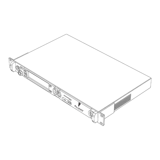
Page 26: Control Unit
Control Unit The CrewCom Control Unit (CU) is a rack-mount device built to withstand the rigors of road use and rental applications. It is the foundation for CrewNet. The CCU-44 is an 8-intercom-port CU with the ability to support (4) 2- Wire and (4) 4-Wire ports simultaneously, providing eight intercom inputs/outputs. - Page 27 E. LCD Screen: Display for viewing real-time status of system, navigating menus, and making subsequent settings adjustments. The LCD screen is the focal point of the Control Unit’s (CU) functionality. On the Home screen, the LCD displays the status of all Normal mode wireless Radio Packs that are currently paired to the CU.
-
Page 28: Ccu-44 Rear
(up to 16 TB drive size). Some operating systems (e.g., Windows 10) promote NTFS format, but only allow FAT32 formatting up to 32 GB. For help with formatting larger USB thumb drives, contact Pliant customer support at +1.334.321.1160 (option 3 for Service and Support). - Page 29 D. 2-WIRE Intercom Port (x 4): The Intercom Channel ports (1, 2, 3, and 4) allow the user to connect the Control Unit to 2-Wire external intercom systems. The XLR-3M/F 2-Wire intercom ports interface with Clear- Com, RTS, AudioCom (Balanced), and other compatible intercom systems. The pairs of XLR-3M and XLR-3F are electrically identical—including the grounds—but the grounds of the four channels are electrically isolated from each other.
- Page 30 J. SYNC IN Port (RJ-45 or Fiber): SYNC IN allows the Control Unit to receive and use a sync source (available CrewNet connection) from another CrewCom system, but this connection is not required to be part of any system configuration. This particular connection can support either an RJ-45 copper (Cat 5e or greater) port or a Single Mode Fiber (duplex LC connector) port, but not both at the same time.
- Page 31 B. 4-WIRE Intercom Port (x 2): The RJ-45 4-Wire Intercom ports (3 and 4) interface with 4-Wire intercom systems and devices. These are audio-only ports and do not support data transfer. The connector is balanced and transformer isolated. These connections do not use standard CAT-5e cables. The cables used must be wired per the CrewCom pin connections and per the device to which you are connecting (See "More About the CrewCom 4-Wire / RJ-45 Connection"...
-
Page 32: Control Unit Display
Control Unit Display Home Operating Screen Serves as the primary operating screen and displays the status of the Control Unit’s connected Radio Packs. Figure 8 Control Unit Primary Operating Screen Note: The Link Quality Indicator (LQ) provides a diagnostic measurement of actual packet transmission from Radio Pack to Radio Transceiver and vice versa. -
Page 33: Secondary Operating Screen
Secondary Operating Screen Displays additional information about the status of the Control Unit’s connected Radio Packs. Press the Home button once to toggle between the Primary and Secondary screens. After 60 seconds, the screen will time out and revert back to the Home screen. Figure 9 Control Unit Secondary Operating Screen Note: Radio Signal Strength Value displays the actual value of the radio signal in dBm. -
Page 34: Control Unit Menu
Control Unit Menu The following menu tree displays the Control Unit’s primary menu options and settings: Figure 10 Control Unit Menu Product Overview - 26... -
Page 35: Setup And Installation
CHAPTER 4 SETUP AND INSTALLATION This chapter consists of the following sections: Determine if you have a CCF. Position Devices How To Install Control Units Connect to CrewNet Power On the System How to Power On and Configure the System Upload Configuration File (CCF) Loading a CrewCom Configuration File via USB Uploading a CrewCom Configuration File via CrewWare... -
Page 36: Determine If You Have A Ccf
(If you have no configuration documentation or printed system diagram, contact the person who provided your CrewCom system for assistance or contact Pliant Customer Support.) If your CU has not been pre-configured with a CCF (and if you do not have a saved CCF on a USB drive to load to your CU), you will need to install CrewCom’s software application, CrewWare, to create one. -
Page 37: Position Devices
Position Devices After you plan your coverage area and determine if you have a CCF, you can begin positioning your Control Units (CUs), Radio Transceivers (RTs), and Hub(s) (if applicable). How To Install Control Units 1. Place the CU on a flat, dry surface, or in a desired rack-mounted location (rack screws not included). Wherever it is placed, ensure that the air input and output sections on the sides of the CU are not restricted. -
Page 38: Connect To Crewnet
NET PWR LED lighting red. In this case, one or more additional Pliant 48VDC power supplies must be used (PPS-48V-02 included with Hub; sold separately with all other devices). Fiber (Optical) Ports - For a fiber CrewNet port, a Single Mode Fiber cable (duplex LC connector) will be required (up to 32,800 ft. -
Page 39: Power On The System
Power On the System Once all desired CrewNet connections are made, power ON the CU to initiate system startup. How to Power On and Configure the System 1. If using CrewCom Hubs, verify that they are utilizing the appropriate supplied 48V local power supply. 2. -
Page 40: Upload Configuration File (Ccf)
GB drive size). Some operating systems (e.g., Windows 10) promote NTFS format, but only allow FAT32 formatting up to 32 GB. For help with formatting larger USB drives, contact Pliant customer support at +1.334.321.1160 (option 3 for Service and Support). - Page 41 2. Navigate down the list of menu options until Upload System Configuration is highlighted. Figure 11 CU LCD Upload Configuration File Prompt 3. Press the Master CU's enter button and scroll until you find the configuration file you wish to use, then press enter to select it.
-
Page 42: Uploading A Crewcom Configuration File Via Crewware
6. Once the configuration file has finished loading, the Master CU will briefly display a "CCF Upload Complete" message along with a configuration summary. Figure 14 CU LCD Configuration File Summary Screen 7. Power down the Master Control Unit when it displays the following message: “CCF Changed. Power down Master CU for 10 seconds for configuration changes to take effect.”... -
Page 43: Delete Configuration File (Ccf)
Delete Configuration File (CCF) If you plan to connect a Control Unit as a secondary or tertiary device, you should make sure that no CCF is currently saved on the CU to conflict with the one saved on the Master CU of your system. Delete a CU's CCF by doing the following: 1. -
Page 44: Add More Crewcom Devices
Add More CrewCom Devices If you need to add additional CrewCom devices (e.g., a Hub, RT, or additional Control Units) after you’ve applied your CrewCom Configuration File, you'll need to do the following: 1. Add the device(s) to your system diagram in CrewWare, then save the Configuration File change and apply the new Configuration File to your system. -
Page 45: Connecting Multiple Control Units
Connecting Multiple Control Units By default, the first Control Unit added to the CCF is automatically assigned the Master sync priority. Every CCF must contain one master Control Unit, which is set through CrewWare. Secondary and Tertiary sync priority assignments are not currently operational. -
Page 46: Pair Radio Packs
Pair Radio Packs CrewCom Radio Packs (RP) must be paired to a Control Unit (CU) before they can operate on any CrewCom system. Once RPs are paired to a CU, this process does not need to be done again unless the RP is being paired to a new or different CU (for example, after a replacement is made for repairs). - Page 47 5. Disconnect the USB cable from the RP; it will power off automatically after a few seconds. 6. Turn the RP back on and wait for it to log in to the system. When an RP is logged in, a signal indicator is visible on its Home screen.
-
Page 48: Connect And Configure Hardwire Ports
After all Radio Packs are paired to their Control Unit(s), proceed with connecting any hardwire connections to the Control Unit, if applicable. TIP: Always confirm that the non-Pliant intercom system and the CrewCom wireless system are functioning properly separately before connecting them together. -
Page 49: Name A Device
Name a Device CrewCom devices can be given a 16-character long name and an 8-character short name for display in the various CrewWare menus and diagrams. The default setting for CU Name is the device's electronic serial number. Note: This is a different procedure than editing the RP Profile's name. (See the CrewWare Manual and/or the "How to Edit a Profile"... -
Page 50: Sync Best Practices And Considerations
Sync Best Practices and Considerations Multiple CrewCom systems, in addition to CoachComm X-Systems, can be synchronized to operate properly when collocated. Pliant recommends the following best practices and considerations for syncing two CrewCom systems together. (For more on sync connections, see the Sync port description here: "CCU-44 Rear"... -
Page 51: Operation
CHAPTER 5 OPERATION This chapter consists of the following sections: Control Unit LEDs Lock the CU Front Panel Control Unit Settings Menu Naming a Control Unit Adjusting LCD Display Settings Link Quality Save Configuration File (CCF) Wired Settings Intercom Settings Menu 2-Wire Intercom Connectivity 4-Wire Intercom Connectivity Auxiliary In... - Page 52 Selecting the Local Headset Conference Changing the Local Headset Mic Gain Selecting the Local Headset Mic Type Adjusting the Local Headset Sidetone Using the Local Headset Local Headset Pinout and Wiring Local Area Network (LAN) Settings LAN Configuration via Control Unit LAN Configuration via CrewWare Call Set Up Call...
-
Page 53: Control Unit Leds
Control Unit LEDs Each LED on the rear of the Control Unit (CU) indicates a particular condition or status for the device. See the table below for details about each meaning. Control Unit's LEDs Port/LED Description CrewNet Left Green – CrewNet connection is good. LEDs Off –... -
Page 54: Lock The Cu Front Panel
Lock the CU Front Panel The Front Panel Lock function is intended to minimize the probability of unintentional adjustments to the system. The buttons and knobs on the front of the Control Unit (CU) will not function until unlocked, except for the power switch, which will power the unit off, and the Volume knob and Talk button, which will allow communication with a connected local headset. -
Page 55: Control Unit Settings Menu
Control Unit Settings Menu The Control Unit (CU) can be configured depending on user preferences. The following settings and processes can be found in the CU’s menu under Control Unit Settings. These settings can also be managed using CrewWare. (See CrewWare Manual for more information.) Naming a Control Unit... - Page 56 LCD Brightness Allows adjustment to the LCD’s brightness; select either High , Med , Low or Off for brightness level. The default setting for LCD backlight brightness is High . Figure 21 Edit Control Unit LCD Backlight Brightnes LCD Timeout Enables users to set the amount of time the LCD’s backlight will stay lit after engaging the Control Unit’s interface.
- Page 57 LED Brightness Enables users to adjust the brightness of the Control Unit LED indicators (Talk LED for local headset on front of CU). Select either High , Medium , Low , or Off . The default setting for LED brightness is High . Figure 23 Edit Control Unit LED Brightness Operation - 49...
-
Page 58: Link Quality
Link Quality The Link Quality (LQ) is a numeric value that provides a real-time metric on the quality of communication between the Radio Transceiver and the Radio Pack. The LQ serves as a diagnostic tool for proper system operation and troubleshooting Radio Packs. -
Page 59: Save Configuration File (Ccf)
Save Configuration File (CCF) Changes to the configuration during operation will be saved in real-time. However, if you wish to save a copy of the configuration file for later use, follow these procedures using CrewWare. 1. Make sure your Control Unit(s) are powered on. 2. -
Page 60: Wired Settings
Wired Settings The CrewCom wired settings can be configured depending on user preferences. The following settings and processes can be found in the CU’s menu under Wired Settings. (You can access this area of the menu by pressing the Wired button on the front of the Control Unit.) These settings can also be managed using CrewWare. - Page 61 C. Intercom Type: Allows selection from the four possible intercom types: Off, RTS, AudioCom (Balanced), and ClearCom. The below types of intercom only affect 2-Wire operation and do not control 4-Wire operation. When connecting to a 4-Wire intercom system, you must enable the port (On/Off) before using. The default setting for Intercom Type is OFF.
- Page 62 D. Call: Each wired intercom port (2-Wire only) can be individually set to send and receive a CrewCom-generated call signal to/from a connected wired intercom system. To do so, turn that port’s Call function ON . Turning the Call function OFF only prevents the signal from entering or leaving CrewCom via the respective port. Call signals can still be generated and transmitted by entities across CrewNet.
- Page 63 G. Intercom Audio In/Out: The IN level control adjusts the incoming level (from the connected wired intercom) of the currently selected wired intercom channel. If an intercom port is disabled, the IN Level control is inactive. The default setting for 2-Wire Intercom In is "−6." The default setting for 4-Wire Intercom In is "0." The OUT level control adjusts the outgoing level (from CrewCom) of the currently selected wired intercom channel.
-
Page 64: 2-Wire Intercom Connectivity
1–4 on CCU-44). Then, configure the connection either via CU or CrewWare. Configure a 2-Wire Connection via CU Always confirm that the non-Pliant 2-Wire intercom system and the CrewCom wireless system are functioning properly separately before connecting them together. Use the procedures below to configure the 2-Wire connection from the CU's Wired Settings menu. - Page 65 D. The Echo Cancellation (ECAN) setting for the 2-Wire ports is on by default. Pliant highly recommends that ECAN remain on even if a 2-Wire system is not in use. If you wish to change this setting, press Enter to view and select ON or OFF . See the Echo Cancellation section of "Intercom Settings Menu"...
-
Page 66: 4-Wire Intercom Connectivity
CCU-44). Then, configure the connection either via CU or CrewWare. Configure a 4-Wire Connection via CU Always confirm that the non-Pliant 4-Wire intercom system and the CrewCom wireless system are functioning properly separately before connecting them together. Use the procedures below to configure the 4-Wire connection from the CU's Wired Settings menu. - Page 67 4. If you need conferences for 4-Wire other than the default conferences, you will need to create new conferences in CrewWare and assign the new conferences to the wired ports. (See the CrewWare Manual for more information about creating and assigning Conferences from CrewWare.) Configure a 4-Wire Connection via CrewWare See the CrewWare Manual...
-
Page 68: Auxiliary In
Auxiliary In Aux IN (sometimes referred to as Program Audio) can be used to bring the program or other audio into the Control Unit (CU). Audio from the Aux IN connection is routed only to CrewCom devices and is not routed externally to other intercom systems. - Page 69 Aux In Connection To connect Aux IN, connect an audio source to Aux IN via the 1/4 in. (6.35 mm) TRS jack. Then, configure the connection using either the CU or CrewWare. Configure Aux In via CU Audio supplied to Aux IN can be assigned to any combination of up to 10 possible Conferences under the Control Unit's Wired Settings menu.
-
Page 70: Auxiliary Out
Auxiliary Out Audio from the Aux OUT connection can be assigned from any single Conference other than Stage Announce, but no audio sourced from the hard-wired intercom ports is routed to Aux OUT. Audio from the Aux OUT connection comes from any CrewCom audio entity such as Radio Packs and the local headset of a Control Unit (CU). - Page 71 Aux Out Connection To connect and configure Aux OUT, connect an external device to Aux OUT via the 1/4 in. (6.35 mm) TRS jack. Then, configure the connection using either the CU or CrewWare. Configure Aux Out via CU Audio supplied from Aux OUT can be assigned from any single Conference under the Wired Settings menu. The default setting for Aux OUT Level is "0."...
-
Page 72: Nulling
Nulling In order to minimize echo resulting from connection to an external 2-Wire system, it is necessary to optimize the hardware of the hybrid circuitry in the Control Unit (CU) to match line impedance. CrewCom provides a user-initiated Auto Null feature that automatically optimizes the 2-Wire interface. Nulling only impacts 2-Wire hard wired intercom connections. - Page 73 4. Select Null All to start the Auto Null process for all 2-Wire ports of the selected device. Normal functions will be interrupted for about 60 seconds during the Auto Null process (about 15 seconds per channel). An alert will display, asking you to confirm that you want to proceed.
-
Page 74: Relays
Relays CrewCom includes five General Purpose Output (GPO) contact closures for interfacing with other external devices (the Stage Announce (SA) Relay and four additional GPO relays). The user has access to both the normally open and the normally closed contacts for each relay. The rated load for all relay contacts is 0.3 Amp at 125VAC, 1 Amp at 30VDC. The following pinout is for the DA-15 connector on the rear of the Control Unit: Figure 34 Relay Pin Diagram Relay Setup... -
Page 75: Stage Announce
Stage Announce The Stage Announce (SA) function in the Control Unit (CU) is used to send a Radio Pack’s (RP) microphone signal to a dedicated external audio output. When a user activates the SA function from an assigned button on an RP, their microphone is re-routed from any selected Conferences and is sent to each connected CU's SA audio output. - Page 76 Stage Announce Setup To connect Stage Announce (SA), connect an audio destination to the SA output via the XLR-3M on the back of the Control Unit (CU). Then, configure the connection either via CU or CrewWare. Configure Stage Announce via CU Configure and set the SA audio level via the CU’s Wired Settings menu.
-
Page 77: Push A Profile
Push a Profile Each time a Radio Pack is paired to a CrewCom Control Unit, you will be prompted to select a profile to assign to that Pack. Radio Pack profiles must match the type of Radio Pack, and thus only profiles specific to the Radio Pack model being paired or used will appear in the available list. -
Page 78: Local Headset
Local Headset The following settings can be accessed by pressing the LOCAL button on the front panel of the Control Unit or by pressing Menu and navigating to Local Headset Settings . Selecting the Local Headset Conference The Control Unit headset connector is a functional user communication point, designed primarily for setup and troubleshooting. -
Page 79: Using The Local Headset
Pin 2 Mic + Pin 3 Speaker − Pin 4 Speaker + Figure 37 4-Pin XLR Male Local Headset Connection See the SmartBoom PRO and SmartBoom LITE data sheets for the pin wiring information for Pliant's SmartBoom headsets. Operation - 71... -
Page 80: Local Area Network (Lan) Settings
Local Area Network (LAN) Settings Dynamic Host Configuration Protocol (DHCP) is a system that allows each component on a computer network to automatically obtain the network address information required for Network Interface Devices to communicate with one another. The CrewCom system can utilize DHCP if it is enabled on your Local Area Network (LAN). To use DHCP, the CrewCom Control Unit will need to be configured as a DHCP client. - Page 81 TCP/IP Address In DHCP mode: take note of the Control Unit's assigned IP address from this menu, and use it to connect to CrewWare. In Manual mode, input your desired TCP/IP Address on this screen using the CU's navigation buttons. Press the CU's enter button when done to save changes.
-
Page 82: Lan Configuration Via Crewware
Default Gateway Input the appropriate Default Gateway address using the CU's navigation buttons. Figure 41 Gateway Input MAC Address Reference the MAC Address screen if needed for setting up your LAN connection. Figure 42 MAC Address Read-Only Screen Port Number The default Port value to connect to a Control Unit is 2017 . -
Page 83: Call
Call Call signals may be initiated by entities across CrewNet. Each 2-Wire intercom port may be individually set to send and receive a CrewCom-generated call signal to or from a connected wired intercom system by enabling the Call function for that port. Disabling the Call function for that port prevents the signal from leaving CrewCom via the respective port. -
Page 84: Adjusting Access Rights
Adjusting Access Rights Access rights allow customized access for specific user types. CrewCom utilizes two levels of access (Admin and User) in two ways: Software Access Rights and System Access Rights. Levels of Access CrewCom provides users with two levels of system Access Rights: Admin and User. Admin Level –... -
Page 85: Setting Passcode
3. Navigate to the appropriate menu in the device, select the setting you wish to change, and enter the system passcode one time to access that particular setting. (In this case, the device will revert back to its "locked" state when you exit the menu or when the temporary access times out.) Set System Access Level from Master Control Unit You can lock/unlock the access to your system’s device menus from the Master Control Unit menu by selecting Tech Menu and then User Rights using the CU's front-panel navigation buttons. -
Page 86: Restore Factory Defaults
Restore Factory Defaults Users can choose to restore factory defaults for the device or system. When restoring factory defaults, these settings are reset to their original factory settings: Control Unit Factory Settings Control Unit Setting Control Unit Default Reset by “Restore Defaults” CU Name (Long) ESN# CU Name (Short) -
Page 87: Product Specifications
CHAPTER 6 PRODUCT SPECIFICATIONS This chapter consists of the following sections: Control Unit Specifications Product Specifications - 79... -
Page 88: Control Unit Specifications
Control Unit Specifications Control Unit Specifications Specification* CCU-22 CCU-44 Hardwired Intercom Audio Channels Active Radio Packs 18 (requires use of 3 RTs.) No. of Paired Radio Packs Supported (per CU) USB Ports (1) USB Type A; (1) Micro USB Front Panel LCD Display 512 ×... - Page 89 2,000 m (6,562 ft.) RoHS Compliant *Notice About Specifications: While Pliant makes every attempt to maintain the accuracy of the information contained in this manual, this information is subject to change without notice, and published device/system functions and features are subject to firmware version. Please check our website for the latest system specifications and certifications.
-
Page 90: Product Support
CHAPTER 7 PRODUCT SUPPORT This chapter consists of the following sections: Product Support Returning Equipment for Repair or Maintenance Product Support - 82... -
Page 91: Product Support
All shipments of Pliant products should be made via UPS, or the best available shipper, prepaid and insured. The equipment should be shipped in the original packing carton; if that is not available, use any suitable container that is rigid and of adequate size to surround the equipment with at least four inches of shock-absorbing material. -
Page 92: System Maintenance And Storage
CHAPTER 8 SYSTEM MAINTENANCE AND STORAGE This chapter consists of the following sections: System Maintenance and Storage Cleaning Temperature and Humidity System Maintenance and Storage - 84... -
Page 93: System Maintenance And Storage
All electronic devices can be susceptible to particulate contamination. If yours are exposed to an extremely dusty environment, contact Pliant’s Customer Service for internal cleaning. Temperature and Humidity CrewCom components are designed to be very durable and can tolerate a wide range of environmental conditions;... -
Page 94: License And Compliance Information
CHAPTER 9 LICENSE AND COMPLIANCE INFORMATION This chapter consists of the following sections: License Information License and Compliance Information - 86... -
Page 95: License Information
License Information Warning: Changes or modifications to this device not expressly approved by Pliant could void the user’s authority to operate the equipment. 1. FCC Notices A. This equipment has been tested and found to comply with the limits for a Class A digital device, pursuant to part 15 of the FCC rules. -
Page 96: Warranty Information
CHAPTER 10 WARRANTY INFORMATION This chapter consists of the following sections: Warranty Information Limited Warranty Parts Limited Warranty Warranty Information - 88... -
Page 97: Warranty Information
First year of warranty included with purchase. Second year of warranty for main models (CRP, CCU, CHB, CRT) requires product registration on the Pliant web site. Register your product here: http://plianttechnologies.com/customer/account/login/ Tempest professional products carry a two-year product warranty. -
Page 98: Parts Limited Warranty
120 days from the date of sale to the end user. This warranty does not cover any defect, malfunction, or failure caused by circumstances beyond the control of Pliant Technologies, LLC, including but not limited to negligent operation, abuse, accident, failure to follow instructions in the Operating Manual, defective or improper associated equipment, attempts at modification and/or repair not authorized by Pliant Technologies, LLC, and shipping damage.
Need help?
Do you have a question about the Crewcom CCU-22 and is the answer not in the manual?
Questions and answers