Table of Contents
Advertisement
Quick Links
Advertisement
Table of Contents

Subscribe to Our Youtube Channel
Related Manuals for Pliant CREWCOM


Summary of Contents for Pliant CREWCOM
- Page 1 Control Unit OPERATING MANUAL Version 1.10...
- Page 2 - ii...
-
Page 3: Thank You
CrewCom System. In order to get the most out of your new CrewCom product, please take a few moments to read this manual completely so that you better understand the operation of this product. For questions not addressed in this manual, feel free to review the additional support documentation provided on our website (www.plianttechnologies.com) or contact Pliant’s Customer Support Department. -
Page 4: Table Of Contents
Firmware Release Notes CrewCom Overview Decentralized Network Architecture Flexible RF Platform Intuitive User Experience CrewCom Devices CrewWare CrewCom Configuration File (CCF) CrewCom Configuration File Defaults Determining Which CCF is Active Conferences Profiles Power Over CrewNet What is Power-over-CrewNet? Powering Downstream Devices... - Page 5 Connect to CrewNet Power On the System How to Power On and Configure the System Upload Configuration File (CCF) Loading a CrewCom Configuration File via USB Uploading a CrewCom Configuration File via CrewWare Delete Configuration File (CCF) Add More CrewCom Devices...
- Page 6 Change Device Names from CrewWare Synchronization of Multiple Systems What is Sync? Hopping Pattern and Frequency Band Coordination Sync CrewCom Systems Sync CrewCom to a CoachComm X-System Sync In Indicators Sync Best Practices and Considerations Operation Control Unit LEDs Lock the Control Unit Front Panel...
- Page 7 Auxiliary Out Nulling Relays Stage Announce Push a Profile Changing Profile Assignments from the Control Unit Changing Profile Assignment from the Radio Pack Changing Profile Assignments from CrewWare Local Headset Selecting the Local Headset Conference Changing the Local Headset Mic Gain Selecting the Local Headset Mic Type Adjusting the Local Headset Sidetone Using the Local Headset...
- Page 8 Control Unit Specifications Product Support Product Support Returning Equipment for Repair or Maintenance System Maintenance and Storage System Maintenance and Storage Cleaning Temperature and Humidity License and Compliance Information License Information Warranty Information Warranty Information Limited Warranty Parts Limited Warranty Table of Contents - viii...
-
Page 9: Safety Information
CHAPTER 1 SAFETY INFORMATION This chapter consists of the following sections: Control Unit Safety Information Safe Operation Recommendations Safe Installation Recommendations Power Information Safety Information - 1... -
Page 10: Control Unit Safety Information
Use only attachments/accessories that are specifically made for or certified by Pliant Technologies with the Control Unit. Any attempt to modify ports in order to use cables or wires that are not manufactured specifically for or certified for use on this system will void the product warranty. -
Page 11: Safe Installation Recommendations
Refer all Control Unit service to qualified Pliant Technologies service personnel. There are no user-serviceable parts inside the CrewCom Control Unit. Opening the product may expose dangerous electrical components, which will result in product failure. Any attempt to self-service or self-repair the unit will void the product warranty. - Page 12 AC Power Connection Safety Always connect the power cord to the CrewCom Control Unit before connecting to the outlet. CrewCom Control Units are powered by an internal power supply. The cord to connect the internal power supply to the mains supply must conform to the following specifications: The mains power cord shall have an IEC C13 connector at one end and a mains power plug at the opposite end.
-
Page 13: Introduction
Firmware Release Notes CrewCom Overview Decentralized Network Architecture Flexible RF Platform Intuitive User Experience CrewCom Devices CrewWare CrewCom Configuration File (CCF) CrewCom Configuration File Defaults Determining Which CCF is Active Conferences Profiles Power Over CrewNet What is Power-over-CrewNet? Powering Downstream Devices... -
Page 14: What's In The Box
Quick Start Guide USB Flash Drive that includes product documentation Warranty Extension Registration Card Note: A one-year product warranty is standard with CrewCom products. Follow the product registration instructions on the Warranty Extension Registration Card and visit Pliant's Product Registration Page to extend your product warranty to two years at no charge. -
Page 15: Firmware Release Notes
Firmware Release Notes Find the latest CrewCom firmware release notes on the Pliant Technologies website. Download the latest firmware release from the Pliant Technologies downloads page. Introduction - 7... -
Page 16: Crewcom Overview
Cat 5e (or greater) and/or Single Mode Fiber (SMF) connections. Flexible RF Platform CrewCom’s RF platform is vast and flexible to meet the needs of virtually any wireless communication challenge facing production and entertainment professionals worldwide. Each CrewCom wireless product is available in the 2.4GHz and 900MHz (North America, Australia, and New Zealand only) ISM... -
Page 17: Crewcom Devices
CrewCom Devices The following is a list of available CrewCom devices. For more information on each of these products and their configuration capabilities, visit the specific device's overview pages linked below. Control Unit (CU) –... -
Page 18: Crewware
CrewCom wireless system. CrewWare is used for monitoring and managing CrewCom wireless intercom systems. The software enables the user to create a CrewCom Configuration File offline and then load the settings to your system from a portable USB drive or from a connected computer. -
Page 19: Crewcom Configuration File (Ccf)
Determining Which CCF is Active The CCF that is currently active for the CrewCom system is named in the top banner of the Primary CU's main menu. The Primary CU will also have (Primary) next to the CCF name. If the system was configured using Auto Configuration, the CCF name will show as "AutoCfg."... - Page 20 Figure 1 CCF Name in CU Main Menu Figure 2 AutoCfg in CU Main Menu Figure 3 NoCfg in CU Main Menu The active CCF is also named in CrewWare above the System Diagram left-hand panel. Figure 4 CCF Name in CrewWare Introduction - 12...
-
Page 21: Conferences
Figure 5 Conferences CU Menu Item Profiles Each CrewCom Radio Pack (RP) has a Profile that contains a variety of system settings that are defined as either global profile settings or user settings. An RP Profile determines the functionality of an RP’s local controls, knobs, and buttons (including Conference assignments), and allows customization for user preferences, roaming, and operating mode. - Page 22 User Settings – A user setting is one that is classified as being adjustable by the RP user and is limited to local device settings that do not alter the CrewCom Configuration File. The Profile can be used to determine these settings, but they can also be customized directly from an RP (after a Profile is loaded), the Control Unit's (CU's) menu, or CrewWare.
-
Page 23: Power Over Crewnet
RJ-45 Copper Ports - Use the supplied 15 ft. (4.6 m) Cat 5e cable, or your own Cat 5e (or greater) cable (up to 330 ft. (100 m) in length). Any CrewCom device connected to CrewNet via a Cat 5e (or greater) cable will receive PoC from the CU via the CrewNet port. In some... - Page 24 Fiber connections will not transfer power to a CrewCom device. For CrewNet-compatible devices using fiber connectivity, local power must be supplied to that device using a Pliant 48VDC power supply (PPS-48V-02 included with Hubs, sold separately for all other devices). Once local power is supplied to the device, downstream devices may receive power via PoC (subject to limitations, depending on the line lengths and the number and configuration of those connected devices.)
-
Page 25: Operational Modes (Normal And High Density)
Operational Modes (Normal and High Density) Pliant Technologies latest CrewCom firmware and software update, Version 1.10, adds a new major feature, High Density Operational Mode. High Density Mode is a selectable mode of operation for existing hardware that will allow user densities to increase by more than fivefold. When selected, this new mode of operation will allow for up to 32 Radio Packs (RPs) to log into a single Radio Transceiver (RT). - Page 26 Figure 7 Normal Mode Figure 8 High Density Mode Introduction - 18...
-
Page 27: Product Overview
CHAPTER 3 PRODUCT OVERVIEW This chapter consists of the following sections: Control Unit CCU-44 Front CCU-44 Rear CCU-22 Control Unit Display Home Operating Screen Secondary Operating Screen Control Unit Menus Product Overview - 19... -
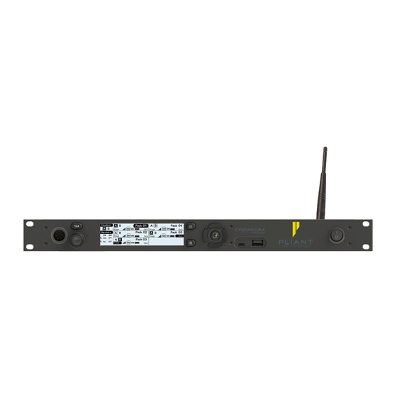
Page 28: Control Unit
Control Unit The CrewCom Control Unit (CU) is a rack-mount device built to withstand the rigors of road use and rental applications. It is the foundation for CrewNet. The CCU-44 is an 8-intercom-port CU with the ability to support (4) 2-Wire and (4) 4-Wire ports simultaneously, providing eight intercom inputs/outputs. - Page 29 E. LCD Screen: Display for viewing real-time status of system, navigating menus, and making subsequent settings adjustments. The LCD screen is the focal point of the CU functionality. On the Home screen, the LCD displays the status of all Normal Operational Mode enabled wireless Radio Packs (RPs) that are currently paired to the CU.
-
Page 30: Ccu-44 Rear
M. USB A: For RP pairing, using a USB-to-Micro-USB cable, and for updating CrewCom Configuration files (CCF) via an external USB flash drive. (See "Upload Configuration File (CCF)" on page 38 for more information.) Note: The CrewCom CU is currently compatible with FAT and FAT32 formatted USB thumb drives (up to 16 TB drive size). - Page 31 CrewNet connections are supported per CU using either two RJ-45 copper (Cat 5e or greater) ports or an RJ-45 copper and Single Mode Fiber (duplex LC connector) port. Any CrewCom device connected to CrewNet via a Cat 5e (or greater) cable will receive Power-over-CrewNet (PoC) from the CU via the CrewNet port.
- Page 32 J. SYNC IN Port (RJ-45 or Fiber): SYNC IN allows the CU to receive and use a sync source (available CrewNet connection) from another CrewCom system, but this connection is not required to be part of any system configuration. This particular connection can support either an RJ-45 copper (Cat 5e or greater) port or a Single Mode Fiber (duplex LC connector) port, but not both at the same time.
- Page 33 These are audio-only ports and do not support data transfer. The connector is balanced and transformer isolated. These connections do not use standard CAT-5e cables. The cables used must be wired per the CrewCom pin connections and per the device to which you are connecting (See "More About the CrewCom 4-Wire / RJ-45...
-
Page 34: Control Unit Display
Control Unit Display Home Operating Screen Serves as the primary operating screen and displays the status of the Control Unit’s (CU's) connected Radio Packs (RPs). Note: Currently, High Density enabled RPs do not show on the front panel of any CUs. These packs can be seen in CrewWare. -
Page 35: Secondary Operating Screen
Secondary Operating Screen Displays additional information about the status of the CU’s connected RPs. Press the Home button once to toggle between the Primary and Secondary screens. After 60 seconds, the screen will time out and revert back to the Home screen. Figure 13 Control Unit Secondary Operating Screen Note: Radio Signal Strength Value displays the actual value of the radio signal in dBm. -
Page 36: Control Unit Menus
Control Unit Menus The following menu tree displays the Control Unit’s menu options upon first power on or factory default restored: Figure 14 Control Unit First Power On Menu Product Overview - 28... - Page 37 The following menu tree displays the Control Unit’s primary menu options and settings: Figure 15 Control Unit Menu Product Overview - 29...
-
Page 38: Setup And Installation
Connect to CrewNet Power On the System How to Power On and Configure the System Upload Configuration File (CCF) Loading a CrewCom Configuration File via USB Uploading a CrewCom Configuration File via CrewWare Delete Configuration File (CCF) Add More CrewCom Devices... - Page 39 Change Device Names from CrewWare Synchronization of Multiple Systems What is Sync? Hopping Pattern and Frequency Band Coordination Sync CrewCom Systems Sync CrewCom to a CoachComm X-System Sync In Indicators Sync Best Practices and Considerations Setup and Installation - 31...
-
Page 40: Plan Coverage Area
Plan Coverage Area Before installation begins, it is a good idea to plan your coverage area so that equipment is positioned in the best possible locations. Planning Tips Map out the site and identify the most critical areas where communication is needed. Consider cable length limitations during planning. -
Page 41: Determine If You Have A Ccf
If your CU has not been pre-configured with a CCF (and if you do not have a saved CCF on a USB drive to load to your CU), you will need to either Auto Configure your system or install CrewCom’s software application, CrewWare, to create one. -
Page 42: Position Devices
Position Devices After you plan your coverage area and determine if you have a CCF, you can begin positioning your Control Units (CUs), Radio Transceivers (RTs), and Hub(s) (if applicable). How To Install Control Units 1. Place the CU on a flat, dry surface, or in a desired rack-mounted location (rack screws not included). -
Page 43: Connect To Crewnet
RJ-45 Copper Ports - Use the supplied 15 ft. (4.6 m) Cat 5e cable, or your own Cat 5e (or greater) cable (up to 330 ft. (100 m) in length). Any CrewCom device connected to CrewNet via a Cat 5e (or greater) cable will receive (PoC) via the CrewNet port. -
Page 44: Power On The System
1. Turn ON the power switch on the front of the CU. If your Control Unit (CU) was pre-configured with a CrewCom Configuration File (CCF) at the factory or other source, wait for the configuration file (CCF) to load on the system. The CU will display a progress bar during the load process. - Page 45 Configuration Troubleshooting: Once the system is powered on, you can tell that a configuration error has occurred with an RT if its TX LED is not lit. The configuration error may be present in the RT or other device upstream. You may need to connect to CrewWare to identify the specific configuration errors needing resolution.
-
Page 46: Upload Configuration File (Ccf)
Upload Configuration File (CCF) Each CrewCom system uses a configuration file (.ccf file extension) to direct the operation of all processes and data. The CCF contains hardware device configuration, Conference and Profile settings, 2-wire port and 4-wire port intercom settings, and all other CrewNet information for all connected CrewCom devices. - Page 47 If First Power On or After Factory Default Reset 1. Navigate down the list of menu options until Load Configuration is highlighted and press the primary CU's enter button. Press enter again to select Load Configuration via Flash Drive. Figure 16 CU LCD Load Configuration File via Flash Drive 2.
- Page 48 5. Once the configuration file has finished loading, the primary CU will display a "CCF Upload Complete" message along with a configuration summary. Remove the USB flash drive. Figure 19 CU LCD Configuration File Summary Screen 6. The CU will automatically reboot. Figure 20 CU LCD Reboot 7.
- Page 49 2. Plug the USB drive into the front of the primary CU. An External USB Drive menu screen will display on the CU LCD. Navigate down the list of menu options until Upload System Configuration is highlighted. Figure 21 CU LCD Upload Configuration File Prompt 3.
-
Page 50: Uploading A Crewcom Configuration File Via Crewware
7. The CU will automatically reboot. Figure 25 CU LCD Reboot 8. Upon startup, the new configuration file will load and be in use. Uploading a CrewCom Configuration File via CrewWare See the CrewWare Manual for more information about this process. -
Page 51: Delete Configuration File (Ccf)
Delete Configuration File (CCF) If you plan to connect a Control Unit (CU) as a non-primary device, you should make sure that no CCF is currently saved on the CU to conflict with the one saved on the primary CU of your system. You will either need to Restore Factory Defaults on the CU (see "Restore Factory Defaults"... -
Page 52: Add More Crewcom Devices
Add More CrewCom Devices If you need to add additional CrewCom devices (e.g., a Hub, RT, or additional CUs) after you’ve applied your CrewCom Configuration File, you'll need to do the following: Note: To add more CrewCom devices to a system that has been Auto Configured, restore factory defaults on the CU and Auto Configure again with all devices connected. -
Page 53: Connecting Multiple Control Units
Connecting Multiple Control Units Every CCF must contain one primary CU. By default, the first Control Unit (CU) added to the CCF is automatically assigned as the primary CU. Any additional CUs will need to be added through CrewWare and CCF loaded to CUs or auto configured on the non-primary CU. Up to 3 non-primary CUs can be added to a system. - Page 54 CrewNet supports up to 4 CUs. These additional CUs can be connected to the network via an available CrewNet port on another CU or a CrewCom Hub. No CU additions can be made via an RT's CrewNet or Loop ports. Multiple Control Units may only be connected together (i.e., daisy-chained) when they are connected directly from the primary CU.
- Page 55 Figure 31 Control Unit Configuration Limitations Setup and Installation - 47...
-
Page 56: Auto Configure
Note: To connect non-primary CUs, see "Add More CrewCom Devices" on page 44. Up to 3 non-primary CUs can be added to a system. See below diagrams and CrewWare Manual for more information on building system diagrams in CrewWare. - Page 57 3. The CU LCD will indicate how many RTs have been detected. Once all RTs have been detected, select OK. Figure 34 CU LCD: Radio Transceivers Detected 4. Select Yes to Auto Configure the system. Figure 35 CU LCD: Configure Radio Transceivers 5.
-
Page 58: Auto Configure Default Ccf
6. Upon completion, the CU LCD will show the message below. Select OK. Figure 37 CU LCD: Auto Configuration Complete 7. The empty CU Home screen will show. Figure 38 CU LCD: CU Primary Screen after Auto Configure 8. Continue to pair Radio Packs. See "Pair Radio Packs"... - Page 59 Figure 40 Auto Configure Default Conferences Figure 41 Auto Configure Default Profiles Setup and Installation - 51...
-
Page 60: Pair Radio Packs
CrewCom Radio Packs (RP) must be paired to a Control Unit (CU) before they can operate on any CrewCom system. Once RPs are paired to a CU, this process does not need to be done again unless the RP is being paired to a new or different CU (for example, after a replacement is made for repairs). - Page 61 2. Follow the prompts that display on the RP LCD. Your RP must match the system firmware version. The system will check that the RP firmware version is compatible. If it is not, disconnect the RP and update its firmware using CrewWare and connection to your PC.
- Page 62 Note: Remember that only 18 RPs can be actively used per CU in Normal Mode and only 64 in High Density Mode. Additional RPs can be paired to a CU, but only 18 (in Normal Mode) and 64 (in High Density Mode) may be active at a time. In multi-CU systems, take care to pair a maximum of 18 RPs (Normal Mode) or 64 RPs (High Density Mode) to each of the CUs.
-
Page 63: Connect And Configure Hardwire Ports
After all Radio Packs are paired to their Control Unit(s), proceed with connecting any hardwire connections to the CU, if applicable. TIP: Always confirm that the non-Pliant intercom system and the CrewCom wireless system are functioning properly separately before connecting them together. -
Page 64: Name A Device
Name a Device CrewCom devices can be given a 16-character long name and an 8-character short name for display in the various CrewWare menus and diagrams. The default setting for CU Name is the device's electronic serial number. Note: This is a different procedure than editing the RP Profile's name. (See the... -
Page 65: Synchronization Of Multiple Systems
All complex digital systems require synchronization of the various elements for proper operation. In the Pliant Technologies CrewCom system, this is accomplished via a sync packet that is transmitted at regular intervals by the primary Control Unit and is consequently received by all other devices on a proprietary network (CrewNet.) This sync packet contains critical information for each device to be... -
Page 66: Sync Crewcom Systems
CrewNet network topology. However, only one system should ever serve as the sync source while others will receive the sync signal via the “Sync In” port on the rear of a CU. To sync two CrewCom systems, follow the instructions below. - Page 67 The “Sync In” port can support either an RJ-45 copper (Cat 5e or greater) port or a Single Mode Fiber (duplex LC connector) port, but not both at the same time. See the images below for examples of sync connections between CrewCom systems. Figure 43 CrewCom Control Unit as Sync Source via Cat 5e...
-
Page 68: Sync Crewcom To A Coachcomm X-System
X-Systems are in use. If you are a CrewCom user planning to operate at a college or high school football game, it is highly recommended you reach out to the Home team prior to the event and determine what type of system they use for their coaches’... -
Page 69: Sync Best Practices And Considerations
Figure 48 Sync In Indicator on Top Right Sync Best Practices and Considerations Multiple CrewCom systems, in addition to CoachComm X-Systems, can be synchronized to operate properly when collocated. Pliant recommends the following best practices and considerations for syncing two CrewCom systems together. - Page 70 Sync (CrewNet) Input. CrewCom CRTs should be as far from the X-System as their application needs will allow. At a minimum, CRTs should not be located within or behind the designated team box on either sideline.
-
Page 71: Operation
CHAPTER 5 OPERATION This chapter consists of the following sections: Control Unit LEDs Lock the Control Unit Front Panel Control Unit Settings Menu Naming a Control Unit Adjusting LCD Display Settings Link Quality Save Configuration File (CCF) Wired Settings Intercom Settings Menu 2-Wire Intercom Connectivity 4-Wire Intercom Connectivity Auxiliary In... - Page 72 Selecting the Local Headset Conference Changing the Local Headset Mic Gain Selecting the Local Headset Mic Type Adjusting the Local Headset Sidetone Using the Local Headset Local Headset Pinout and Wiring Local Area Network (LAN) Settings LAN Configuration via Control Unit LAN Configuration via CrewWare Call Set Up Call...
-
Page 73: Control Unit Leds
Control Unit LEDs Each LED on the rear of the Control Unit (CU) indicates a particular condition or status for the device. See the table below for details about each meaning. Control Unit's LEDs Port/LED Description CrewNet Left Green – CrewNet connection is good. LEDs Off –... -
Page 74: Lock The Control Unit Front Panel
Lock the Control Unit Front Panel The Front Panel Lock function is intended to minimize the probability of unintentional adjustments to the system. The buttons and knobs on the front of the Control Unit (CU) will not function until unlocked, except for the power switch, which will power the unit off, and the Volume knob and Talk button, which will allow communication with a connected local headset. -
Page 75: Control Unit Settings Menu
Control Unit Settings Menu The Control Unit (CU) can be configured depending on user preferences. The following settings and processes can be found in the CU’s menu under Control Unit Settings. These settings can also be managed using CrewWare. (See the CrewWare Manual for more information.) Naming a Control Unit... - Page 76 LCD Timeout Enables users to set the amount of time the LCD’s backlight will stay lit after engaging the CU’s interface. Select either 60, 30, or 10 seconds or disable the backlight timer entirely by selecting Disabled. The default setting for LCD backlight time out is Disabled. Figure 51 Edit Control Unit LCD Backlight Time Out LED Brightness Enables users to adjust the brightness of the CU LED indicators (Talk LED for local headset on front of...
-
Page 77: Link Quality
0 being the least. With CrewCom, the receiving LQ signal is reported for both the RT and RP. The RP’s on-screen LQ indicator with the box around it is the RT’s LQ from the RP. If this LQ is lower than you typically experience in normal operation, then it is an indication that you may have an issue related to interference, the transceiver, or a cable connection. -
Page 78: Save Configuration File (Ccf)
Save Configuration File (CCF) Changes to the configuration during operation will be saved in real-time. However, if you wish to save a copy of the configuration file for later use, follow these procedures using CrewWare. 1. Make sure your Control Unit(s) are powered on. 2. -
Page 79: Wired Settings
Wired Settings The CrewCom wired settings can be configured depending on user preferences. The following settings and processes can be found in the Control Unit's (CU’s) menu under Wired Settings. (You can access this area of the menu by pressing the Wired button on the front of the CU.) Tip: These settings can also be managed using CrewWare. - Page 80 C. Intercom Type: Allows selection from the four possible intercom types: Off, RTS, AudioCom (Balanced), and ClearCom. The below types of intercom only affect 2-Wire operation and do not control 4-Wire operation. When connecting to a 4-Wire intercom system, you must enable the port (On/Off) before using.
- Page 81 Call function ON. Turning the Call function OFF only prevents the signal from entering or leaving CrewCom via the respective port. Call signals can still be generated and transmitted by entities across CrewNet. The default setting for Call is OFF. See "Call"...
- Page 82 IN Level control is inactive. The default setting for 2-Wire Intercom In is "0." The default setting for 4-Wire Intercom In is "0." The OUT level control adjusts the outgoing level (from CrewCom) of the currently selected wired intercom channel. If an intercom port is disabled, the OUT Level control is inactive. The default setting for 2-Wire Intercom Out is "0."...
-
Page 83: 2-Wire Intercom Connectivity
CCU-22 and labeled 1–4 on CCU-44). Then, configure the connection either via CU or CrewWare. Configure a 2-Wire Connection via Control Unit Always confirm that the non-Pliant 2-Wire intercom system and the CrewCom wireless system are functioning properly separately before connecting them together. Use the procedures below to configure the 2-Wire connection from the CU's Wired Settings menu. - Page 84 Enter when the desired setting is highlighted. Determine if you would like to send and receive Call signals from CrewCom to the connected 2-Wire intercom system. Press Enter to view and select ON or OFF. See the Call section of "Intercom Settings Menu"...
- Page 85 Configure a 2-Wire Connection via CrewWare See the CrewWare Manual for more information about this process. Operation - 77...
-
Page 86: 4-Wire Intercom Connectivity
5–8 on CCU-44). Then, configure the connection either via CU or CrewWare. Configure a 4-Wire Connection via Control Unit Always confirm that the non-Pliant 4-Wire intercom system and the CrewCom wireless system are functioning properly separately before connecting them together. Use the procedures below to configure the 4-Wire connection from the CU's Wired Settings menu. - Page 87 CrewCom utilizes RJ-45 jacks for connection to a 4-Wire port. Only two pairs of wires are utilized—one to send audio and one to receive audio. Any twisted pair wiring can be used to connect between the 4-Wire and the CrewCom system. See the table below for a list of the 4-Wire RJ-45 pin connection list.
- Page 88 4-Wire RJ-45 Connections RJ-45 Pin # CrewCom 4-Wire Pin # Pin 6 Audio Output (-) Pin 7 Pin 2 Pin 8 Pin 1 Operation - 80...
-
Page 89: Auxiliary In
Aux IN (sometimes referred to as Program Audio) can be used to bring the program or other audio into the Control Unit (CU). Audio from the Aux IN connection is routed only to CrewCom devices and is not routed externally to other intercom systems. - Page 90 Aux In Connection To connect Aux IN, connect an audio source to Aux IN via the 1/4 in. (6.35 mm) TRS jack. Then, configure the connection using either the CU or CrewWare. Configure Aux In via Control Unit Audio supplied to Aux IN can be assigned to any combination of up to 10 possible Conferences under the CU's Wired Settings menu.
-
Page 91: Auxiliary Out
Announce, but no audio sourced from the hard-wired intercom ports is routed to Aux OUT. Audio from the Aux OUT connection comes from any CrewCom audio entity such as Radio Packs (RPs) and the local headset of a Control Unit (CU). The default setting for Aux OUT Level is "0." Conference assignment changes and level adjustments can be performed via CU menu or CrewWare. - Page 92 Aux Out Connection To connect and configure Aux OUT, connect an external device to Aux OUT via the 1/4 in. (6.35 mm) TRS jack. Then, configure the connection using either the CU or CrewWare. Configure Aux Out via Control Unit Audio supplied from Aux OUT can be assigned from any single Conference under the Wired Settings menu.
-
Page 93: Nulling
During the Auto Null process, the CU LCD will display each 2-Wire port’s resistance (R), inductance (L), capacitance (C) and amplitude. There are two options for auto nulling your CrewCom system – Null All and Null by Port. The following steps detail how to initiate the Auto Null process from the CU: 1. - Page 94 An alert will display, asking you to confirm that you want to proceed. Auto Null with CrewCom will send a mic kill signal to connected AudioCom and RTS wired systems, but not to Clear-Com wired systems. Auto Null operation will mute the audio from CrewCom RPs as it connects to connected wired systems;...
-
Page 95: Relays
Relays CrewCom includes five General Purpose Output (GPO) contact closures for interfacing with other external devices (the Stage Announce (SA) Relay and four additional GPO relays). The user has access to both the normally open and the normally closed contacts for each relay. The rated load for all relay contacts is 0.3 Amp at 125VAC, 1 Amp at 30VDC. -
Page 96: Stage Announce
Stage Announce The Stage Announce (SA) function in the Control Unit (CU) is used to send a Radio Pack’s (RP) microphone signal to a dedicated external audio output. When a user activates the SA function from an assigned button on an RP, their microphone is re-routed from any selected Conferences and is sent to each connected CU's SA audio output. - Page 97 Stage Announce Setup To connect Stage Announce (SA), connect an audio destination to the SA output via the XLR-3M on the back of the CU. Then, configure the connection either via CU or CrewWare. Configure Stage Announce via Control Unit Configure and set the SA audio level via the CU’s Wired Settings menu. Figure 65 Stage Announce Settings Configure Stage Announce via CrewWare See the...
-
Page 98: Push A Profile
Push a Profile Each time a Radio Pack (RP) is paired to a CrewCom Control Unit (CU), you will be prompted to select a profile to assign to that Pack. RP profiles must match the type of RP, and thus only profiles specific to the RP model being paired or used will appear in the available list. -
Page 99: Local Headset
Local Headset The following settings can be accessed by pressing the Local button on the front panel of the Control Unit (CU)or by pressing Menu and navigating to Local Headset Settings. Selecting the Local Headset Conference The CU headset connector is a functional user communication point, designed primarily for setup and troubleshooting. -
Page 100: Using The Local Headset
Talk and Volume Controls for the headset are located to the right of the connector. A white “TALK” LED will illuminate when the mic is enabled. CrewCom uses an intelligent latching method for Talk buttons. Quickly pressing and releasing Talk will cause the mic button to latch. The white “TALK”... -
Page 101: Local Area Network (Lan) Settings
Local Area Network (LAN). To use DHCP, the CrewCom Control Unit (CU) will need to be configured as a DHCP client. If DHCP is not enabled on your LAN, then the CrewCom system can be configured to use static IP Addresses. After the CrewCom system is fully booted-up, and the CU is assigned an IP Address (either through DHCP or manually), CrewWare can connect to the CU. - Page 102 TCP/IP Address In DHCP mode: take note of the CU's assigned IP address from this menu, and use it to connect to CrewWare. In Manual mode, input your desired TCP/IP Address on this screen using the CU's navigation buttons. Press the CU's enter button when done to save changes. Figure 68 TCP/IP Address Input Subnet Mask Input the appropriate Subnet Mask address using the CU's navigation buttons.
-
Page 103: Lan Configuration Via Crewware
MAC Address Reference the MAC Address screen if needed for setting up your LAN connection. Figure 71 MAC Address Read-Only Screen Port Number The default Port value to connect to a CU is 2017. This setting is not currently viewable from the CU menu, but it is visible from CrewWare. -
Page 104: Call
Set Up Call Each CU wired intercom port (2-Wire only) can be individually set to send and receive a CrewCom- generated call signal to/from a connected wired intercom system. To do so, turn that port’s Call function ON. Turning the Call function OFF only prevents the signal from entering or leaving CrewCom via the respective port. -
Page 105: Adjusting Access Rights
CU and RP menus are "view only" when the system is locked (i.e., set to "User Level"). A user who wishes to make a CrewCom Settings change to a locked system can choose one of three options: 1. -
Page 106: Setting Passcode
3. Navigate to the appropriate menu in the device, select the setting you wish to change, and enter the system passcode one time to access that particular setting. (In this case, the device will revert back to its "locked" state when you exit the menu or when the temporary access times out.) Set System Access Level from Primary Control Unit You can lock/unlock the access to your system’s device menus from the primary CU menu by... -
Page 107: Restore Factory Defaults
Restore Factory Defaults Users can choose to restore factory defaults for the device or system. When restoring factory defaults, these settings are reset to their original factory settings: Control Unit Factory Settings Control Unit Setting Control Unit Default Reset by “Restore Defaults” CU Name (Long) CCU_xx_01 CU Name (Short) - Page 108 Note: Restoring CU factory defaults, as well as clearing an RP's memory, erases RP pairing information. If you have saved the CCF (See "Save Configuration File (CCF)" on page 70), the pairing is still visible in the CCF. For information about clearing RP memory, see the RP Manual.
-
Page 109: Product Specifications
CHAPTER 6 PRODUCT SPECIFICATIONS This chapter consists of the following sections: Control Unit Specifications Product Specifications - 101... -
Page 110: Control Unit Specifications
Control Unit Specifications Control Unit Specifications Specification* CCU-22 CCU-44 Hardwired Intercom Audio Channels Active Radio Packs (per Normal Operational Mode: 18 (requires use of at least 3 RTs.) High Density Operational Mode: 64 (requires use of at least 2 RTs.) Total No. - Page 111 2,000 m (6,562 ft.) RoHS Compliant *Notice About Specifications: While Pliant makes every attempt to maintain the accuracy of the information contained in this manual, this information is subject to change without notice, and published device/system functions and features are subject to firmware version. Please check our website for the latest system specifications and certifications.
-
Page 112: Product Support
CHAPTER 7 PRODUCT SUPPORT This chapter consists of the following sections: Product Support Returning Equipment for Repair or Maintenance Product Support - 104... -
Page 113: Product Support
Return Material Authorization Number will ensure that your equipment is handled promptly. All shipments of Pliant products should be made via UPS, or the best available shipper, prepaid and insured. The equipment should be shipped in the original packing carton; if that is not available, use any suitable container that is rigid and of adequate size to surround the equipment with at least four inches of shock-absorbing material. -
Page 114: System Maintenance And Storage
CHAPTER 8 SYSTEM MAINTENANCE AND STORAGE This chapter consists of the following sections: System Maintenance and Storage Cleaning Temperature and Humidity System Maintenance and Storage - 106... -
Page 115: System Maintenance And Storage
System Maintenance and Storage Cleaning Generally, the CrewCom hardware should be cleaned only with a dry cloth. A soft cloth with rubbing alcohol may be used to wipe the devices if needed, but you should avoid using rubbing alcohol on plastic components. -
Page 116: License And Compliance Information
CHAPTER 9 LICENSE AND COMPLIANCE INFORMATION This chapter consists of the following sections: License Information License and Compliance Information - 108... -
Page 117: License Information
Cet appareillage numérique de la classe A répond à toutes les exigencies de l’interférence canadienne causant des règlements d’équipment. 3. South Korea Notices A. The CrewCom Control Unit (CCU-22, CCU-44) complies with EMC requirement KN 32/35 and is labeled with the KC mark and RRA (Radio Research Agency) registration number. -
Page 118: Warranty Information
CHAPTER 10 WARRANTY INFORMATION This chapter consists of the following sections: Warranty Information Limited Warranty Parts Limited Warranty Warranty Information - 110... -
Page 119: Warranty Information
Warranty Information Limited Warranty Subject to the conditions of this Limited Warranty, CrewCom and MicroCom products are warranted to be free from defects in materials and workmanship for a period of two years from the date of sale to the end user, under the following conditions: First year of warranty included with purchase. - Page 120 ANY AND ALL IMPLIED WARRANTIES, INCLUDING THE IMPLIED WARRANTY OF MERCHANTABILITY, ARE LIMITED TO THE DURATION OF THIS EXPRESS LIMITED WARRANTY. NEITHER PLIANT TECHNOLOGIES, LLC NOR ANY AUTHORIZED RESELLER WHO SELLS PLIANT PROFESSIONAL INTERCOM PRODUCTS IS LIABLE FOR INCIDENTAL OR CONSEQUENTIAL DAMAGES OF ANY KIND.
-
Page 121: Parts Limited Warranty
Parts Limited Warranty Replacement parts for Pliant Technologies, LLC products are warranted to be free from defects in materials and workmanship for 120 days from the date of sale to the end user. This warranty does not cover any defect, malfunction, or failure caused by circumstances beyond the...
Need help?
Do you have a question about the CREWCOM and is the answer not in the manual?
Questions and answers