Table of Contents
Advertisement
Quick Links
Advertisement
Table of Contents

Related Manuals for TA Instruments TMA 2940


Summary of Contents for TA Instruments TMA 2940
- Page 1 Instruments Thermal Analysis & Rheology UBSIDIARY OF ATERS ORPORATION TMA 2940 Thermomechanical Analyzer Operator’s Manual PN 925615.001 Rev. D (Text and Binder) PN 925615.002 Rev. D (Text Only) Issued November 1999 TA I TMA 2940 NSTRUMENTS...
- Page 2 Notice TA I TMA 2940 NSTRUMENTS...
-
Page 3: Table Of Contents
Electrical Safety ........xiii Handling Liquid Nitrogen ....xiii Lifting the Instrument ......xvi Using This Manual ........xvii CHAPTER 1: Introducing the TMA 2940 ..........1-1 Introduction..........1-3 Components .......... 1-3 The 2940 Instrument ........1-5 2940 Display ........1-7 2940 Keypad ........ - Page 4 Table of Contents (continued) CHAPTER 2: Installing the TMA 2940..........2-1 Unpacking/Repacking the TMA 2940 ..2-3 Unpacking the TMA ......2-3 Removing the Shipping Material ..2-6 Repacking the 2940 ......2-8 Installing the Instrument ......2-9 Inspecting the System......2-9 Choosing a Location ......
- Page 5 Force Calibration ........3-5 Probe Calibration ......... 3-6 Temperature Calibration ...... 3-7 Cell Constant ........3-9 Running a TMA Experiment ....3-10 Experimental Procedure ..... 3-10 Selecting a Probe ........ 3-11 Zeroing the Auto Measure System ..3-12 TA I TMA 2940 NSTRUMENTS...
- Page 6 Using a Purge Gas ....... 3-18 Suggestions ......3-18 Starting an Experiment ....... 3-20 Stopping an Experiment ..... 3-20 Removing Samples ...... 3-20 Subambient Experiments ......3-22 Performing a Cooling Experiment ..3-22 Techniques for Improved Subambient Operation......3-23 TA I TMA 2940 NSTRUMENTS...
- Page 7 Sample Preparation ......4-12 Using the Aluminum Balls ..4-12 Using the Stainless Steel Clamps ........ 4-14 Flexure Accessory ........4-17 Description ......... 4-17 Accessory Installation ......4-18 Calibration .......... 4-18 Sample Preparation ......4-19 TA I TMA 2940 NSTRUMENTS...
- Page 8 Accessory Installation ......4-29 Calibration .......... 4-30 Sample Preparation ......4-31 Sample Encapsulating Press ..4-31 Preparing Moldable Powders ..4-35 Preparing Resinous Materials ..4-38 Preparing Sheet Materials.... 4-40 Sample Loading ......... 4-41 Cleanup ........4-42 TA I TMA 2940 VIII NSTRUMENTS...
- Page 9 Table of Contents (continued) Calculations ........4-43 Hemispherical Probe ......... 4-47 CHAPTER 5: Technical Reference ........... 5-1 Description of the TMA 2940 ....5-3 Uses of Thermomechanical Analysis ....5-4 Calculating the Coefficient of Expansion ..... 5-5 Method Considerations ....... 5-6 Status Codes ..........
- Page 10 Replacements ........6-8 Installing a New Thermocouple ..6-8 Diagnostics ..........6-9 Fuses ............. 6-9 Power Failures........6-10 TMA 2940 Test Functions......6-12 The TMA Confidence Test ....6-12 Replacement Parts ........6-15 APPENDIX A: Ordering Information ..........A-1 INDEX ............I-1...
-
Page 11: Notes, Cautions, And Warnings
Emphasizes a procedure that may damage CAUTION: equipment or cause loss of data if not followed correctly. Marks a procedure that may be hazardous to WARNING the operator or to the environment if not followed correctly. TA I TMA 2940 NSTRUMENTS... -
Page 12: Safety
Please heed the warning labels and take the necessary precautions when dealing with those parts of the instrument. The TMA 2940 Operator's Manual contains cautions and warnings that must be followed for your own safety. -
Page 13: Electrical Safety
Refer to the NOTE on page 2-11 for the method of drying out the equipment before use. Handling Liquid Nitrogen The TMA 2940 can use the cryogenic (low- temperature) agent, liquid nitrogen, for cooling in subambient experiments. Because of its low temperature (-195°C), liquid nitrogen will burn the skin. - Page 14 1. Flood the area (skin or eyes) with large quantities of cool water IMMEDIATELY; then apply cold compresses. 2. See a doctor IMMEDIATELY if the skin is blistered or if there is a chance of eye infection. TA I TMA 2940 NSTRUMENTS...
- Page 15 Please refer to the “Safety” section of the TA Instru- ments Liquid Nitrogen Cooling Accessory manual for more de- tailed instructions regarding the use of the LNCA. TA I TMA 2940 NSTRUMENTS...
-
Page 16: Lifting The Instrument
Lifting the Instrument The TMA 2940 is a fairly heavy instrument. In order to avoid injury, particularly to the back, please follow this advice: Use two people to lift and/or carry the WARNING instrument. The instrument is too heavy for one person to handle safely. -
Page 17: Using This Manual
Using This Manual CHAPTER 1 Introduces the TMA 2940 and lists its specifications. CHAPTER 2 Describes how to install and assemble your TMA 2940. CHAPTER 3 Describes routine opera- tion of the TMA instru- ment, including subambi- ent operations. CHAPTER 4... - Page 18 TA I TMA 2940 XVIII NSTRUMENTS...
- Page 19 CHAPTER 1: Introducing the TMA 2940 Introduction..........1-3 Components .......... 1-3 The 2940 Instrument ........1-5 2940 Display ........1-7 2940 Keypad ........1-7 HEATER Switch ......1-11 POWER Switch ......1-11 Accessories ..........1-12 Standard Accessories ......1-12 Optional Accessories ......1-13 Specifications ..........
- Page 20 Introduction 1–2 TA I TMA 2940 NSTRUMENTS...
-
Page 21: Introduction
The Thermomechanical Analyzer (TMA) 2940 is an analytical instrument used to test the physical properties of many different materials. The TMA 2940 works in conjunction with a TA Instruments controller and associated software to make up a themal analysis system. -
Page 22: The Tma 2940
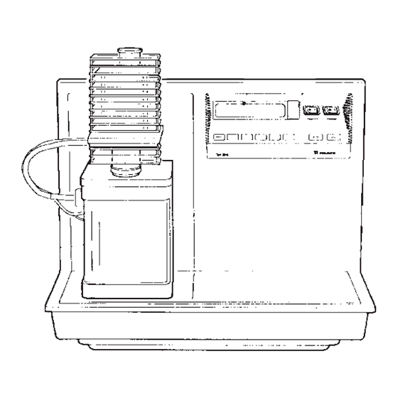
• The Chromel/Alumel sample thermocouple senses the temperature of the sample and relays the reading to the instrument. Instrument Instrument Keypad Display Furnace Enclosure Cabinet Balance Enclosure Figure 1.1 The TMA 2940 Instrument 1–4 TA I TMA 2940 NSTRUMENTS... -
Page 23: The 2940 Instrument
The 2940 Instrument The 2940 Instrument The TMA 2940 instrument contains the elec- tronics and software needed to perform experi- ments and store the results. The battery backed- up memory in the cabinet saves parameters vital to system operations if power is interrupted. - Page 24 The cabinet contains the keypad, used to control the mechanical movements of the instrument, and the display, used to observe the status of the instrument. Standby 23.25°C DimChg 0.135µm TMA 2940 Thermomechanical Analyzer Figure 1.2 TMA 2940 Keypad and Display 1–6 TA I TMA 2940 NSTRUMENTS...
-
Page 25: 2940 Display
The instrument keypad (Figure 1.2) contains the keys found in Table 1.1 on the next page and the HEATER and POWER switches. Experiment and instrument constants are entered NOTE: from the controller keyboard, not the instrument keypad. TA I TMA 2940 1–7 NSTRUMENTS... - Page 26 Introduction Table 1.1 TMA 2940 Keypad Functions Key/Function Explanation SCROLL Scrolls the realtime signals shown on the bottom line of the display. ZERO Initializes the auto- LENGTH measure system. This operation should be performed any time the probe or stage is changed.
- Page 27 START Initiates the experiment on the TMA after check- ing the program method against the mode type. This is the same function as Start on the controller. (table continued) TA I TMA 2940 1–9 NSTRUMENTS...
- Page 28 Introduction Table 1.1 TMA 2940 Keypad Functions (continued) Key/Function Explanation STOP If an experiment is running, this key ends the method normally, as though it had run to completion; i.e., the method-end conditions go into effect and the data that has been generated is saved.
-
Page 29: Heater Switch
POWER Switch The POWER on/off switch turns the power to the instrument on and off (see Figure 1.2). TA I TMA 2940 1–11 NSTRUMENTS... -
Page 30: Accessories
The TMA 2940 can perform experiments on several different types of samples using both standard and optional accessories. Standard Accessories The accessory kit supplied with the TMA 2940 contains weights, sample holder (stage), a hex wrench, tweezers, samples for calibration, and standard probes. -
Page 31: Optional Accessories
Accessories Figure 1.3 TMA Standard Probes Optional Accessories You can purchase extra items to use with your TA Instruments TMA. These optional accesso- ries will allow you to perform experiments on different types of samples: • Film/Fiber Accessory • Dilatometer Accessory •... -
Page 32: Specifications
Introduction Specifications Tables 1.2 and 1.3 contain information about the TMA’s specifications and temperature control. Table 1.2 TMA 2940 Instrument Specifications Dimensions Depth 45.5 cm (18 in.) Width 58.5 cm (23 in.) Height 66 cm (26 in.) Weight (approx.) 18 kg (60 lb) - Page 33 Specifications Table 1.3 Temperature Control Programmed 0.01 to 200 C/min heating rate Temperature reproducibility TA I TMA 2940 1–15 NSTRUMENTS...
- Page 34 Introduction 1–16 TA I TMA 2940 NSTRUMENTS...
-
Page 35: Chapter 2: Installing The Tma 2940
CHAPTER 2: Installing the TMA 2940 Unpacking/Repacking the TMA 2940 ..2-3 Unpacking the TMA ......2-3 Removing the Shipping Material ..2-6 Repacking the 2940 ......2-8 Installing the Instrument ......2-9 Inspecting the System......2-9 Choosing a Location ......2-10 Installing the Thermocouple .... - Page 36 Installation 2–2 TA I TMA 2940 NSTRUMENTS...
-
Page 37: Unpacking/Repacking The Tma 2940
Unpacking the TMA Refer to Figures 2.1 to 2.3 while unpacking your instrument. Have an assistant help you unpack this unit. WARNING Do not attempt to do this alone. Figure 2.1 Shipping Boxes TA I TMA 2940 2–3 NSTRUMENTS... - Page 38 Someone must hold onto the unit at all times while it is in this position. While your assistant holds the unit, remove the two nuts and washers from the other side. 2–4 TA I TMA 2940 NSTRUMENTS...
- Page 39 9. Have your assistant lift one side of the unit while you install two of the mounting feet (see Figure 2.3). Rotate the unit and install the two remaining mounting feet in the same manner. Figure 2.3 Installing the Mounting Feet TA I TMA 2940 2–5 NSTRUMENTS...
-
Page 40: Removing The Shipping Material
Installation Removing the Shipping Material The TMA 2940 has been specially packed to prevent damage to delicate parts. To unpack the instrument follow these steps: Steps 1-9 may be completed by the customer. CAUTION: Only qualified service personnel should proceed with steps 10-19. - Page 41 12. Inspect the suspension components (wires and springs) for damage. 13. Remove the shipping foam at the rear of the balance assembly by pulling upward. TA I TMA 2940 2–7 NSTRUMENTS...
-
Page 42: Repacking The 2940
19. Check the force calibration (see the instru- ment control online documentation for details). Repacking the 2940 To pack and ship your instrument, use the hardware retained during unpacking and reverse the instructions found on pages 2-3 to 2-8. 2–8 TA I TMA 2940 NSTRUMENTS... -
Page 43: Installing The Instrument
Installing the Instrument Installing the Instrument Before shipment the TMA 2940 instrument is inspected both electrically and mechanically, so that it is ready for operation after it has been installed. Installation involves the following procedures described in detail in this chapter: •... -
Page 44: Choosing A Location
Installation If the instrument is intact but parts are missing, contact TA Instruments. A list of TA Instruments offices can be found in Appendix A of this manual. Choosing a Location Because of the sensitivity of TMA experiments, it is important to choose a location for the instrument using the following guidelines: In . -
Page 45: Installing The Thermocouple
Ramp at 10°C/min to 400°C Isothermal for 30 min. Installing the Thermocouple Your TMA 2940 will arrive without a sample thermocouple installed. With the balance enclosure removed and the furnace raised, follow these steps: 1. Insert the two-pin, color-coded thermo- couple connector into the fitting as shown in Figure 2.5. - Page 46 5. Slide the balance enclosure into position. 6. Replace the screws, two on each side, that hold the balance enclosure in place. 7. Install the weight tray door as instructed in the next section. 2–12 TA I TMA 2940 NSTRUMENTS...
-
Page 47: Installing The Weight Tray Door
4. Push down gently on the door as you guide the upper hole over the cone-shaped post at the top of the entrance. 5. Release the door and close it. 6. Install the stage as directed in the next section. TA I TMA 2940 2–13 NSTRUMENTS... -
Page 48: Installing The Stage
Installation Installing the Stage To install the stage on the TMA 2940, check to make sure the furnace is raised and off to the side, then follow these steps (refer to Figure 2.7 for illustration of the parts): 1. Remove the stage shield by lifting it straight up. - Page 49 It should be close to, but not touching the sample. b. Hold the thermocouple against the stage assembly and put on the spring clip to hold the thermocouple in place (see Figure 2.8). TA I TMA 2940 2–15 NSTRUMENTS...
- Page 50 Thermocouple to the Stage 11. Put the stage shield on the stage, aligning the slot in the bottom over the thermocouple wires (see Figure 2.9). 12. Rotate the furnace into position over the stage. 2–16 TA I TMA 2940 NSTRUMENTS...
- Page 51 Stage Shield Thermocouple Wires Figure 2.9 Assembled TMA with Stage and Thermocouple 13. Install one of the probes as directed in the next section. (Refer to Chapter 3 for guidelines in selecting a probe.) TA I TMA 2940 2–17 NSTRUMENTS...
-
Page 52: Installing The Expansion/Penetration Probes
Installation Installing the Expansion/ Penetration Probes When you first receive the TMA 2940, a probe will need to be installed. Later, if a different sample form is used, you can change to the appropriate probe for the experiment. (Refer to Chapter 3 for details on probe selection.) The... -
Page 53: Removing A Probe
3. Unscrew the locking lever by turning it counterclockwise approximately one turn. 4. Raise the probe gently and twist slightly to aid its removal from the stage opening. TA I TMA 2940 2–19 NSTRUMENTS... -
Page 54: Connecting Cables, Gas Lines, And Isolation Transformer
3. Tighten the hold-down screws on the connector. 4. Connect the other end of the GPIB cable to the controller or to the GPIB cable of another TA Instruments instrument con- nected to the controller. 2–20 TA I TMA 2940... - Page 55 (see Table 2.1). Figure 2.12 shows a instru- ment address of 7. If you have a multiple instruments system, each NOTE: instrument must have a different address. TA I TMA 2940 2–21 NSTRUMENTS...
- Page 56 0 0 0 1 1 0 0 1 0 0 0 0 1 0 1 0 0 1 1 0 0 0 1 1 1 0 1 0 0 1 * 0 = OFF; 1 = ON 2–22 TA I TMA 2940 NSTRUMENTS...
-
Page 57: Purge Line
The purge gas flows through the instrument and is channeled internally to the sample purge line shown in the figure on the next page. TA I TMA 2940 2–23 NSTRUMENTS... - Page 58 4. The recommended setting for the purge rate is 100 mL per minute (–100°C and above) and 200 mL/minute (–150°C and above). Figure 2.14 Air Cool and Sample Purge Lines 2–24 TA I TMA 2940 NSTRUMENTS...
-
Page 59: Air Cool Line
2. Make sure your compressed lab air source is dry, filtered, and regulated to between 175 kPa (25 psi) and 840 kPa (120 psi). 3. Connect a compressed air line to the COOL- ING GAS fitting. TA I TMA 2940 2–25 NSTRUMENTS... -
Page 60: Power Cable
Connect all other cables and gas lines before connecting the power cable to a wall outlet. 1. Make sure the instrument POWER switch (see Figure 2.16) is in the OFF (O) position. TMA 2940 Thermomechanical Analyzer Figure 2.16 Front Panel of TMA Showing POWER Switch 2. -
Page 61: Isolation Transformer
These cables accommodate different versions of the transformer and TMA cabinet and can only be connected one way for each combination. See the illustration on the next page. TA I TMA 2940 2–27 NSTRUMENTS... - Page 62 Installation Figure 2.17 Isolation Transformer Cable Connections 2–28 TA I TMA 2940 NSTRUMENTS...
-
Page 63: Starting The 2940
GBIP address. Next follows the copy- right display, and then the standby display, shown in the figure on the next page. 4. Bring the instrument online with the TA controller. TA I TMA 2940 2–29 NSTRUMENTS... - Page 64 Installation Standby 23.25°C DimChg 0.135µm TMA 2940 Thermomechanical Analyzer Figure 2.18 TMA Standby Display 2–30 TA I TMA 2940 NSTRUMENTS...
-
Page 65: Shutting Down The 2940
If your system will not be used for longer than 5 days, we suggest that you turn it off. To power down your instrument for any reason, simply press the POWER and HEATER switches to the OFF (0) position. TA I TMA 2940 2–31 NSTRUMENTS... - Page 66 Installation 2–32 TA I TMA 2940 NSTRUMENTS...
-
Page 67: Chapter 3: Running Experiments
Zeroing the Auto Measure System ..3-12 Sample Preparation and Loading ..3-13 Sample Preparation ...... 3-13 Sample Loading ......3-13 Thermocouple Positioning ....3-15 Measuring the Sample Length ........3-15 Setting Up an Experiment ....3-16 TA I TMA 2940 3–1 NSTRUMENTS... - Page 68 Using a Purge Gas ....... 3-18 Suggestions ......3-18 Starting an Experiment ....... 3-20 Stopping an Experiment ..... 3-20 Removing Samples ...... 3-20 Subambient Experiments ......3-22 Performing a Cooling Experiment ..3-22 Techniques for Improved Subambient Operation......3-23 3–2 TA I TMA 2940 NSTRUMENTS...
-
Page 69: Overview
Overview Overview e.g., TA I TMA 2940 3–3 NSTRUMENTS... -
Page 70: Before You Begin
Powered on each unit • Installed all appropriate options • Configured the instrument online with the TA controller • Become familiar with controller operations • Changed the instrument mode, if necessary • Calibrated the instrument, if necessary. 3–4 TA I TMA 2940 NSTRUMENTS... -
Page 71: Calibrating The Tma
NOTE: on when to perform these calibrations, for details on how to perform each calibration procedure, refer to the Thermal Solutions/Advantage User Reference Guide or to the online documentation. Force Calibration When to Calibrate: TA I TMA 2940 3–5 NSTRUMENTS... -
Page 72: Probe Calibration
This corrects for any difference in the different probes used on the TMA 2940 and should be done every time you change the instrument mode or when you change a probe on the TMA 2940. This calibration is performed from the TA controller. -
Page 73: Temperature Calibration
For the film/fiber probe, metal wires can be crimped into the aluminum balls and used for calibration. When to Calibrate: The sample thermocouple should be calibrated in the following situations: • When the TMA is first installed TA I TMA 2940 3–7 NSTRUMENTS... - Page 74 TMA, position the tip of the thermo- couple so that it bends at a 90° angle and lies flat against the platform. It should be close to, but not touching the sample. 3–8 TA I TMA 2940 NSTRUMENTS...
-
Page 75: Cell Constant
Calibrating the TMA Cell Constant cell TA I TMA 2940 3–9 NSTRUMENTS... -
Page 76: Running A Tma Experiment
Entering experimental information through the TA controller. • Creating and selecting the thermal method on the controller. • Setting up any external accessories. • Adding coolant to the furnace reservoir (for subambient operation). • Starting the experiment. 3–10 TA I TMA 2940 NSTRUMENTS... -
Page 77: Selecting A Probe
The type of probe that you use is dependent upon the kind of testing information desired. The table below lists the probes available, their specifications, and the type of testing yielded. Table 3.1 TMA 2940 Probes Probe Type Contact Pressure Types... -
Page 78: Zeroing The Auto Measure System
Running Experiments Zeroing the Auto Measure System ZERO LENGTH 3–12 TA I TMA 2940 NSTRUMENTS... -
Page 79: Sample Preparation And Loading
Sample Loading After your sample has been prepared, follow these steps to load it on the TMA 2940: 1. Raise the furnace and rotate it clockwise to move it off to the side. 2. Remove any previously run samples from the stage and ensure that no residue remains. - Page 80 It is recommended that you place a quartz wafer or a piece of thin aluminum foil between the stage and any thermoplastic samples to prevent damage to the stage. Figure 3.1 Loading a Sample 3–14 TA I TMA 2940 NSTRUMENTS...
-
Page 81: Thermocouple Positioning
Running a TMA Experiment Low force levels may accentuate vibration-induced signal NOTE: noise. MEASURE LENGTH Thermocouple Positioning Measuring the Sample Length MEASURE LENGTH TA I TMA 2940 3–15 NSTRUMENTS... -
Page 82: Setting Up An Experiment
Running Experiments Setting Up an Experiment Select the Instrument. Select the Instrument Mode. Enter Sample Information. Enter Instrument Information. Create and Select Thermal Methods. method segments e.g. 3–16 TA I TMA 2940 NSTRUMENTS... -
Page 83: Setting Up Accessories
Running a TMA Experiment Setting Up Accessories Using Air Cool TA I TMA 2940 3–17 NSTRUMENTS... -
Page 84: Using A Purge Gas
Running Experiments Using a Purge Gas inert Suggestions 3–18 TA I TMA 2940 NSTRUMENTS... - Page 85 Running a TMA Experiment TA I TMA 2940 3–19 NSTRUMENTS...
-
Page 86: Starting An Experiment
Running Experiments Starting an Experiment Start START Stopping an Experiment STOP Stop Reject SCROLL-STOP t CAUTION: The REJECT function discards all experiment data. Removing Samples e.g. 3–20 TA I TMA 2940 NSTRUMENTS... - Page 87 Running a TMA Experiment e.g. t CAUTION: Use extreme caution when working with acid solutions. TA I TMA 2940 3–21 NSTRUMENTS...
-
Page 88: Subambient Experiments
Experiments If the “Return to temperature range” method-end NOTE: condition is activated in the instrument control program, press the STOP key to deactivate it before trying to cool the TMA. Performing a Cooling Experiment 3–22 TA I TMA 2940 NSTRUMENTS... -
Page 89: Techniques For Improved Subambient Operation
Adjusting the coolant during the course of the run NOTE: may cause nonlinear heating rates, which will be reflected in noisy or discontinuous curves. Techniques for Improved Subambient Operation TA I TMA 2940 3–23 NSTRUMENTS... - Page 90 This adds a more stable cooling mass for the furnace to work against. Do not program furnace temperatures CAUTION: greater than 600 C when using the aluminum thermal mass. 3–24 TA I TMA 2940 NSTRUMENTS...
-
Page 91: Chapter 4: Using Your Options
Sample Preparation ......4-12 Using the Aluminum Balls ..4-12 Using the Stainless Steel Clamps ........ 4-14 Flexure Accessory ........4-17 Description ......... 4-17 Accessory Installation ......4-18 Calibration .......... 4-18 Sample Preparation ......4-19 TA I TMA 2940 4–1 NSTRUMENTS... - Page 92 Sample Preparation ......4-31 Sample Encapsulating Press ..4-31 Preparing Moldable Powders ..4-35 Preparing Resinous Materials ..4-38 Preparing Sheet Materials.... 4-40 Sample Loading ......... 4-41 Cleanup ........4-42 Calculations ........4-43 Hemispherical Probe ......... 4-47 4–2 TA I TMA 2940 NSTRUMENTS...
-
Page 93: Overview
Overview Overview This chapter explains the optional accessories that you can purchase to use on your TMA 2940, including the following information for each option: • Description • Operating procedures • Accessory installation instructions • Calibration • Sample preparation. TA I TMA 2940 4–3... -
Page 94: Film/Fiber Accessory
A = cross-sectional area (meters The film/fiber accessory kit contains: • Film/fiber probe • Film/fiber stage • Vial of cleaved aluminum balls • Stainless steel clamps • Clamp block • Screwdriver • Auto Measure gauge. 4–4 TA I TMA 2940 NSTRUMENTS... -
Page 95: Operating Procedures
• Remove the existing probe • Remove the stage • Change the instrument mode • Install the film/fiber probe • Install the film/fiber stage • Calibrate the probe • Calibrate temperature and cell constant. TA I TMA 2940 4–5 NSTRUMENTS... -
Page 96: Removing The Existing Probe
6. Take the wave washer up off the stage flange and remove it. 7. Remove the stage from the stage opening. 4–6 TA I TMA 2940 NSTRUMENTS... -
Page 97: Changing The Instrument Mode
4. Align the slot in the top of the probe front to back and tighten the probe-locking lever by turning it clockwise. 5. Close the weight tray door. TA I TMA 2940 4–7 NSTRUMENTS... -
Page 98: Installing The Film/Fiber Stage
(See Figure 4.1.) Figure 4.1 Film/Fiber Stage and Probe Assembly 5. Replace the large stage nut and turn it clockwise to insert it. 4–8 TA I TMA 2940 NSTRUMENTS... -
Page 99: Calculating The Offset
Perform the “Auto zero offset” procedure to compensate for the thickness. (See the Thermal Solutions/Advantage User Reference Guide for further instructions on performing this operation.) TA I TMA 2940 4–9 NSTRUMENTS... - Page 100 2. Use calipers to measure the gap in the Auto Measure Offset Gauge and record this value as the Actual Size. 3. Open the probe and insert the gauge as shown in Figure 4.2. Figure 4.2 Inserting the Auto Measure Gauge 4–10 TA I TMA 2940 NSTRUMENTS...
-
Page 101: Calibration
Metal wires crimped in the aluminum balls should be used for temperature calibration. High quality aluminum foil clamped in the steel clamps should be used for cell constant calibration. See the Thermal Solutions/Advantage User Reference Guide for details. TA I TMA 2940 4–11 NSTRUMENTS... -
Page 102: Sample Preparation
3. Lay the fiber across the balls and press the fiber into the cleavage of each ball (see Figure 4.3). Sample Length 12 to 25 mm (0.5 to 1.0 inch) Figure 4.3 Fiber Sample Preparation 4–12 TA I TMA 2940 NSTRUMENTS... - Page 103 Figure 4.4. 8. Measure the sample length. 9. Position the thermocouple close to, but not touching the sample. Figure 4.4 Probe Setup Using Fiber Samples TA I TMA 2940 4–13 NSTRUMENTS...
-
Page 104: Using The Stainless Steel Clamps
(See Figure 4.5.) Figure 4.5 Stainless Steel Clamps and Sample 4–14 TA I TMA 2940 NSTRUMENTS... - Page 105 7. Remove the clamps and sample from the block and trim off the excess material. 8. Place one clamp on edge over the slot in the film/fiber stage so that the film hangs down into the slot. TA I TMA 2940 4–15 NSTRUMENTS...
- Page 106 Figure 4.7. 10. Measure the sample length. 11. Position the thermocouple close to, but not touching the sample. Figure 4.7 Probe Setup Using Film Samples 4–16 TA I TMA 2940 NSTRUMENTS...
-
Page 107: Flexure Accessory
(m) sample depth (m) width of span between the knife edge supports of the flexure platform (5.08 x 10 The flexure accessory kit contains: • Flexure probe assembly • Flexure sample platform. TA I TMA 2940 4–17 NSTRUMENTS... -
Page 108: Accessory Installation
2-18. 4. Change the instrument mode, if necessary. Calibration The flexure probe should be calibrated as you would normally calibrate any of the standard probes. See the Thermal Solutions/Advantage User Reference Guide for details. 4–18 TA I TMA 2940 NSTRUMENTS... -
Page 109: Sample Preparation
Thick enough to be rigid when placed on flexure platform • 7 to 10 mm long. To load your flexure samples on the TMA 2940, follow these steps: 1. Raise the furnace and rotate it clockwise to move it off to the side. - Page 110 Using Your Options Figure 4.8 Probe Setup Using Flexure Samples 8. Adjust the thermocouple position so that it is in close proximity to the sample. 9. Move the furnace into position and lower it. 4–20 TA I TMA 2940 NSTRUMENTS...
-
Page 111: Dilatometer Accessory
(cm /µm) slope (µm/ sample volume (cm ). This volume may be obtained by dividing the sample mass in grams by its density in g/cm room temperature. slope of baseline (µm/ TA I TMA 2940 4–21 NSTRUMENTS... - Page 112 = slope of baseline (µm/ The dilatometer accessory kit contains: • Dilatometer probe assembly • Dilatometer sample vial • Filling medium • Aluminum calibration standards. 4–22 TA I TMA 2940 NSTRUMENTS...
-
Page 113: Operating Procedures
2. Install the standard stage, if it is not already in place. (For instructions to install the stage, refer to page 2-14). 3. Insert the core end of the dilatometer probe carefully into the opening in the stage. TA I TMA 2940 4–23 NSTRUMENTS... -
Page 114: Calibration
Marking the vial at the fill level and filling future sample NOTE: runs to this level will insure that the baseline effect due to the fill medium are minimized from run to run. 4–24 TA I TMA 2940 NSTRUMENTS... -
Page 115: Displacement Calibration
3. Obtain a thermal scan under the same conditions of the baseline scan (e.g. same load and heating rate). 4. Calculate the vial constant from the scan by using the equation found on page 4-22. TA I TMA 2940 4–25 NSTRUMENTS... -
Page 116: Sample Preparation
Mark this position on the vial. 6. Check the filled and packed dilatometer vial from all angles to make sure that the sample does not show (see Figure 4.9). 4–26 TA I TMA 2940 NSTRUMENTS... - Page 117 12. Tap lightly on the upper probe assembly, the probe should oscillate freely within the vial. 13. Close the probe until it just rests on top of the filling medium. Gently tap the probe to seat it (see Figure 4.10). TA I TMA 2940 4–27 NSTRUMENTS...
- Page 118 16. Move the furnace into position and lower it. 17. Program the force (typically 0.01 N or less) using Thermal Solutions/Advantage. 18. Check that the sample size is equal to zero before beginning your experiment. 4–28 TA I TMA 2940 NSTRUMENTS...
-
Page 119: Parallel Plate Rheometer Accessory
2-14). 3. Install the macro expansion probe in the same manner as the standard expansion and penetration probes as instructed on page 2-18. 4. Change the instrument mode, if needed. TA I TMA 2940 4–29 NSTRUMENTS... -
Page 120: Calibration
Calibration The parallel plate rheometer accessory should be calibrated as you would normally calibrate any of the standard probes. See the Thermal Solutions/Advantage User Reference Guide for details. 4–30 TA I TMA 2940 NSTRUMENTS... -
Page 121: Sample Preparation
Encapsulat- ing Press hermetic sealing or non-hermetic crimping die assembly. After these dies have been removed, the pellet press die set can be installed. TA I TMA 2940 4–31 NSTRUMENTS... - Page 122 1. Lower the Encapsulating Press handle. Then rotate the die-holder assembly and upper crimping die (if installed), so that the socket head setscrews are accessible through the hole in the Encapsulating Press housing. 4–32 TA I TMA 2940 NSTRUMENTS...
- Page 123 As the lower die-holder adjustment screw is being NOTE: removed, spring tension on the hermetic die plunger is relieved. 7. Set the press upright; it is now ready for the rheometer pellet press die installation. TA I TMA 2940 4–33 NSTRUMENTS...
- Page 124 6. Set the press upright. Install the pellet press cylinder into position on the cylinder head with the recessed portion of the cylinder fitting snugly onto the cylinder head (see Figure 4.12). 4–34 TA I TMA 2940 NSTRUMENTS...
-
Page 125: Preparing Moldable Powders
0.25 to 1.00 mm in thickness. 3. Lower the pellet press piston by bringing the Encapsulating Press handle forward. Firmly press the handle down to form the sample disc. TA I TMA 2940 4–35 NSTRUMENTS... - Page 126 7. Measure the sample thickness, using cali- pers, to within + 0.02 mm. 8. Place the sample between two parallel plates in the alignment cage as shown in Figure 4.14. 4–36 TA I TMA 2940 NSTRUMENTS...
- Page 127 Parallel Plate Rheometer Accessory Figure 4.14 Parallel Plate Sample Assembly 9. Load your sample according to the direc- tions on page 4-41. TA I TMA 2940 4–37 NSTRUMENTS...
-
Page 128: Preparing Resinous Materials
This procedure involves heating up the sample WARNING and mold assembly. Handle with tongs to prevent burns. 3. Place the mold assembly on the hot plate and allow it to come to temperature. 4–38 TA I TMA 2940 NSTRUMENTS... - Page 129 + 0.02 mm. 11. Place the sample between two parallel plates in the alignment cage as shown in Figure 4.14 on page 4-37. 12. Load your sample according to the direc- tions on page 4-41. TA I TMA 2940 4–39 NSTRUMENTS...
-
Page 130: Preparing Sheet Materials
+ 0.02 mm. 3. Place the sample between two parallel plates in the alignment cage as shown in Figure 4.14 on page 4-37. 4. Load your sample according to the direc- tions in the next section. 4–40 TA I TMA 2940 NSTRUMENTS... -
Page 131: Sample Loading
Parallel Plate Rheometer Accessory Sample Loading To load your parallel plate rheometer samples on the TMA 2940, follow these steps: 1. Raise the furnace and rotate it clockwise to move it off to the side. 2. Open the probe. 3. Remove any previously run samples from the stage and ensure that no residue remains. -
Page 132: Cleanup
Thermoplastic material 1. Heat the plates and cages gently in a burner flame to separate them. 2. Allow the parts to cool, then scrape them clean with a small spatula. 4–42 TA I TMA 2940 NSTRUMENTS... -
Page 133: Calculations
(mm) 2. Correct the distance between the plates for thermal expansion. Each plate is nominally 5.08 mm (0.2 inch) stainless steel. Therefore, the total dimen- sion for both plates is 10.2 mm (0.4 in.). TA I TMA 2940 4–43 NSTRUMENTS... - Page 134 ∆T(°C) h* – 10.2 mm (m/µm) 3. Calculate 1/h ∆1/h 4. Calculate a table of: versus T ∆t Where: h* = apparent distance between plates = actual distance between plates = time = temperature. 4–44 TA I TMA 2940 NSTRUMENTS...
- Page 135 Parallel Plate Rheometer Accessory Table 4.1 Stainless Steel Coefficient of Expansion Coefficient of Expansion (α) (µm/m 14.8 16.0 16.6 16.7 16.9 17.3 17.5 17.6 17.8 18.0 D.E. Furman, J. Metals, 188 <4>, 688 <1950> TA I TMA 2940 4–45 NSTRUMENTS...
- Page 136 ∆t η x 10 3 π r ∆(1/h ∆(1/h • γ ∆t where: applied force (N) parallel plate radius (mm) sample height (mm) time (sec) η = viscosity (Pa-sec) • γ shear rate (1/sec) 4–46 TA I TMA 2940 NSTRUMENTS...
-
Page 137: Hemispherical Probe
It is in- stalled, operated, and calibrated using the same procedures as the standard expansion and penetration probes. Refer to Chapter 2 “Install- ing the TMA 2940” for information on installa- tion. Figure 4.16 Hemispherical Probe... - Page 138 Using Your Options 4–48 TA I TMA 2940 NSTRUMENTS...
- Page 139 CHAPTER 5: Technical Reference Description of the TMA 2940 ....5-3 Uses of Thermomechanical Analysis ....5-4 Calculating the Coefficient of Expansion ..... 5-5 Method Considerations ....... 5-6 Status Codes ..........5-7 TA I TMA 2940 5–1 NSTRUMENTS...
-
Page 140: Chapter 5: Technical Reference
Technical Reference 5–2 TA I TMA 2940 NSTRUMENTS... -
Page 141: Description Of The Tma 2940
Description of the TMA 2940 Description of the TMA 2940 The Thermomechanical Analyzer 2940 is capable of heating or cooling samples while applying a predetermined force on the material. A quartz probe, placed in contact with the sample, is used to determine any linear or volumetric changes in dimension, at the selected temperature and force. -
Page 142: Uses Of
• optical and other types of fibers • films of all kinds • cured laminates such as those used in multilayer printed circuit boards • composites • elastomers • epoxy prepregs • resins, etc. 5–4 TA I TMA 2940 NSTRUMENTS... -
Page 143: Calculating The Coefficient Of Expansion
Description of the TMA 2940 Calculating the Coefficient of Expansion One of the analyses obtained using the TMA 2940 is an expansion profile of a sample. To calculate the coefficient of expansion (a experi- mental) from the expansion profile you can use... -
Page 144: Method Considerations
As a rule of thumb, start the run 2 to 4 minutes times the heating rate C/min) lower than the temperature of interest. 5–6 TA I TMA 2940 NSTRUMENTS... -
Page 145: Status Codes
This may be caused by a large ballistic jump in the program, a faulty heater, a faulty control thermo- couple signal. (table continued) TA I TMA 2940 5–7 NSTRUMENTS... - Page 146 Heating The heater temperature is increasing, as specified by a Ramp segment. Holding Thermal experiment conditions are holding; the program is suspended. Press START to continue the run. (table continued) 5–8 TA I TMA 2940 NSTRUMENTS...
- Page 147 Measure Measurement of the sample length is in progress. No Power There is no power to the heater. Check the heater switch and fuse. Opening The furnace and/or probe assembly is opening. (table continued) TA I TMA 2940 5–9 NSTRUMENTS...
- Page 148 Repeat The method is executing a repeat loop. Set Up The system is preparing to start the first segment of the method. Standby The method segments and end-of-method operations are complete. (table continued) 5–10 TA I TMA 2940 NSTRUMENTS...
- Page 149 Unstable The Isostrain segment has been initiated, but the instrument has not or cannot meet the criteria specified. Zeroing The LVDT is being positioned to center the probe in the displacement range. TA I TMA 2940 5–11 NSTRUMENTS...
- Page 150 Technical Reference 5–12 TA I TMA 2940 NSTRUMENTS...
-
Page 151: Chapter 6: Maintenance And Diagnostics
Replacements ........6-8 Installing a New Thermocouple ..6-8 Diagnostics ..........6-9 Fuses ............. 6-9 Power Failures ........6-10 TMA 2940 Test Functions ......6-12 The TMA Confidence Test ....6-12 Replacement Parts ........6-15 TA I TMA 2940 6–1... - Page 152 Maintenance and Diagnostics 6–2 TA I TMA 2940 NSTRUMENTS...
-
Page 153: Overview
• Instructions on how to replace certain parts when needed • Details on diagnosing fuse problems and dealing with power failures • Descriptions of the TMA Confidence Tests. TA I TMA 2940 6–3 NSTRUMENTS... -
Page 154: Routine Maintenance
Periodic inspection and cleaning are recommended. Any further mainte- nance or repair should be performed by a representative of TA Instruments or other qualified service personnel. Because there are high voltages in this instru- WARNING ment, untrained personnel must not attempt to test or repair any electrical circuits. -
Page 155: Cleaning
Heat the probe very slowly if the sample has a large amount of glass or mineral filler. * Mylar is a registered trademark of the of the DuPont Company. TA I TMA 2940 6–5 NSTRUMENTS... -
Page 156: Cleaning The Stage
6. Take the wave washer up off the stage flange and remove it. 7. Remove the stage from the stage opening. 6–6 TA I TMA 2940 NSTRUMENTS... -
Page 157: Cleaning The Thermocouple
2. Remove the stage shield. 3. Remove the spring clip holding the thermo- couple in place. 4. Hold the thermocouple away from the probe assembly and clean gently with a low flame using a hand-held burner. TA I TMA 2940 6–7 NSTRUMENTS... -
Page 158: Replacements
Occasionally you may need to replace a broken or worn out part of the TMA. Any replacements needed, other than those discussed in this manual, must be supplied and installed by qualified TA Instruments service personnel. Call (302) 427-4050 for service. Installing a New Thermocouple You may find that the need arises for a new thermocouple (PN 944017.901) as a result of... -
Page 159: Diagnostics
Do not attempt to service or replace any WARNING internal TMA fuses. Call TA Instruments Service for repair if you suspect an internal fuse problem; a hazardous condition may be present in the instrument. -
Page 160: Power Failures
If the power fail error code (“Err F02”) appears at startup and remains even after you have attempted to restart the instrument, the detection circuitry itself is probably at fault. Do not try to repair it yourself; call TA Instruments for service. 6–10 TA I... - Page 161 115 V AC, 50 or 60 Hz. Do not operate it at less than 105 V AC or greater than 130 V AC. Lower line voltage may result in poor instrument operation; higher line voltage may damage the instrument. TA I TMA 2940 6–11 NSTRUMENTS...
-
Page 162: Tma 2940 Test Functions
Maintenance and Diagnostics TMA 2940 Test Functions The TMA 2940 has three levels of test and diagnostic functions: • The confidence test that is run every time the instrument is started. • Cycling test functions that continuously test specific. •... - Page 163 TMA 2940 Test Functions 2940 TMA V1.0 Confidence Test 00 TMA 2940 Thermomechanical Analyzer Figure 6.2 Instrument Display During the Confidence Test The length of time required to run the confi- dence test depends on the options installed. The base level system takes about 12 seconds. The longest tests are the RAM tests, which take about 6 seconds.
- Page 164 TMA has failed the confidence test; the instrument cannot reliably perform any further functions. Table 6.1 summarizes the primary confidence tests for the TMA 2940. Table 6.1 Primary Confidence Test and Error Code Summary...
-
Page 165: Replacement Parts
(1) Aluminum Calibration Standard 942057.000 (1) Teflon Demonstration Sample 259537.000 (1) Forceps 259522.000 (1) Set Weights 203947.005 (1) 3/32 Hex Wrench 269792.001 (2) Wave Washers 944073.001 (1) Washer disc silicon 944072.001 (1) Reservoir mass aluminum (table continued) TA I TMA 2940 6–15 NSTRUMENTS... - Page 166 941143.000 (3) Dilatometer Sample Vials 941148.000 (2) Vials Filling Medium 941022.901 (1) Vial Aluminum Calibration Standards 944203.901 Flexure Accessory Kit consisting of: 944127.901 (1) Flexure Probe Assembly 941054.000 (1) Flexure Sample Platform (table continued) 6–16 TA I TMA 2940 NSTRUMENTS...
- Page 167 Accessory Kit consisting of: 943147.901 (1) Rheometer Sample- Forming Die Set 943125.000 (3) Rheometer Alignment Cages 943126.000 (6) Rheometer Parallel Plates 944125.901 Hemispherical Probe Assembly 944011.901 Heater Assembly for use with the 2940 TMA TA I TMA 2940 6–17 NSTRUMENTS...
- Page 168 Maintenance and Diagnostics 6–18 TA I TMA 2940 NSTRUMENTS...
-
Page 169: Appendix A: Ordering Information
Appendix A: Ordering Information For information or to place an order, contact: United States: TA Instruments, Inc. 109 Lukens Drive New Castle, DE 19720 Telephone: (302) 427-4000 or (302) 427-4040 Fax: (302) 427-4001 Overseas: TA Instruments Ltd. Europe House Bilton Centre... - Page 170 Appendix A TA Instruments Japan No. 5 Koike Bldg. 1-3-12 Kitashinagawa Shinagawa-Ku, Tokyo 140 Japan Telephone: 813/3450-0981 Fax: 813/3450-1322 TA Instruments France 18 Rue Jean-Bart Parc D'Activities De La Grande Ile 78960 Voisins-Le-Bretonneux France Telephone: 33-01-30489460 Fax: 33-01-30489451 TA Instruments Spain...
-
Page 171: Index
Auto Measure System thermocouple 6-7 zeroing 3-12 coefficient of expansion calculation 4-45, 5-5 components 1-3 balance enclosure 1-3 installation 2-12 Confidence test 6-12, 6-14 removal 2-7 failure 6-14 numbers 6-14 confidence test 2-29 cables installation 2-27 TA I TMA 2940 I–1 NSTRUMENTS... - Page 172 2-8, 3-5 cubic expansion 4-21 loading 4-17 furnace sample tensile stress 4-4 cooling 3-22, 5-7 vial constant 4-22 function 1-9 viscosity 4-46 wall shear rate 4-46 furnace assembly 1-4 fuse 6-9 location 6-9 I–2 TA I TMA 2940 NSTRUMENTS...
- Page 173 Index fuses Instrument Control 3-16 Fuse F1 6-9 Fuse F2 6-9, 6-10 instrument control keys 1-8 instrument keypad. See TMA 2940: keypad Instrument Parameters 4-41 input 3-18 Isolation Transformer 2-20, 2-27 gas lines installation 2-20 GPIB cable 2-20 key 1-9...
- Page 174 2-26 probe assembly description 1-3 power failures 6-10 PROBE key 1-8 POWER on/off 1-11 purge POWER Switch 1-11, 2-26 gases 3-18 line 2-23 POWER switch 2-26, 2-29 rates 3-19 system 3-18 I–4 TA I TMA 2940 NSTRUMENTS...
- Page 175 2-14, 2-16 sheet materials 4-40 removal 6-6 removal 3-20 temperature START key 3-20 display 1-7 thermocouple STOP key 3-20 cleaning 6-7 function 1-4 subambient operation 3-22, 3-23 installation 6-8 removal 6-8 replacing 6-8 TA I TMA 2940 I–5 NSTRUMENTS...
- Page 176 Index TMA 2940 (cont’d) specifications 1-14 technical specifications 1-14 starting 2-29 startup. See Startup: system temperature unpacking 2-3 control 1-14, 1-15 TMA assembly thermocouple balance enclosure. See TMA attaching to stage 2-12, 2-16 assembly calibration 3-7 probe assembly. See TMA assem-...
Need help?
Do you have a question about the TMA 2940 and is the answer not in the manual?
Questions and answers