
Related Manuals for TA Instruments TGA5500


Summary of Contents for TA Instruments TGA5500
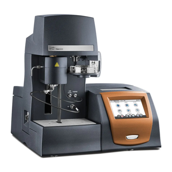
- Page 1 DiScovery TGA TheRmogRAvImeTRIc AnAlyzeR Getting Started Guide for Models 55/550/5500 Revision C Issued February 2018...
- Page 2 TA Instruments may have patents, patent applications, trademarks, copyrights, or other intellectual prop- erty covering subject matter in this document. Except as expressly provided in written license agreement from TA Instruments, the furnishing of this document does not give you any license to these patents, trademarks, copyrights, or other intellectual property.
-
Page 3: Introduction
Introduction Important: TA Instruments Manual Supplement Please click the TA Manual Supplement link to access the following important information supplemental to this Getting Started Guide: • TA Instruments Trademarks • TA Instruments Patents • Other Trademarks • TA Instruments End-User License Agreement •... -
Page 4: Notes, Cautions, And Warnings
Notes, Cautions, and Warnings This manual uses NOTES, CAUTIONS, and WARNINGS to emphasize important and critical instructions. In the body of the manual these may be found in the shaded box on the outside of the page. NOTE: A NOTE highlights important information about equipment or procedures. CAUTION: A CAUTION emphasizes a procedure that may damage equipment or cause loss of data if not followed correctly. -
Page 5: Electromagnetic Compatibility Standards
For United States UL61010-1:2012 Electrical Equipment for Laboratory Use; Part 1: General Requirements. UL61010-2-010:2015 Particular requirements for laboratory equipment for the heating of materials. UL 61010-2-081:2015 Particular requirements for automatic and semi-automatic laboratory equipment for analysis and other purposes. Electromagnetic Compatibility Standards For Australia and New Zealand AS/NZS CISPR11:2015 Limits and methods of measurement of electronic disturbance characteristics of industrial, scientific and medical (ISM) radio frequency equipment. -
Page 6: Safety
If you are not trained in electrical procedures, do not remove the cabinet covers unless specifically instructed to do so in the manual. Maintenance and repair of internal parts must be performed only by TA Instruments or other qualified service personnel. -
Page 7: Electrical Safety
120/240 VAC are present in the instrument. DANGER: Risk of electric shock. High voltages are present in this instrument. Maintenance and repair of internal parts must be performed only by TA Instruments or other qualified service per- sonnel. DANGER: Risque de choc électrique. Présence de tensions élevées dans cet instrument. La maintenance et la réparation des pièces internes doivent être effectuées uniquement par TA... -
Page 8: Mechanical Safety
Mechanical Safety WARNING: Keep your fingers and all other objects out of the path of the furnace when it is mov- ing. The seal is very tight. AVERTISSEMENT: Écartez vos doigts et tous les autres objets du chemin du four lorsqu'il est en mouvement. -
Page 9: Table Of Contents
Important: TA Instruments Manual Supplement ........ - Page 10 Connecting the Discovery TGA to the Controller ........31 Setting Up System Communication .
- Page 11 Replacing Fuses ..............65 Maintaining the Heat Exchanger .
-
Page 12: Chapter 1: Introducing The Discovery Tga
Introducing the Discovery TGA Overview Your TA Instruments Discovery Thermogravimetric Analyzer (Discovery TGA) is used in conjunction with a controller computer and associated software to make up a thermal analysis system. The Discovery TGA measures the amount and rate of weight change in a material, either as a function of increasing temperature or isothermally as a function of time, in a controlled atmosphere. -
Page 13: Tga System Components
TGA System Components The Discovery TGA is comprised of the following major hardware components: • The Tru-Mass™ balance, which provides precise measurement of sample weight. The balance is the key to the TGA system. • The heating system, or furnace (wire-wound for TGA 55 and TGA 550, infrared for TGA 5500), which controls the sample temperature. -
Page 14: Wire-Wound Furnace For Tga 55 And Tga 550
Wire-Wound Furnace for TGA 55 and TGA 550 The wire-wound furnace comes installed on the Discovery TGA 55 and TGA 550. The wire-wound and EGA furnaces can be exchanged as directed in the Online Help. The wire-wound furnace is a resistance heater wound on alumina ceramic, which allows sample zone temperatures as high as 1,000°C with heat- ing rates up to 100°C/min. -
Page 15: Ega Furnace For Tga 55 And Tga 550
EGA Furnace for TGA 55 and TGA 550 The Evolved Gas Analysis (EGA) furnace is an optional accessory for the Discovery TGA 55 and TGA 550 that allows you to connect a spectrometer to the instrument so that the gases evolved by sample decomposition can be analyzed. -
Page 16: Infrared (Ir) Furnace For Tga 5500
Infrared (IR) Furnace for TGA 5500 The IR furnace (shown below) uses quartz halogen lamps as the heat source. Four lamps are arranged in a circular pattern surrounding the quartz tube that encloses the sample area. Infrared energy from the lamps is directed toward the sample area by a water-cooled, gold-plated reflector consisting of four elliptical surfaces. -
Page 17: Discovery Tga Autoloader Or Autosampler
Discovery TGA Autoloader or Autosampler Autoloader The TGA 55 and TGA 550 come standard with an Autoloader (shown below) that automatically loads the pan at the touch of a button or at the start of the run. On the TGA 550 the Autoloader can be upgraded to the Autosampler. -
Page 18: Hi-Res™ Tga
TRIOS Online Help. Hi-Res™ TGA ™ The TA Instruments Hi-Res TGA technique differs from alternative control techniques in that the heating rate of the sample material is dynamically and continuously modified in response to changes in the rate of decomposition of the sample so as to optimize both weight change resolution and time of analysis. -
Page 19: Modulated Tga™ (Mtga™)
Modulated TGA™ (MTGA™) TA Instruments Modulated TGA (MTGA) is an innovative option that is used with Thermogravimetric Analyzers. This option is used to study the same decomposition or volatilization properties as conventional TGA. However, MTGA provides unique capabilities that increase the amount of information obtained from a single TGA experiment, thereby improving the quality of interpretation. -
Page 20: The Discovery Tga User Interface
The Discovery TGA User Interface The Discovery TGA includes an integrated user interface display for local operator control. The functions of the user interface change depending upon the view displayed. This section briefly describes the basic layout of these functions. Status line View panel Primary function buttons... -
Page 21: Primary Function Buttons
Primary Function Buttons Use the following buttons for the main functions of the instrument. Table 1: Primary Function Buttons on the User Interface Key Name Description Start Begins the currently-programmed experiment. This is the same function as Start on the instrument control software. Start automatically loads the selected sample pan and closes the furnace, if necessary, before beginning the experiment. -
Page 22: View Panel
View Panel The view panel provides real-time instrument status and additional functionality pertinent to the selected operation. A list of available functions is described below. Table 2: View Panel Functions on the User Interface Button Name Description System Info Displays instrument information such as the serial number, IP configu- ration, and network configuration. -
Page 23: Additional Function Buttons
Additional Function Buttons Button Name Description Help The Help button can be found on the lower right side of some screens, and displays information regarding use of the currently displayed touch- screen. Motion Stop Displayed while the Autosampler or furnace is in motion. Pressing this button will stop the motion. -
Page 24: Instrument Specifications
Instrument Specifications The tables found below contain the technical specifications for the Discovery TGA 55, TGA 550, and TGA 5500 units and sampling system. Discovery TGA Instrument Characteristics Table 3: Discovery TGA Technical Specifications Item/Area Specifications Dimensions Depth: 56 cm (22 in) Width: 56 cm (22 in) Height: 61 cm (24 in) Weight of instrument... -
Page 25: Discovery Tga Sampling System
WARNING: Do not use corrosive gases, hydrogen, or any other explosive gas in the TGA fur- nace. AVERTISSEMENT: N'utilisez pas de gaz corrosifs, d'hydrogène ou tout autre gaz explosif dans le four TGA. WARNING: Oxygen can be used as a purge gas in the TGA. However, if you use oxygen as a purge gas, you must make sure the furnace is cleaned of hydrocarbons that could combust. -
Page 26: Chapter 2: Installing The Discovery Tga System
13 Closing up the balance and conditioning the balance 14 Filling the heat exchanger reservoir and purging the heat exchanger system of air It is recommended that you have your TGA installed by a TA Instruments Service Representative; call for an installation appointment when you receive your instrument. -
Page 27: Inspecting The System
• If the instrument is damaged, notify the carrier and TA Instruments immediately. • If the instrument is intact but parts are missing, contact TA Instruments. -
Page 28: Preparing The Discovery Tga For Installation
NOTE: Allow free air to circulate around both enclosures. Do not place equipment against walls or cabinets that might impede air flow. Leave at least 7.5 cm (3 in) clearance around the Discovery TGA. WARNING: For safety, position the equipment in a manner that allows access to the power cord for emergency disconnection. -
Page 29: Unpacking The Balance
Unpacking the Balance After removing the bracket, you can proceed to unpack the balance. This very important procedure must be completed before you can use the Discovery TGA. Carefully remove the balance housing cover by loosening the screws. Figure 10 Removing the balance housing cover. Loosen the thumbscrews and remove the balance cover shown in the figure below. - Page 30 Using tweezers, compress the foam and rotate it 90 degrees to eliminate contact with the beam. Gently remove the foam inserts from the sample and tare sides, being careful not to touch the balance. Refer to the figure below. Carefully remove this foam Figure 12 Removing the foam inserts.
-
Page 31: Connecting The Discovery Tga To The Controller
Provides communication between controller and TGA instrument. USB 2.0 Port Provides communications with external accessories. Micro USB 2.0 Port Provides communications for external accessories. SD memory card slot For TA Instruments Service use only. Discovery TGA™ Getting Started Guide Page 31... - Page 32 Table 6: Discovery TGA Back Panel Port Function Audio Jack External speaker communication EVENT Capable of providing a general purpose relay contact closure. 24 VDC OUT Enables control of heat exchanger. WARNING: If connecting oxygen, it should ONLY be connected to the GAS 2 and REACTIVE GAS ports.
-
Page 33: Setting Up System Communication
Setting Up System Communication In order to connect the instrument to a network, you will need to connect the controller computer to a router, then connect the computer to a LAN. Refer to the TRIOS Software Installation Instructions for more details. Connecting Lines to the Gas Delivery Module DANGER: The gas delivery module (GDM) o-rings (on the interior of the GDM) are sealed using ®... - Page 34 Connect the primary gas line to the GAS 1 port. If desired, connect a secondary gas to the GAS 2 port. Refer to Figure 14 for reference. WARNING: If connecting oxygen, it should ONLY be connected to the GAS 2 port. AVERTISSEMENT: Tout raccordement de l'oxygène doit s'effectuer UNIQUEMENT sur l'orifice à...
-
Page 35: Connecting The Air Cool Line
Connecting the Air Cool Line Use the following steps to install the Cooling Gas line: Locate the COOLING GAS fitting on the back panel of the Discovery TGA, marked with a 140 kPa gauge (20 psig) warning label. Make sure your compressed air is regulated between 138 to 172 kPa gauge (20 psig) and is free of water and vapors. -
Page 36: Connecting The Heat Exchanger Cable And Water Hoses
Connecting the Heat Exchanger Cable and Water Hoses Follow these instructions to connect the heat exchanger cable and water hoses: Locate the 24 VDC output connector on the rear of the TGA instrument and connect the heat exchanger cable to the connector. The heat exchanger cable is the only cable that fits into this connector. Remove the water hoses from the packaging. -
Page 37: Connecting The Power Cable
Connecting the Power Cable NOTE: A <HAR>-marked (harmonized) power cable with an IEC 60320 C19 style connector meeting the standards of the country of installation is required for the European Economic Area. Install the power cable as follows: Make sure the power switch is in the Off (0) position, as shown in Figure Plug the power cable into the power entry module (shown below). -
Page 38: Installing The Hang-Down Wires
Installing the Hang-Down Wires The procedures below describe how to install the tare and sample hang-down wires. The following proce- dures assume that the instructions found in “Preparing the Discovery TGA for Installation” on page 28 have been completed. CAUTION: During installation, take care not to bend the hang-down wires or damage the hang- down loops. - Page 39 Figure 18 Inserting tare hang-down wire into installation tool. Insert the wire and installation tool vertically into the tare tube, being careful not to bend the wire. Tare tube Tare hang-down wire with double bend hook at top Tare installation tool Figure 19 Inserting hang-down wire into tare tube.
-
Page 40: Installing The Upper Reflective Assembly And Sample Hang-Down Wire On The Tga 5500
10 Use the alignment gauge (shown below) to ensure that the length of the tare tube extends 0.381-cm (0.150-inch) below the cooling plate. Push it up or pull it down to adjust the length. Place against bottom surface of copper cooling plate Aligns with bottom of tare tube (TGA 550 and 5500) Aligns with bottom of baffles (TGA 5500) / tube ceramic (TGA 55 and TGA 550) - Page 41 up inside the sample side hole in the cooling plate, being sure not to bend the baffles. Be careful not to bend these baffles Figure 22 Installing the upper reflective assembly. With the upper reflective assembly in place, carefully install the DTA thermocouple. Sample hang-down wire Thermocouple Figure 23 Thermocouple installed.
- Page 42 are found in the accessory kit. For now, leave the sample hang-down wire in its case. Figure 24 Sample hang-down wire installation tool. Position the hang-down wire case so that the wire’s double bend hook is at the top. 10 With the sample hang-down wire still in its case, insert the bottom of the wire into the sample hang- down installation tool, as shown below.
- Page 43 12 Carefully angling the sample hang-down installation tool, lower the bottom into the furnace opening until you have enough clearance to hold the tool and wire vertically without bending the wire (very important). Sample hang-down wire Thermocouple Figure 26 Sample hang-down wire. 13 Insert the wire and sample hang-down installation tool vertically into the sample tube, being careful not to bend the wire.
-
Page 44: Installing The Sample Hang-Down Wire On The Tga 55 And Tga 550
17 Slide the installation tool down to remove it from the upper reflective assembly. The hang-down wire, if properly installed through the loop, will remain in position. Be careful not to bend the hang-down wire. 18 Adjust the length of the upper reflective assembly by pulling it down. The length from the bottom of the baffle to the cooling plate should be 1.6 in (4.1 cm), which can be determined using the supplied gauge. -
Page 45: Leveling The Discovery Tga And Aligning The Balance
Leveling the Discovery TGA and Aligning the Balance To avoid weight signal noise, the TGA instrument must be level so that the sample pan and hang-down wire hang inside the furnace without touching the sides. The angle at which the pan hangs is very sensitive to slight irregularities in benchtop surfaces, so it is required that the instrument is installed on a marble bench. - Page 46 NOTE: The position of the hangdown and tare wires was set at the factory. If the instrument is level, no adjustment is necessary. If you need to adjust the balance towards the front or back side, loosen the four horizontal set screws, realign, and then retighten the set screws. Figure 31 Balance alignment locking screws (3 shown).
-
Page 47: Aligning The Bottom Of The Sample Hang-Down Wire
Raise the furnace slowly again to ensure the sample tube baffles clear the furnace. If the baffles come in contact with the furnace, call TA Instruments for service. Lower the furnace, then manually remove the pan and place it back on the Autosampler tray. -
Page 48: Installing The Lower Furnace Assembly On The Tga 5500
Installing the Lower Furnace Assembly on the TGA 5500 After the hang-down wires have been properly aligned, follow these steps to install the lower furnace assembly. Close the furnace completely. Turn off the instrument. Locate the lower furnace assembly in the accessory kit. Carefully remove the lower furnace assembly from the plastic shipping tube. - Page 49 Loosen the outer nut and remove the furnace exhaust tube from the left-hand side of the furnace. Exhaust tube removed from outlet port Figure 36 Outlet port. Look into the furnace outlet port (Figure 37 A). The holes in the heat-absorbing tube (Figure 37 should align with the inlet and outlet ports on the furnace housing, allowing for light to pass through (Figure...
- Page 50 10 Fully tighten the thumbscrew once proper alignment is achieved. 11 Re-install the furnace exhaust tube. 12 Turn off the instrument. Insert the lower furnace assembly cable connector into the connector shown below. Tighten the knurled nut. Lower furnace assembly cable Figure 39 Lower furnace accessory cable installed.
-
Page 51: Closing The Balance Assembly
Closing the Balance Assembly After you have finished the procedures on the previous pages, lower the balance cover carefully over the balance assembly and tighten the two screws as shown in “Unpacking the Balance” on page 29. Then place the Autosampler cover over the tray. The installation procedure is now complete. -
Page 52: Purging Air From The Heat Exchanger System
Continue repeating this procedure until you are satisfied with the clarity of the water in the reservoir after it has circulated. Dispose of the water. Add TA Instruments TGA Conditioner (P/N 952377.901) into the water reservoir. Refer to the instructions on the conditioner bottle for the amount of conditioner to add to the reservoir, then fill the reservoir to the inner rim with distilled water. -
Page 53: Installing The Autosampler Tray
Installing the Autosampler Tray When you receive your TGA, the Autosampler tray is shipped in the accessory box, separate from the instrument. After unpacking the instrument and installing the instrument completely (see instructions in this chapter), you will be ready to run samples using the Autosampler. Locate the open slot on the Autosampler tray. -
Page 54: Starting The Discovery Tga System
Grasp the tray by the center knob and lower it onto the instrument Autosampler, aligning the open slot on the tray with the guide pin on the Autosampler. Guide pin in Autosampler tray open slot Figure 44 Autosampler tray installed on instrument. Starting the Discovery TGA System The power switch is located at the back panel of the instrument. -
Page 55: Shutting Down The Discovery Tga
Shutting Down the Discovery TGA Before you decide to power down your system, consider the following: • All of the components of your thermal analysis system are designed to be powered on for long periods. • The electronics of the TGA perform more reliably if power fluctuations caused by turning units on and off are minimized. -
Page 56: Chapter 3: Use, Maintenance, & Diagnostics
Chapter 3: Use, Maintenance, & Diagnostics Using the Discovery TGA All of your TGA experiments will have the following general outline. In some cases, not all of these steps will be performed. The majority of these steps are performed using the instrument control software. The instructions needed to perform these actions can be found in the online help in the instrument control program;... -
Page 57: Calibrating The Discovery Tga
Calibrating the Discovery TGA To obtain accurate experimental results, you should calibrate the instrument upon initial installation. For the best results, however, you should recalibrate periodically. Several types of calibration are required for the TGA: Autosampler or Autoloader, weight, and temperature calibration. -
Page 58: Temperature Calibration
Temperature Calibration Temperature calibration is required for TGA experiments in which precise transition temperatures are essential. There is one technique for TGA temperature calibration recognized by the American Society for Testing and Materials. This technique is described in ASTM Standard E1582 and is based on the Curie Point of magnetic metals;... -
Page 59: Running A Discovery Tga Experiment
Running a Discovery TGA Experiment All of your TGA experiments will have the following general outline. In some cases, not all of these steps will be performed. See TRIOS software Online Help for anything not covered in this manual. Attaching and setting up external accessories and/or environmental conditions as required, such as the purge gas Selecting the pan size and material Taring the empty sample pan... -
Page 60: Loading The Sample Pans
Loading the Sample Pans Loading Open Pans After taring the sample pan, load the sample as follows: NOTE: This procedure does not apply to sealed aluminum pans. If you are using sealed pan, a different procedure applies. See below. Place the sample in the sample pan and position the pan on the sample tray in its original position; this may be done with the tray on or off the instrument. -
Page 61: Starting An Experiment
Reposition the bail/pan on the sample tray in its original pan position; this may be done with the tray on or off the instrument. The tab on the bail should align with the groove in the tray so that the sample pan can be picked up by the sample hang-down wire. -
Page 62: Furnace Installation
Lay the furnace assembly down on the left side of the instrument so that the hose connections are posi- tioned over the drip pan. Then carefully snip the wire ties and disconnect the cooling water lines from the housing. (A small amount of cooling water will drain out into the pan when the hoses are disconnected.) The furnace is now completely free from the instrument. -
Page 63: Maintaining The Instrument
Maintaining the Instrument The primary maintenance procedures described in this section are the customer’s responsibility. Any fur- ther maintenance should be performed by a representative of TA Instruments or other qualified service per- sonnel. Consult TRIOS software Online Help for further information. -
Page 64: Cleaning The Pans
Cleaning the Pans The TGA platinum and ceramic sample pans are designed to be reusable. However, they must be thor- oughly cleaned between experiments. This is typically accomplished by “burn-off” of residue with a pro- pane torch. In some cases, soaking the pans in an appropriate solvent provides another alternative. Care must be taken not to deform the pan and bail wire during cleaning, or the TGA automatic pan pick-up process will not work. - Page 65 Add distilled water to the reservoir, when necessary, to keep the reservoir at least 2/3 full. If algae growth is visible, drain the reservoir, refill it with distilled water, and add TA Instruments TGA Condi- tioner (PN 952377.901), as described in the Maintaining the Heat Exchanger TRIOS Online help topic.
- Page 66 Fuse 12-amp time delay, 250 V (T12 A H 250 V) 251470.010 Ethernet cable (10 foot, shielded) 920223.901 Event cable *Contact your local TA Instruments representative for information on non-US style power cords. Table 8: Discovery TGA Tools and Parts Part Number Description 259508.000...
- Page 67 Requires 25-pan tray, P/N 957099.901. Requires several additional parts found in Sealed Aluminum Pan Kit, P/N 957352.901. Not available for TGA 55. Requires TA Instruments blue sample press, P/N 900878.902, or Tzero sample press, P/N 901900.901, with purple die set, P/N 957450.901.
- Page 68 Table 10: Calibration/Reference Materials Part Number Description 957349.901 Mass Spectrometer Interface Kit for the IR furnace (TGA 5500 only) 271001.002 Mass Spectrometer Interface Kit for the EGA furnace (TGA 55 and TGA 550) 200413.002 Calibration weight 100 mg - Class 1 200413.001 Calibration weight 50 mg - Class 1 900905.901...
Need help?
Do you have a question about the TGA5500 and is the answer not in the manual?
Questions and answers