
Related Manuals for TA Instruments TGA 2050


Summary of Contents for TA Instruments TGA 2050
- Page 1 TGA 2050 Thermogravimetric Analyzer Operator’s Manual PN 925603.001 Rev. D (Text and Binder) PN 925603.002 Rev. D (Text Only) Issued July 2000 TA I TGA 2050 NSTRUMENTS...
- Page 2 TA I TGA 2050 NSTRUMENTS...
- Page 3 Table of Contents TA I TGA 2050 NSTRUMENTS...
- Page 4 Table of Contents TA I TGA 2050 NSTRUMENTS...
- Page 5 Table of Contents TA I TGA 2050 NSTRUMENTS...
- Page 6 Table of Contents TA I TGA 2050 NSTRUMENTS...
- Page 7 Table of Contents TA I TGA 2050 NSTRUMENTS...
- Page 8 A CAUTION emphasizes a procedure that may CAUTION: damage equipment or cause loss of data if not followed correctly. A WARNING indicates a procedure that WARNING may be hazardous to the operator or to the environment if not followed correctly. TA I TGA 2050 VIII NSTRUMENTS...
- Page 9 Hotlines To TA Instruments Thermal Analysis TA I TGA 2050 NSTRUMENTS...
- Page 10 Chemical Safety Do not use hydrogen or any other explosive WARNING gas in the TGA 2050 furnace. If you are using samples that may emit WARNING harmful gases, vent the gases by placing the instrument near an exhaust.
- Page 11 This is particularly important if oxygen is used as a purge gas in the TGA 2050. See Chapter 5 for instructions. The TGA 2050 furnace assembly also WARNING contains refractory ceramic fiber (RCF) insulation. This insulation is enclosed within the furnace housing.
- Page 12 Using This Manual TA I TGA 2050 NSTRUMENTS...
-
Page 13: Table Of Contents
CHAPTER 1: Introducing the TGA 2050 Introduction..........1-3 Components ..........1-4 The 2050 Instrument ........ 1-6 Automatic Keypad Functions .... 1-9 Front Panel lights ......1-9 Accessories ........... 1-10 Gas Switching Accessory ....1-10 Other Accessories ......1-10 Specifications ........1-11... - Page 14 Introducing the TGA 2050 1–2 TA I TGA 2050 NSTRUMENTS...
-
Page 15: Introduction
TA Instruments PC-based controllers. The TGA 2050 measures the amount and rate of weight change in a material, either as a function of increasing temperature, or isothermally as a function of time, in a controlled atmosphere. -
Page 16: Components
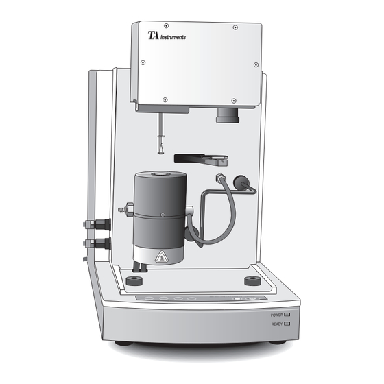
Thermogravimetric Analyzer (TGA) 2050 with PC-Based TA Instruments Thermal Analyzer Components The TGA 2050 has five major components, illustrated in Figure 1.2: • The balance, which provides precise measurement of sample weight. The balance is the key to the TGA system. - Page 17 Introduction Balance Cabinet Furnace Heat Exchanger Sample Loading Assembly Figure 1.2 TGA 2050 Components TA I TGA 2050 1–5 NSTRUMENTS...
-
Page 18: The 2050 Instrument
Introducing the TGA 2050 The 2050 Instrument The instrument keypad (Figure 1.3) contains keys that control local operations at the instru- ment (automatic balance tare, furnace elevator, sample loading platform, and experiment start and stop functions). Stop Start Figure 1.3 TGA 2050 Keypad Table 1.1 explains the functions of the instru-... - Page 19 This key can be pressed while the furnace is moving to reverse the direction of movement. START Begins the experiment. This is the same function as Start on the controller. (table continued) TA I TGA 2050 1–7 NSTRUMENTS...
- Page 20 Introducing the TGA 2050 Table 1.1 Instrument Keypad Function Keys (continued) Key/Function Explanation STOP If an experiment is running, this key ends the method normally, as though it had run to completion; i.e., the method-end conditions go into effect, and the data that has been generated is saved.
-
Page 21: Automatic Keypad Functions
START can be pressed while a sample • load is in progress. Front Panel Lights The front panel green power light shows that the instrument is on; the yellow light shows that the instrument is ready. TA I TGA 2050 1–9 NSTRUMENTS... -
Page 22: Accessories
Introducing the TGA 2050 Accessories Gas Switching Accessory The TA Instruments Gas Switching Accessory can be used to turn the purge gas on and off or to switch between two different purge gases during TGA experiments. Other Accessories The TGA can be used with many standard... -
Page 23: Specifications
Specifications Specifications Table 1.2 TGA 2050 Specifications Temperature range C to 1000 Thermocouple Platinel II* Heating rate 0.1 to 50°C/min Operating line voltage 115 volts, 50/60 Hz Energy consumption 1.5 kVA *Platinel II is a registered trademark of Engelhard Industries. - Page 24 Introducing the TGA 2050 Table 1.3 Sampling System Sample pans Types Platinum, Alumina ), Aluminum Volume capacity Platinum: 50 µL, 100 µL Alumina: 100 µL, 250 µL, 500 µL Aluminum: 100 µL Weighing capacity 1.0 gm Balance measurement Resolution 0.2 µg Accuracy <...
- Page 25 Specifications Do not use hydrogen or WARNING any other explosive gas in the TGA 2050. Oxy- gen may be used. How- ever, the furnace must be kept clean of hydrocar- bons to prevent combus- tion. TA I TGA 2050 1–13...
- Page 26 Introducing the TGA 2050 1–14 TA I TGA 2050 NSTRUMENTS...
- Page 27 CHAPTER 2: Installing the TGA 2050 Unpacking/Repacking the 2050 ....2-3 Unpacking the 2050 ......2-3 Repacking the 2050 ......2-6 Installing the Instrument ......2-7 Inspecting the System......2-8 Choosing a Location ......2-9 Filling the Heat Exchanger....2-10 Connecting Cables and Lines ....
- Page 28 Installing the TGA 2050 Starting the 2050 ........2-32 Shutting Down the Instrument ....2-33 2–2 TA I TGA 2050 NSTRUMENTS...
-
Page 29: Unpacking/Repacking The 2050
Unpacking/Repacking the 2050 Unpacking/Repacking the 2050 Due to the delicate mechanisms contained in the NOTE: TGA 2050 balance, the balance will be unpacked later, see page 2-21. Refer to Figures 2.1 to 2.3 while unpacking your instrument. Unpacking the 2050... - Page 30 Installing the TGA 2050 1. Open the shipping carton and remove the accessory box. 2. Remove the cardboard packing insert. 3. Stand at one end of the box with your assistant facing you at the other end. Lift your end of the unit out of the box as your assistant lifts his/her end.
- Page 31 9. Turn the instrument to face front and use a wrench to remove the furnace clamp from the unit. Retain this clamp in case the instrument needs to be shipped in the future. TA I TGA 2050 2–5 NSTRUMENTS...
-
Page 32: Repacking The 2050
Installing the TGA 2050 Figure 2.3 Installing the Mounting Feet 10. Follow the directions beginning on page 2-7 to install the instrument before you unpack the balance. Repacking the 2050 To pack and ship your instrument, use the hardware retained during unpacking and reverse the instructions found on pages 2-3 to 2-5. -
Page 33: Installing The Instrument
Installing the Instrument Installing the Instrument Before shipment, the TGA 2050 instrument is inspected both electrically and mechanically so that it is ready for operation upon proper instal- lation. Installation involves the following procedures, described in this chapter: • Unpacking the instrument and its components and accessory kit •... -
Page 34: Inspecting The System
If the instrument is damaged, notify the carrier and TA Instruments immediately. If the instrument is intact but parts are missing, contact TA Instruments. A list of TA Instruments phone numbers can be found in Appendix A of this manual. 2–8 TA I... -
Page 35: Choosing A Location
60 Hz, 15 amps). A step up/down line transformer may be required if the unit is operated at a higher or lower line voltage..your TA Instruments thermal analysis controller..compressed lab air and purge gas supplies with suitable regulators and flow meters. -
Page 36: Filling The Heat Exchanger
Installing the TGA 2050 Drying out the instrument may be needed, if it has NOTE: been exposed to humid conditions. It is important to be certain that the instrument ground is adequately connected to the facilities ground for safe operation. - Page 37 Fill to bottle's inner rim Figure 2.5 Heat Exchanger Bottle 2. Pour one half bottle of TA Instruments TGA Conditioner (PN 952377.001) into the water reservoir bottle. Then fill the bottle to the inner rim (see Figure 2.5) with distilled water.
-
Page 38: Connecting Cables And Lines
Installing the TGA 2050 Connecting Cables and Lines To connect the cables and water and gas lines, you will need access to the TGA instrument’s rear panel. All directional descriptions are written on the assumption that you are facing the back of the instrument. - Page 39 7. Connect the other end of the unmarked water line to the connector labeled “RE- TURN” on the heat exchanger. Figure 2.7 on the next page illustrates the correct water line connections for the TGA and heat exchanger. TA I TGA 2050 2–13 NSTRUMENTS...
-
Page 40: Gpib Cable
Installing the TGA 2050 Figure 2.7 Heat Exchanger Water Line Connections NOTE: Air trapped in the heat exchanger system must be purged before starting the first run. After installa- tion of the TGA is complete, turn on the instru- ment by placing the HEATER and POWER switches in the ON position. - Page 41 Installing the Instrument 4. Connect the other end of the GPIB cable to the controller or to the GPIB cable of another TA Instruments instrument con- nected to the controller. 5. Select an address from 1 to 9. Then use the...
- Page 42 Installing the TGA 2050 Table 2.1 Binary Address Settings Switch Pattern Address 1 2 3 4 5 0 0 0 0 1 0 0 0 1 0 0 0 0 1 1 0 0 1 0 0 0 0 1 0 1...
-
Page 43: Purge Lines
Purge Lines Do not use any liquid in the purge lines. WARNING 1. Locate the PURGE and BALANCE PURGE fittings on the back of the TGA instrument (Figure 2.9). Figure 2.9 TGA PURGE Fittings TA I TGA 2050 2–17 NSTRUMENTS... - Page 44 If you are using laboratory purge, rather than NOTE: bottled purge, you will need to install an external drier. The use of corrosive gases in the TGA 2050 are CAUTION: not recommended. Use of an explosive gas as a purge gas is...
-
Page 45: Cooling Gas Line
25 and 120 psig and is free of oil and water vapors. 3. Connect a compressed lab air line to the COOLING GAS fitting. Nitrogen may also be used as a cooling gas. NOTE: TA I TGA 2050 2–19 NSTRUMENTS... -
Page 46: Power Cable
Installing the TGA 2050 Power Cable 1. Make sure the TGA POWER switch, located on the back of the instrument, (Figure 2.11) is in the OFF position. Power Switch 10 A Figure 2.11 TGA POWER Switch 2. Plug the power cable into the TGA. -
Page 47: Unpacking The Balance
Unpacking the Balance Unpacking the Balance When unpacking the balance, be careful not to CAUTION: damage the balance arm or hang-down loops. Tare Sample Side Side Balance Cover Balance Cover Screw Tare Hang-Down Tube Loop TA I TGA 2050 2–21 NSTRUMENTS... - Page 48 Installing the TGA 2050 Foam Insert 2–22 TA I TGA 2050 NSTRUMENTS...
-
Page 49: Installing The Hang-Down Wires
Installing the Hang-Down Wires Installing the Hang-Down Wires During installation, take care not to bend the CAUTION: hang-down wires or damage the hang-down loops. FURNACE TA I TGA 2050 2–23 NSTRUMENTS... - Page 50 Installing the TGA 2050 Hang-Down Tube To make the hang-down loops easier to see, we NOTE: suggest sliding a piece of white paper into the balance chamber behind each loop before you hook the hang-down wire into it. (Do not forget to remove the paper when finished.)
- Page 51 Installing the Hang-Down Wires TA I TGA 2050 2–25 NSTRUMENTS...
- Page 52 Installing the TGA 2050 2–26 TA I TGA 2050 NSTRUMENTS...
-
Page 53: Aligning The Sample Hang-Down Wire
Installing the Hang-Down Wires Aligning the Sample Hang-Down Wire LOAD TA I TGA 2050 2–27 NSTRUMENTS... - Page 54 Installing the TGA 2050 Balance Adjustment Screw Hang-Down Loop and Wire Top of Hang-Down Tube 2–28 TA I TGA 2050 NSTRUMENTS...
- Page 55 Installing the Hang-Down Wires FURNACE STOP TA I TGA 2050 2–29 NSTRUMENTS...
- Page 56 Installing the TGA 2050 Hang-Down Tube Sample Furnace Housing FURNACE UNLOAD 2–30 TA I TGA 2050 NSTRUMENTS...
-
Page 57: Adjusting The Sample Platform
Installing the Hang-Down Wires Adjusting the Sample Platform TA I TGA 2050 2–31 NSTRUMENTS... - Page 58 Installing the TGA 2050 Starting the TGA 2050 Allow the TGA to warm up for at least 30 minutes NOTE: before performing an experiment. 2–32 TA I TGA 2050 NSTRUMENTS...
- Page 59 Shutting Down the Instrument Shutting Down the Instrument TA I TGA 2050 2–33 NSTRUMENTS...
- Page 60 Installing the TGA 2050 2–34 TA I TGA 2050 NSTRUMENTS...
- Page 61 CHAPTER 3: Running Experiments TA I TGA 2050 3–1 NSTRUMENTS...
- Page 62 Running Experiments 3–2 TA I TGA 2050 NSTRUMENTS...
- Page 63 Overview Overview TA I TGA 2050 3–3 NSTRUMENTS...
- Page 64 Running Experiments Before You Begin 3–4 TA I TGA 2050 NSTRUMENTS...
- Page 65 Calibrating the TGA Calibrating the TGA Temperature Calibration TA I TGA 2050 3–5 NSTRUMENTS...
- Page 66 Running Experiments Weight Calibration Running a TGA Experiment Experimental Procedure 3–6 TA I TGA 2050 NSTRUMENTS...
- Page 67 Running an Experiment Preparing the Sample Selecting Sample and Tare Pans TA I TGA 2050 3–7 NSTRUMENTS...
- Page 68 Running Experiments NOTE: Whenever a different type of pan is selected, the balance must be mechanically tared using step 1 of the weight calibration. Taring the Sample Pan 3–8 TA I TGA 2050 NSTRUMENTS...
- Page 69 Running an Experiment Automatic Tare TARE Manual Tare LOAD FURNACE UNLOAD TA I TGA 2050 3–9 NSTRUMENTS...
- Page 70 Running Experiments Loading the Sample NOTE: Always use brass tweezers to handle the sample pans. Manually loading the sample pan onto the hang- CAUTION: down wire may damage the balance mechanism. 3–10 TA I TGA 2050 NSTRUMENTS...
- Page 71 Running an Experiment LOAD NOTE: The position of the thermocouple should be the same as it was during temperature calibration. Thermocouple Sample Hook Thermocouple should be about 2mm from the pan surface. Sample Pan TA I TGA 2050 3–11 NSTRUMENTS...
- Page 72 Running Experiments FURNACE 3–12 TA I TGA 2050 NSTRUMENTS...
- Page 73 Running an Experiment TA I TGA 2050 3–13 NSTRUMENTS...
- Page 74 Running Experiments Setting Up an Experiment 3–14 TA I TGA 2050 NSTRUMENTS...
- Page 75 Running an Experiment Setting Up Accessories Using a Purge Gas TA I TGA 2050 3–15 NSTRUMENTS...
- Page 76 Running Experiments Do not use hydrogen or any other explosive WARNING gas in the TGA 2050 furnace. Oxygen may be used as a purge gas, but the furnace must be kept clean of volatile hyrdrocarbons to prevent combustion. Do not use any liquid in the purge lines.
- Page 77 Running an Experiment TA I TGA 2050 3–17 NSTRUMENTS...
- Page 78 Air Cool can be used with the furnace closed. NOTE: However, if the temperature is above 500°C, the furnace will cool naturally until it is 500°C or less, then Air Cool will begin. Using the Gas Switching Accessory 3–18 TA I TGA 2050 NSTRUMENTS...
- Page 79 Running an Experiment TA I TGA 2050 3–19 NSTRUMENTS...
- Page 80 START NOTE: Once the experiment is started, operations are best performed at the controller keyboard. The TGA 2050 is very sensitive to motion and might pick up the vibration caused by pressing a key on the instrument keypad. Forced Start START 3–20...
- Page 81 NOTE: The Heat Exchanger will continue to run as long as the Air Cool option is activated or until the indi- cated temperature is below 50 The REJECT function discards all experiment CAUTION: data. TA I TGA 2050 3–21 NSTRUMENTS...
- Page 82 Running Experiments Unloading the Sample UNLOAD 3–22 TA I TGA 2050 NSTRUMENTS...
- Page 83 Use in an Oxygen-Free Atmosphere Use in an Oxygen-Free Atmosphere Purge Gas System TA I TGA 2050 3–23 NSTRUMENTS...
- Page 84 Running Experiments Instrument Setup When the TGA is idle, leave the system closed and NOTE: continue purging with the inert gas. 3–24 TA I TGA 2050 NSTRUMENTS...
- Page 85 CHAPTER 4: Technical Reference Description of the TGA 2050 ....4-3 Components .......... 4-5 Balance .......... 4-6 Sample Loading Assembly .... 4-8 Furnace .......... 4-9 Cabinet ......... 4-11 Heat Exchanger ......4-13 Theory of Operation ......... 4-14 Status Codes ..........4-15...
- Page 86 Technical Reference 4–2 TA I TGA 2050 NSTRUMENTS...
-
Page 87: Description Of The Tga 2050
This current is converted to the weight signal. The TGA 2050 has two weight ranges: 1 gm and 100 mg. Both ranges are continuous over their weight loss operating range, which means that the entire weight loss range can be viewed without any loss of information. - Page 88 Heating rate and sample temperature are mea- sured by the thermocouple located above the sample. This enables the controller to program and maintain the sample environment at your selected rate. 4–4 TA I TGA 2050 NSTRUMENTS...
-
Page 89: Components
Description of the TGA 2050 Components The TGA 2050 has five major components, illustrated in Figure 4.1: the balance, the sample loading assembly, the furnace, the cabinet, and the heat exchanger. Balance Chamber Sample Thermocouple Loading Assembly Heat Furnace Exchanger... -
Page 90: Balance
The balance arm is a rhombic piece of alumi- num attached to the meter movement. It is in a null balance system. A hang-down loop is attached to each end to hold the hang-down wires. 4–6 TA I TGA 2050 NSTRUMENTS... - Page 91 Description of the TGA 2050 The balance arm sensor is a printed circuit board assembly that detects the null position of the meter movement. The balance beam sensor is mounted above the balance arm. It is used in conjunction with the analog circuitry to maintain a null position.
-
Page 92: Sample Loading Assembly
It also pivots the platform away from the furnace area for easy sample loading and unloading. Figure 4.3 Sample Loading Assembly 4–8 TA I TGA 2050 NSTRUMENTS... -
Page 93: Furnace
Description of the TGA 2050 Furnace The TGA furnace consists of a quartz glass sample tube surrounded by an electric resistance heater, both of which are contained within a water-cooled furnace housing. The housing is mounted to a furnace base that raises and lowers the furnace for sample loading and unloading. - Page 94 The furnace base moves the furnace assembly up around the sample pan to the closed position, or down away from the sample pan to the open position. Platinel II is a registered trademark of Engelhard Industries. 4–10 TA I TGA 2050 NSTRUMENTS...
-
Page 95: Cabinet
Description of the TGA 2050 Cabinet The TGA cabinet (Figure 4.5) consists of the cabinet housing, the keypad, the electronics compartment, the purge and cooling gas fittings, and the rear panel. Figure 4.5 TGA Cabinet Components The TGA cabinet housing consists of a base and a rear cover. - Page 96 The rear panel (Figure 4.6) has the signal and power connections for the instrument; the fuses; the ready light; the POWER switch; the address switches; the purge, gas, cooling accessory, and GPIB connections; and the Reset button. Figure 4.6 Rear Panel 4–12 TA I TGA 2050 NSTRUMENTS...
-
Page 97: Heat Exchanger
Description of the TGA 2050 Heat Exchanger The heat exchanger (Figure 4.7) consists of a fan, a radiator, a water reservoir, a pump, a temperature switch, and a flow switch. The fan blows cool air through the radiator. The radiator exchanges heat between the water and air. -
Page 98: Theory Of Operation
Two modes are commonly used for investigating thermal stability behavior in controlled atmospheres: (1) dynamic, in which the temperature is increased at a linear rate, and (2) isothermal, in which the tempera- ture is kept constant. 4–14 TA I TGA 2050 NSTRUMENTS... -
Page 99: Status Codes
This may be caused by a large ballistic jump in the program, a faulty heater, or a faulty control thermo- couple signal. Complete The thermal method has finished. (table continued) TA I TGA 2050 4–15 NSTRUMENTS... - Page 100 The temperature is beyond the set point, and the instrument cannot remove heat fast enough to follow the thermal program. This is usually caused by a large ballistic jump to a lower tempera- ture. (table continued) 4–16 TA I TGA 2050 NSTRUMENTS...
- Page 101 Opening The furnace assembly is opening. Ready The system has equili- brated at the initial temperature and is ready to begin the next segment. Use the Start function to continue the method. (table continued) TA I TGA 2050 4–17 NSTRUMENTS...
- Page 102 (see Set Up above), but the initial weight has been measured and data col- lection has begun. The thermal method will start when the normal setup process has been completed. (table continued) 4–18 TA I TGA 2050 NSTRUMENTS...
- Page 103 Temp The heater is in stand-by mode, and the experiment has been terminated. Unload The TGA is unloading a sample from the balance. TA I TGA 2050 4–19 NSTRUMENTS...
- Page 104 Technical Reference 4–20 TA I TGA 2050 NSTRUMENTS...
- Page 105 Exchanger Coolant ......5-7 Draining and Refilling the Water Reservoir ......5-7 Replacing the Thermocouple ....5-10 Diagnosing Power Problems .....5-12 Fuses ...........5-12 Power Failures ........5-13 TGA 2050 Test Functions ......5-14 The Confidence Test ......5-14 Replacement Parts ........5-16 TA I TGA 2050 5–1 NSTRUMENTS...
- Page 106 Maintenance & Diagnostics 5–2 TA I TGA 2050 NSTRUMENTS...
-
Page 107: Overview
Overview The procedures described in this section are the customer’s responsibility. Any further mainte- nance should be performed by a representative of TA Instruments or other qualified service personnel. Because of the high voltages in this instru- WARNING ment, untrained personnel must not at- tempt to test or repair any electrical circuits. -
Page 108: Routine Maintenance
Do not touch the furnace sample tube with WARNING your bare fingers. Skin oils may cause devitrification of the quartz glass, resulting in severely reduced sample tube life. 5–4 TA I TGA 2050 NSTRUMENTS... - Page 109 Do not disturb the hangdown wire and WARNING furnace thermocouple located directly above the furnace when cleaning the fur- nace, as damage may result. FURNACE TA I TGA 2050 5–5 NSTRUMENTS...
- Page 110 7. Replace the rubber cap on the quartz tube stem when you have completed the cleaning procedure. 8. Purge the system with nitrogen for one hour. 9. Heat the furnace to 900°C to remove any remaining solvent. 5–6 TA I TGA 2050 NSTRUMENTS...
-
Page 111: Heat Exchanger
Add distilled water to the reservoir, if necessary, to keep the reservoir at least 2/3 full. If algae growth is visible, drain the reservoir bottle, refill it with distilled water, and add TA Instruments TGA Conditioner, as described in the next section. - Page 112 4. Dispose of the water and fill the bottle with TGA Conditioner (PN 952377.001) and fresh distilled water as directed in Chapter 2 on pages 2-10 and 2-11. 5–8 TA I TGA 2050 NSTRUMENTS...
- Page 113 Cool, and circulate the water until the air bubbles disappear from the water lines. (You may see “Err 119” on the instrument display until all the air has been removed.) 6. Replace and tighten the water reservoir cap. TA I TGA 2050 5–9 NSTRUMENTS...
-
Page 114: Replacing The Thermocouple
(Figure 5.2). Figure 5.2 Removing the Thermocouple 5. Unplug the thermocouple from its connector and remove the thermocouple from the balance chamber. 6. Plug the new thermocouple carefully into the connector. 5–10 TA I TGA 2050 NSTRUMENTS... - Page 115 (Figure 5.3). Figure 5.3 Checking Position of Thermocouple 10. Make sure that the hang-down wire does not touch the top of the thermocouple inside the balance chamber. 11. Replace the balance chamber faceplate and screws. TA I TGA 2050 5–11 NSTRUMENTS...
-
Page 116: Diagnosing Power Problems
TGA’s rear panel. Both are housed in safety-approved fuse carriers, labeled F1 and F2 (Figure 5.4). Always unplug the instrument before you WARNING examine or replace the fuses. 10 A Figure 5.4 Fuse Locations 5–12 TA I TGA 2050 NSTRUMENTS... -
Page 117: Power Failures
115 volts AC (+ 10%), 50 or 60 Hz. It should not be operated outside this range. Low line voltage may result in poor instrument operation; high line voltage may damage the instrument. TA I TGA 2050 5–13 NSTRUMENTS... -
Page 118: Tga 2050 Test Functions
Maintenance & Diagnostics TGA 2050 Test Functions The TGA 2050 has three levels of test and diagnostic functions: • The confidence test that is run every time the instrument is started. • Cycling test functions that continuously test specific. •... - Page 119 The instrument cannot be configured online when fatal errors are detected. Contact your TA Instruments service representative for assistance. If the confidence test detects a non-fatal problem...
-
Page 120: Replacement Parts
Maintenance & Diagnostics Replacement Parts Table 5.1 TGA 2050 Parts List Part Number Description 952018.906 100 µL platinum sample pan kit 952018.907 100 µL ceramic sample pan kit 952040.901 Sample hang-down wire 952040.902 Tare hang-down wire 952011.906 Class M calibration... - Page 121 TGA Temperature Calibration Kit 952183.901 Aluminum temperature calibration standard 900905.901 Calcium oxalate sample 990806.901 Air purge valve assembly 952410.001 TGA 2050 keypad assembly 993008.901 Power supply assembly 990850.901 Central processor PCB 993100.901 Communications PCB 990870.901 Triac drive PCB 259508.000 Brass tweezers 259509.000...
- Page 122 Maintenance & Diagnostics Table 5.1 (continued) Part Number Description 952161.901 Flow switch assembly 269932.001 Solid state relay 952381.901 Upper furnace core kit, 952382.901 Lower furnace core kit, 952357.901 Furance tube replace- ment kit, EGA 5–18 TA I TGA 2050 NSTRUMENTS...
- Page 123 Appendix A: Ordering Information For information or to place an order, contact: United States: TA Instruments, Inc. 109 Lukens Drive New Castle, DE 19720 Telephone: (302) 427-4000 Fax: (302) 427-4001 Overseas: TA Instruments Ltd. Europe House Bilton Centre Cleeve Road...
- Page 124 Appendix A TA Instruments Benelux Ottergemsesteenweg 461 B-9000 Gent Belguim Telephone: 32-9-220-79-89 Fax: 32-9-220-83-21 TA Instruments Japan Iwata Building #5 28-11 Nishigotanda 2-Chome Shinagawa-Ku, Tokyo 141 Japan Telephone: 813-5434-2711 Fax: 813-5434-2770 For technical assistance or service in the United States:...
- Page 125 Index Index TA I TGA 2050 I–1 NSTRUMENTS...
- Page 126 Index FURNACE I–2 TA I TGA 2050 NSTRUMENTS...
- Page 127 Index LOAD TA I TGA 2050 I–3 NSTRUMENTS...
- Page 128 Index STOP TARE START I–4 TA I TGA 2050 NSTRUMENTS...
- Page 129 Index UNLOAD TA I TGA 2050 I–5 NSTRUMENTS...
- Page 130 Index I–6 TA I TGA 2050 NSTRUMENTS...
Need help?
Do you have a question about the TGA 2050 and is the answer not in the manual?
Questions and answers