
Related Manuals for TA Instruments Nano ITC Series


Summary of Contents for TA Instruments Nano ITC Series
- Page 1 Nano Isothermal Titration Calorimeter (Nano ITC) Getting Started Guide for Models 5300, 5301, 5302 Revision F Issued February 2011...
- Page 2 TA Instruments may have patents, patent applications, trademarks, copyrights, or other intellectual prop- erty covering subject matter in this document. Except as expressly provided in written license agreement from TA Instruments, the furnishing of this document does not give you any license to these patents, trade- marks, copyrights, or other intellectual property.
-
Page 3: Introduction
Introduction Important: TA Instruments Manual Supplement Please click the TA Manual Supplement link to access the following important information supplemental to this Getting Started Guide: • TA Instruments Trademarks • TA Instruments Patents • Other Trademarks • TA Instruments End-User License Agreement •... -
Page 4: Notes, Cautions, And Warnings
Notes, Cautions, and Warnings This manual uses NOTES, CAUTIONS, and WARNINGS to emphasize important and critical instructions. In the body of the manual these may be found in the shaded box on the outside of the page. NOTE: A NOTE highlights important information about equipment or procedures. CAUTION: A CAUTION emphasizes a procedure that may damage equipment or cause loss of data if not followed correctly. -
Page 5: Safety
WARNING: If this instrument is used in a manner not intended or specified in this manual, the protection provided by the instrument may be impaired. DANGER: High voltages are present in this instrument. Maintenance and repair of internal parts must be performed only by TA Instruments or other qualified service personnel. Safety High voltages are present in this instrument. - Page 6 This page is intentionally blank. Page 6 Nano ITC Getting Started Guide...
-
Page 7: Table Of Contents
Important: TA Instruments Manual Supplement ........ - Page 8 Chapter 3: Use, Maintenance, & Diagnostics ................23 Overview ..............23 Calibrating Chemicals .
-
Page 9: Chapter 1: Introducing The Nano Itc
Chapter: 1 Introducing the Nano ITC Overview There are three ways in which a calorimeter may be designed. Heat measurements may be based on the following: • A temperature rise measured in a system of known heat capacity, (ΔT) • The measured change in power (typically resistance heating) required to maintain a system at a constant temperature (power compensation), and •... -
Page 10: The Nano Isothermal Titration Calorimeter (Itc)
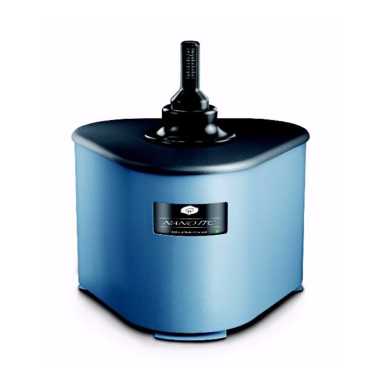
The Nano Isothermal Titration Calorimeter (ITC) The Nano ITC (shown in the figure below) consists of the measuring unit (calorimeter block and two non- removable reaction vessels), the buret assembly, which includes the stirring system, and a cleaning acces- sory. With the exception of the power on/off switch located on the back of the calorimeter unit, all func- tions of the Nano ITC are controlled remotely by the computer through the USB connection. -
Page 11: Titration/Data Analysis
The baseline data, i.e. heat flow in the regions before and after each titrant pulse, shows the power required to maintain a zero temperature difference between the sample and reference cells. The baseline in this region is a function of heating by stirring. The baseline is used to calculate the area or the heat from each pulse in the reaction vessel during the titration or batch reaction. -
Page 12: System Components
System Components • Nano Isothermal Titration Calorimeter • Personal computer (optionally available from TA Instruments) • ITCRun and NanoAnalyze software • Power cord • Getting Started Guide (this manual) • Data Collection and Analysis Software • 1 each 2.5-mL filling syringe with 16-gauge, 8-inch long needle (Standard Volume ITC) •... -
Page 13: Reaction Vessel
CAUTION: The purge port valve on the back of the Nano ITC should remain in the closed posi- tion at all times to maintain the integrity of the nitrogen purge. NOTE: Purging of the canister is not a routine maintenance operation; contact TA Instruments before proceeding. -
Page 14: Syringe/Stirrer
Syringe/Stirrer Nano ITC Standard Volume systems include two syringes of 100 and 250 µL capacities. Two buret syringes are provided with 100 µL and 250 µL capacities. The only difference in dimension between the two is the inner diameter of the syringe barrel; the needles are identical in order to maintain the thermal and mechanical properties. -
Page 15: Buret Assembly
Each syringe needle is equipped with a flattened, twisted paddle at the tip, which does the actual stirring of the solutions in the cell. The stirring paddle spins clear of the sides of the reaction vessel. When stirring is activated, the contents of the reaction vessel are stirred continuously until the end of the experiment or until stirring is turned off. -
Page 16: Instrument Specifications
Instrument Specifications The table found below contains the technical specifications for the Nano ITC instrument. Table 1: Nano ITC Technical Specifications Item/Area Specifications Dimensions Depth 38 cm (15 in.) Width 37 cm (14 in.) Height 32 cm (13 in.) Weight 20 kg (43 lbs) Power 100–240 VAC, 3 amps. -
Page 17: Chapter 2: Installing The Nano Itc
Connecting the Nano ITC to the TA Instruments controller computer • Connecting USB cables It is recommended that you have your Nano ITC installed by a TA Instruments Service Representative; call for an installation appointment when you receive your instrument. Inspecting the System When you receive your instrument, look over the instrument and shipping container carefully for signs of shipping damage, and check the parts received against the enclosed shipping list. -
Page 18: Choosing A Location
• a stable work surface. Near • a power outlet. See the “Power Requirements” section below. • your TA Instruments computer. Away from • dusty environments. • exposure to direct sunlight. • direct air drafts (fans, room air ducts). •... -
Page 19: Setting Up The Nano Itc
Setting Up the Nano ITC When you have received your TA Instruments Nano ITC, follow these basic steps to set it up for use. For detailed information refer to the sections that follow. Unpack and inspect the instrument and all components. -
Page 20: Starting The Nano Itc
Starting the Nano ITC Once you have completely set up the calorimeter and computer system, you can start the instrument as follows: Turn on the surge suppressor power switch and the computer system and monitor. Turn on the power switch to the calorimeter, which is located on the back panel. The front LED will light up green when in the “on”... -
Page 21: Shutting Down The Instrument
Shutting Down the Instrument You can leave the instrument and its associated components on when the Nano ITC will be inactive for several days. If the Nano ITC will be inactive for more than 5 days, we recommend that you first thoroughly clean, then empty the cells and turn all equipment off. - Page 22 This page is intentionally blank. Page 22 Nano ITC Getting Started Guide...
-
Page 23: Chapter 3: Use, Maintenance, & Diagnostics
Chapter: 3 Use, Maintenance, & Diagnostics Overview A typical Nano ITC experiment involves the following: • Preparing and degassing the solutions • Preparing the sample and reference cells • Mounting the buret • Running the baseline • Performing an analysis •... -
Page 24: Calibrating Chemicals
Calibrating Chemicals A chemical calibration tests all aspects of the instrument including the calibration constant, the cell vol- ume, and the injection volume. Heat is released in exactly the same location as occurs during sample titra- tions, and therefore is the preferred calibration method. (If chemical standards are not available, electrical pulse calibrations are generally suitable as a second choice.) There are several standard reactions which are often used in calibrating isothermal titration calorimeters (see Brigner, L.-E. - Page 25 Wipe the needle with a tissue and then screw the syringe completely into the buret drive. NOTE: Before inserting the syringe into the buret drive, verify that the plunger indicator on the graduated handle is in the fully raised position. Otherwise, mount the buret on the Nano ITC without a syringe and click the Buret up icon (green arrow pointing upwards).
- Page 26 Calculate an average of the C.F. for several injection peaks. In the Settings screen (shown below), enter the new calibration factor in the provided entry box. Calibration factors for the ITC always have a negative sign. Figure 10 Calibration factor location. Page 26 Nano ITC Getting Started Guide...
-
Page 27: Preparing And Degassing The Solutions
All solvents must be degassed prior to being placed in the ITC to minimize the possibility of gas bubble formation during the run. Pull a vacuum of 0.3–0.5 atm on the solutions for a period of 10–15 min to degas a sample. An accessory degassing system is available from TA Instruments. Nano ITC Getting Started Guide Page 27... -
Page 28: Preparing The Sample And Reference Cells
Preparing the Sample and Reference Cells The sample cell (also referred to the reaction vessel) contains the titrant that will be used for your experi- ment. The reference cell typically contains pure solvent (water in the case of aqueous sample solutions). For more information on the vessels, see Chapter 1. - Page 29 Conical overflow reservoir - holds excess liquid as titrant is added Fill level Figure 12 Side view of sample cell and access tube. b Make sure that the reference needle is inserted into the reference cell access tube after filling (see the figure below).
-
Page 30: Loading The Buret
Figure 14 Syringe with air gap. Loading the Buret NOTE: Removal of the buret from the calorimeter is the reverse of this process. When the syringe is filled with titrant, follow the instructions in this section to load the buret. The top portion of the buret handle displays a graduated scale with an indicator showing the relative posi- tion of the syringe plunger during an experiment. -
Page 31: Installing The Buret Assembly
Partially-filled syringes can be loaded into the Nano ITC using the following process: Fill the syringe to a small amount greater than the starting volume. The excess volume will be displaced when the syringe is loaded into the buret handle. b Preset the buret handle to the desired starting volume. -
Page 32: Starting The Experiment
the plastic barrel gently during insertion to help the needle tip self-center in the sample access tube. Figure 17 Inserting the buret into the calorimeter. Gently push the buret handle downward and rotate it slightly clockwise to secure the buret in place. If the buret handle does not easily slip fully into place into the Low Volume ITC, an incompatible syringe may be in place. -
Page 33: Cleaning The Nano Itc
Cleaning the Nano ITC A scrupulously clean sample cell is essential in order to obtain meaningful titration data. Because the reac- tion vessel is non-removable, the filling syringe may be used to repeatedly flush the cell. When a more rig- orous cleaning is needed, the cleaning adapter (see the figure below) allows you to easily flush large volumes of fluid through the cell. - Page 34 Water is drawn into the side port inlet and down the length of the outer sleeve where it exits near the top of the cell. The water then flows down the walls of the access tube and cell toward the needle opening located near the bottom of the cell.
- Page 35 CAUTION: Always use proper protective equipment when working with samples and cleaning fluids. CAUTION: Thoroughly rinse all areas that come into contact with corrosive chemicals. CAUTION: All rinsing or flushing operations should be done with the cleaning devices described beginning on page 33. Caustic solutions should be loaded and removed with the appropriate syringe or micropipette.
-
Page 36: Analyzing The Data
Analyzing the Data The following software programs are available for use with the Nano ITC. The table below outlines the usage for each. For more details on these programs, see the online help. Table 2: Nano ITC Programs & Functions Program Functions ITCRun... -
Page 37: Maintaining The Nano Itc
Important Note: The canister has been vacuum-purged and back-filled with dry nitrogen gas at the factory before shipment, and will only very rarely be required again in the field. Contact TA Instruments for service if the instrument does not maintain a stable signal as described above. -
Page 38: Troubleshooting The Nano Itc
Troubleshooting the Nano ITC Minimizing Blank Corrections There will always be blank corrections for experiments. However, minimizing the blank correction can greatly improve the experimental results. Even when injecting water into water there will be some heat produced due to viscous mixing. The viscous mixing heat is determined by many factors. There are several steps that can be taken in order to minimize the dilution heats and hence the need for blank titrations. -
Page 39: Stable Instrument Operation
Stable Instrument Operation It is important to monitor the operating behavior of the Nano ITC in order to be able to recognize unusual behavior that indicates abnormal conditions. The following guidelines are typical of normal operation. The following table lists typical ranges of variation when the cells have been filled with degassed deoinized water and allowed to settle with the syringe and reference needles in place, with room tempera- ture controlled to within +/- 1 °C. - Page 40 This page is intentionally blank. Page 40 Nano ITC Getting Started Guide...
-
Page 41: Appendix A: Buret Position Functions
Appendix: A Buret Position Functions ITCRun Software versions 1.8.7 and later include a new buret position reporting function. The buret can be preset to any position from 0 to 100% of the syringe capacity. The positioning can be performed either via a percent of the full stroke or directly in microliters. - Page 42 As an alternative, the desired position can be entered as a percent of the full capacity. In order to ensure that the reported position of the buret drive matches the actual position, a new Home Reset function has been added. This moves the buret drive all the way to the bottom of the stroke in order to find a home reference, then moves the drive upwards by exactly the length of the syringe stroke.
-
Page 43: Index
Index access tube 28, 29 accessories 15 baseline 32 blank corrections 38 buret 30, 33 installing 31 loading 30 position markers 41 removal 30 cautions 4 cell cleaning 33 cells flushing 28 cleaning 33 adapter 33 conical overflow reservoir 29 contamination 33 deionized water 33, 35 electrical safety 5... - Page 44 filename 32 flushing cells 28 heat reading 32 instrument choosing a location 18 components 12 inspecting 17 installing 17 lifting 5 maintenance 37 purging 37 shut down 21 starting 20 unpacking repacking 17 instrument symbols 5 ITCRun 32, 36 license agreement 3 ligand 38 maintaining instrument 37 Nano ITC...
- Page 45 19 shut down 21 solutions preparing 27 startup 20 stirrer 32 stirring 38 syringe 30, 33 TA Instruments offices 3 temperatures non-ambient 38 titrant 30 trademarks 3 troubleshooting 38 Nano ITC Getting Started Guide Page 45...
- Page 46 tubing connecting 33 viscous mixing 38 warnings 4 Page 46 Nano ITC Getting Started Guide...
Need help?
Do you have a question about the Nano ITC Series and is the answer not in the manual?
Questions and answers