Xilinx ZCU102 Manual
Power bus reprogramming
Hide thumbs
Also See for ZCU102:
- User manual (137 pages) ,
- Tutorial (56 pages) ,
- Software install and board setup (41 pages)
Advertisement
Quick Links
Advertisement

Related Manuals for Xilinx ZCU102


Summary of Contents for Xilinx ZCU102
- Page 1 ZCU102 Power Bus Reprogramming...
- Page 2 Contents Caution! Xilinx ZCU102 Board Hardware & Software Requirements Setup Maxim PowerTool software tutorial Page 2 © Copyright 2016 Xilinx...
- Page 3 Caution! The Maxim PowerTool software used in this presentation can adjust the power supply outputs on the ZCU102 If used improperly, it can seriously damage your ZCU102 Before making any adjustments not specifically covered in this presentation: – Understand the power requirements for Zynq UltraScale+ MPSoC devices –...
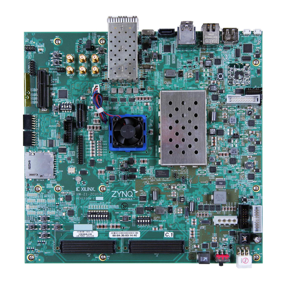
- Page 4 Xilinx ZCU102 Board Page 4 © Copyright 2016 Xilinx...
-
Page 5: Hardware Requirements
Hardware Requirements Maxim MAXPOWERTOOL002# USB-to-PMBus interface dongle – Maxim Part Number: MAXPOWERTOOL002# Page 5 © Copyright 2016 Xilinx... -
Page 6: Software Requirements
Software Requirements Maxim Digital Power Tool – Maxim File name: MaximDigitalPowerTool_V2.00.01.exe (version subject to change – use latest version available on Maxim website) – Download: Latest Release at http://www.maximintegrated.com/en/design/tools/applications/evkit- software/index.mvp?id=1183/ Page 6 © Copyright 2016 Xilinx... -
Page 7: Software Setup
Software Setup Install the Maxim Digital Power Tool Page 7 © Copyright 2016 Xilinx... - Page 8 Connect Maxim Dongle On the Maxim Dongle – Connect the Ribbon Cable – Connect the USB Cable Page 8 © Copyright 2016 Xilinx...
- Page 9 Connect Maxim Dongle Connect the Ribbon Cable to the ZCU102 (J84) – Red Stripe towards pin 1 – Insert the “A” end of the USB cable into a PC USB port (do not use a docking station or USB hub port) –...
- Page 10 – This will automatically start scanning the power rails Please verify that there are a total of 14 voltage rails shown, and all except 0x1A and 0x1B voltage rails are disabled (“Enabled” LEDs turn red) Page 10 © Copyright 2016 Xilinx...
- Page 11 Check Voltage Levels Using the Maxim PowerTool, check that you see the following (voltages inhibited) The Power Good LEDs on the ZCU102 will not light up green upon power-up Page 11 © Copyright 2016 Xilinx...
- Page 12 Restoring Power Levels Unzip the file appropriate to the rev of the ZCU102 you have: – ZCU102 Rev A: FULL_ZCU102_REVA_ONLY_02172016_FINE_CAL_10904.xml – ZCU102 Rev B, C, D: FULL_ZCU102_REVB-D_02172016_FINE_CAL_10904.xml Open the MaximDigitalPower GUI Verify that all power rails are listed in the GUI: –...
- Page 13 Expand the Maxim GUI so that you can see the “Load Configuration” button on the GUI Click “Load Configuration” and browse to where you have saved the appropriate XML file Load the XML file Page 13 © Copyright 2016 Xilinx...
- Page 14 A “Task completed, devices will be reloaded” dialog box will appear indicating that the XML file has been loaded in all of the devices Click “OK” and the GUI will rescan all of the regulators on the board and repopulate them Page 14 © Copyright 2016 Xilinx...
- Page 15 Maxim PowerTool You might need to click the “Search for Devices” button to refresh the controller information Page 15 © Copyright 2016 Xilinx...
- Page 16 – You should press “cancel”, and it will avoid updating the MAX20751 – Why? The supplied XML file only addresses the MAX15303 devices, so no need to waste a write cycle for the MAX20751 on this board IMPORTANT: Do not power off the board Page 16 © Copyright 2016 Xilinx...
- Page 17 – Note that the VFMC_ADJ_10A (located at 0x18) voltage rail will remain disabled – this is by design Verify that all Power Good LEDs on the ZCU102 are on Verify that the FPGA power good LED is green Open the Maxim PowerTool GUI to verify the correct voltages on 12V (Input Voltage) and all FPGA rails (Output Voltage) –...
Need help?
Do you have a question about the ZCU102 and is the answer not in the manual?
Questions and answers