Xilinx ZCU102 Tutorial
System controller – gui
Hide thumbs
Also See for ZCU102:
- User manual (137 pages) ,
- Software install and board setup (41 pages) ,
- Manual (17 pages)
Advertisement
Quick Links
Advertisement

Related Manuals for Xilinx ZCU102


Summary of Contents for Xilinx ZCU102
- Page 1 ZCU102 System Controller – GUI Tutorial May 2019 XTP433...
-
Page 2: Revision History
NOTICE OF DISCLAIMER: The information disclosed to you hereunder (the “Information”) is provided “AS-IS” with no warranty of any kind, express or implied. Xilinx does not assume any liability arising from your use of the Information. You are responsible for obtaining any rights you may require for your use of this Information. - Page 3 Overview Xilinx ZCU102 Board ˃ Updating the Firmware ˃ ZCU102 SCUI ˃ Clocks Voltages Power GTR MUX EEPROM Data GPIO Commands System Monitor About References ˃ Note: This presentation applies to the ZCU102...
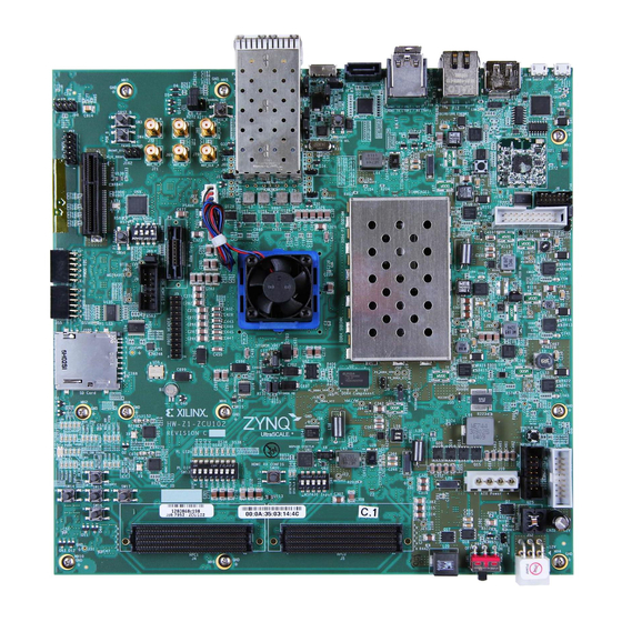
- Page 4 Xilinx ZCU102 Board Note: Presentation applies to the ZCU102...
- Page 5 ZCU102 Software Install and Board Setup Refer to XTP435 – ZCU102 Software Install and Board Setup for details on: ˃ Software Requirements ZCU102 Board Setup Note: Presentation applies to the ZCU102...
- Page 6 ZCU102 System Controller Files Open the RDF0382 – ZCU102 System Controller GUI (2019.1 C) ZIP file ˃ Extract these files to your C:\ drive Note: Presentation applies to the ZCU102...
-
Page 7: Updating The Firmware
Updating the Firmware... - Page 8 Updating the Firmware This System Controller GUI requires the latest version of firmware ˃ Xilinx recommends all ZCU102 users update their MSP430 firmware to the ˃ latest version You can determine the firmware version by opening a Terminal, connected ˃...
- Page 9 Updating the Firmware In this terminal, after power on, type: ˃ @ver The timestamp of the firmware will appear ˃ Any firmware with a timestamp before Jul 5 2017 should be updated ˃ Note: Presentation applies to the ZCU102...
- Page 10 Updating the Firmware To update the firmware, attach two jumpers across J164 as shown ˃ Note: Presentation applies to the ZCU102...
- Page 11 Updating the Firmware Note: Some older ZCU102 boards, such as ˃ Rev D.2, do not have J164. For these boards, connect two long jumpers: From J87 (PMOD1), Pin 1 to J92, Pin 11 From J87 (PMOD1), Pin 3 to J92, Pin 8...
- Page 12 Updating the Firmware Run the BIT.exe from C:\zcu102_scui\flash_restore ˃ Note: Close the Terminal Window before restoring flash...
- Page 13 Running the System Controller GUI...
- Page 14 Running the System Controller GUI From C:\zcu102_scui, double click on BoardUI.exe ˃ Enter the board serial number and MAC ID ˃ Click OK ˃ Note: Presentation applies to the ZCU102...
- Page 15 Clocks...
-
Page 16: Setting The Clocks
Setting the clocks Select the Set tab underneath the Clocks tab ˃ Enter 156.25 for the Si5328 and click the Set Si5328 Frequency button ˃ (takes a long moment to complete) Note: Presentation applies to the ZCU102... - Page 17 Reading the clocks Select the Read tab ˃ Click each of the Read buttons and verify the frequencies are set as shown ˃ Note: Presentation applies to the ZCU102...
- Page 18 Reading the clocks If some of the frequencies show up different, you will need to restore the ˃ defaults Note: Presentation applies to the ZCU102...
- Page 19 Restore Default Clock settings Select the Restore Device Defaults tab ˃ Restore the defaults by clicking the button associated with the clock you ˃ want to restore (300 MHz, 156.25 MHz, and 0 MHz) Note: Presentation applies to the ZCU102...
- Page 20 Restore Default Clock settings Return to the Read tab and verify the settings are correct ˃ Note: Presentation applies to the ZCU102...
- Page 21 Setting Clock Boot Frequencies Select the Set Boot Frequency tab ˃ Type in your desired boot-up frequency and click the corresponding Set ˃ button Note: Presentation applies to the ZCU102...
- Page 22 Note: The Set Boot Frequency settings will override the Restore Device ˃ Defaults at Bootup The example designs, IBERT, IPI, MIG, etc., expect Si570 User set to 300 ˃ MHz, and Si570 MGT/Si5328 set to 156.25 MHz Note: Presentation applies to the ZCU102...
- Page 23 Voltages...
- Page 24 Reading onboard ZCU102 voltages Under the Voltages tab, ˃ click the Run all checked buttons button Observe the ZCU102 ˃ voltages...
- Page 25 Power...
- Page 26 Reading power values using default calibration Select the Use Default ˃ Calibration tab underneath Power Under the PS Side tab, ˃ click the Run all button...
- Page 27 Reading power values using default calibration Under the PL Side tab, click the Run all button ˃...
- Page 28 Read INA226 Registers Select the Get INA226 ˃ Registers tab Under the PS Side tab, ˃ click the Run all button and observe the INA226 Registers settings...
- Page 29 Read INA226 Registers Select the Get INA226 ˃ Registers tab Under the PL Side tab, ˃ click the Run all button and observe the INA226 Registers settings...
- Page 30 Set INA226 Registers Select the Set INA226 ˃ Registers tab Under the PS Side tab, ˃ set any desired calibrations Review TI INA226 ˃ documentation before making changes...
- Page 31 Set INA226 Registers Select the Set INA226 ˃ Registers tab Under the PL Side tab, ˃ set any desired calibrations Review TI INA226 ˃ documentation before making changes...
- Page 32 Reading power values using custom calibration Select the Use Custom ˃ Calibration tab Under the PS Side tab, ˃ click the Run all checked buttons button (no calibrations were entered in this example)
- Page 33 Reading power values using custom calibration Select the Use Custom ˃ Calibration tab Under the PL Side tab, ˃ click the Run all checked buttons button (no calibrations were entered in this example)
- Page 35 Under the Current tab, select the desired VADJ voltage ˃ PL MIG requires a voltage (1.2 to 1.8V) to operate ˃ BIT (XTP428) will force VADJ to 1.8 V for any test that needs VADJ ˃ Note: Presentation applies to the ZCU102...
- Page 36 Set Boot-Up VADJ Select the Boot-up tab and choose the desired power-on voltage ˃ The default, Use FMC EEPROM Voltage, will set 1.8 V unless you attach an ˃ FMC card with a different setting Note: Presentation applies to the ZCU102...
- Page 37 Reading FMC EEPROM Select the HPC0 or HPC1 tab depending on which FMC slot your FMC card ˃ is attached to Click the Get EEPROM Data button ˃ Note: Presentation applies to the ZCU102...
- Page 38 Reading FMC EEPROM The EEPROM data will be displayed in a separate window (XM107 data ˃ shown) Note: Presentation applies to the ZCU102...
- Page 39 Setting FMC HPC clocks With an optional XM107 FMC card attached, select the XM107 tab ˃ For the IBERT FMC testing, set 163, and click the Set SI570 button ˃ Note: Presentation applies to the ZCU102...
- Page 40 GTR MUX...
- Page 41 Set GTR MUX Select the GTR MUX tab ˃ Click the corresponding button for the desired setting ˃ Note: Presentation applies to the ZCU102...
-
Page 42: Eeprom Data
EEPROM Data... - Page 43 Reading the Board EEPROM Data Select the EEPROM Data tab ˃ Click the Get All EEPROM Data button ˃ Note: Presentation applies to the ZCU102...
-
Page 44: Gpio Commands
GPIO Commands... - Page 45 Set GPIOs Select the GPIO Commands tab ˃ Click the button for the operation you would like to perform. ˃ Note: Presentation applies to the ZCU102...
-
Page 46: System Monitor
System Monitor... - Page 47 This test requires a bitstream with System Monitor; you can use the BIST ˃ bitstream from the QSPI – see XTP434 for details Select Temperatures tab under the System Monitor tab and click Run all ˃ Note: Presentation applies to the ZCU102...
- Page 48 Reading the FPGA System Monitor Voltages This test requires a ˃ bitstream with System Monitor; you can use the BIST bitstream from the QSPI – see XTP434 for details Select the System ˃ Monitor tab Click Run All and ˃ observe the readings...
- Page 49 About...
- Page 50 Reading version information Select the About tab ˃ Click the Get Version button to get MSP430 Firmware version ˃ Note: Presentation applies to the ZCU102...
- Page 51 File Changes...
- Page 52 File changes If you make changes some of the *.yaml files, you may get this warning. ˃ Select Update Checksums and restart GUI to resolve.
- Page 53 References...
- Page 54 References Vivado Release Notes ˃ Vivado Design Suite User Guide - Release Notes – UG973 https://www.xilinx.com/support/documentation/sw_manuals/xilinx2019_1/ ‒ ug973-vivado-release-notes-install-license.pdf Vivado Design Suite 2019 - Vivado Known Issues https://www.xilinx.com/support/answers/72162.html ‒ Vivado Programming and Debugging ˃ Vivado Design Suite Programming and Debugging User Guide – UG908 https://www.xilinx.com/support/documentation/sw_manuals/xilinx2019_1/...
- Page 55 Documentation...
- Page 56 Xilinx Zynq UltraScale+ MPSoC ZCU102 Evaluation Kit https://www.xilinx.com/products/boards-and-kits/ek-u1-zcu102-g.html ‒ ZCU102 Board User Guide – UG1182 ‒ https://www.xilinx.com/support/documentation/boards_and_kits/zcu102/ ug1182-zcu102-eval-bd.pdf ZCU102 Evaluation Kit Quick Start Guide User Guide – XTP426 ‒ https://www.xilinx.com/support/documentation/boards_and_kits/zcu102/ xtp426-zcu102-quickstart.pdf ZCU102 - Known Issues Master Answer Record ‒ https://www.xilinx.com/support/answers/66752.html...
Need help?
Do you have a question about the ZCU102 and is the answer not in the manual?
Questions and answers