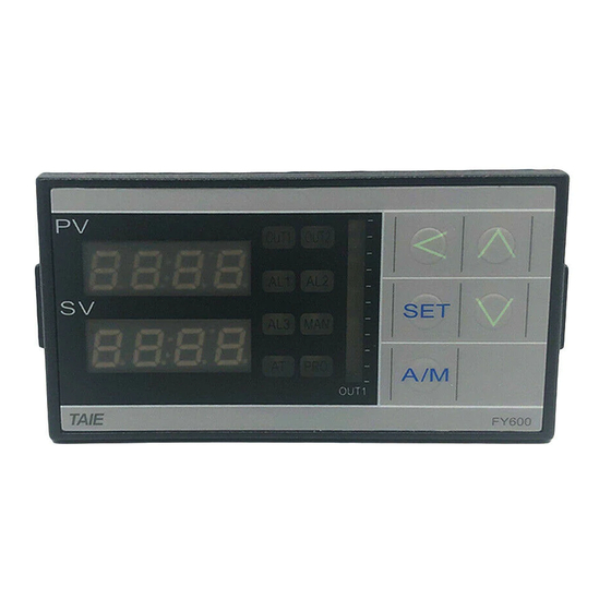
Taie FY400 Operation Manual
Digital temperature controller
Hide thumbs
Also See for FY400:
- Operation manual (105 pages) ,
- Communications manual (28 pages) ,
- Operation manual (66 pages)


Need help?
Do you have a question about the FY400 and is the answer not in the manual?
Questions and answers