
Subscribe to Our Youtube Channel
Related Manuals for Taie FY100


Summary of Contents for Taie FY100
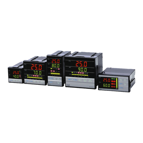
- Page 1 COMMUNICATION MANUAL DIGITAL PID CONTROLLER FY100 FY101 FY400 FY600 FY700 FY800 FY900 February, 2007 FY_COMM_EN_V1 TAIE TAIWAN INSTRUMENT & CONTROL CO., LTD...
-
Page 3: Table Of Contents
Setting (Set SV = 10.0 to slave controller 1) .........8 5.7.2 Setting (Set SV = 10.0 and OUTL=100.0 to slave controller 1)..9 TAIE Protocol ......................10 Message Configuration ................10 Command....................10 ID Number ....................10 Register Address ..................10 Data ......................10 Check Sum ....................11 Message example of TAIE Protocol ............11... - Page 4 6.7.1 Read ( Read PV from slave controller 1)........11 6.7.2 Modify ( Modify SV = 10.0 to slave controller 1)....... 11 6.7.3 Write ( Write SV = 100.0 to slave controller 1) ......11 Register Map......................12...
-
Page 5: Set Up Of The Controller
Protocol Selection : MODBUS RTU Protocol : MODBUS ASCII Protocol : TAIE Protocol Communication Bits : Odd parity , Data bits = 8 , Stop Bit = 1 :Odd parity , Data bits = 8 , Stop Bit = 2... -
Page 6: System Configuration
2 System Configuration 2 System Configuration 2.1 RS485 Communication System Contoller Controller Controller Controller (RS-485) ………… IDNO : 2 IDNO : 3 IDNO : 4 IDNO : 32 Figure: 2.1-1 (RS-485) Controller Controller Controller Controller ………… IDNO : 1 IDNO : 2 IDNO : 3 IDNO : 32 Figure: 2.1-2... -
Page 7: Wiring Connection
3 Wiring Connection 3 Wiring Connection 3.1 RS485 Communication Wiring RS485 Converter Controllers DX - Shield Wire DX + (T+) (T-) (R-) TxON (R+) RxON MODEL : IC485SN DX - DX + Figure: 3.1-1 RS485 Converter Controllers DC24V DX - DX + Shield Wire DATA-... -
Page 8: Modbus Rtu Protocol
4 MODBUS RTU Protocol 4 MODBUS RTU Protocol 4.1 Message Configuration ID Number Function Code Data 1 Byte 1 Byte N Byte 2 Byte 4.2 ID Number (Slave Address) Range: 1~255. Master instrument identifies slave controllers by the ID Number of the requested message. -
Page 9: Abnormal Code
4 MODBUS RTU Protocol ⑧ . Repeat step 3~5, until last data is processed. ⑨ . Swap the low byte and high byte of Y. ⑩ . CRC=Y 4.6 Abnormal Code Abnormal Code Contents 01 (01H) Illegal function code (Non-existent function code) 02 (02H) Illegal register address (Register address is out of range) 03 (03H) -
Page 10: Setting (Set Sv = 10.0 And Outl=100.0 To Slave Controller 1)
4 MODBUS RTU Protocol Response from slave controller in abnormal status (Assumed as illegal data value) ID Number Function Code Error Code (01H) (86H) (03H) (0261H) 1 is set to the MSB of function code in abnormal status (86H). The abnormal code (03H) is returned as contents of error. 4.7.3 Setting (Set SV = 10.0 and OUTL=100.0 to slave controller 1) Request message from master instrument:... -
Page 11: Modbus Ascii Protocol
5 MODBUS ASCII Protocol 5 MODBUS ASCII Protocol 5.1 Message Configuration Header ID Number (Function Code) Data Delimiter (CR+LF) 1 Byte 2 Byte 2 Byte 2N Byte 2 Byte 2 Byte 5.2 ID Number(Slave Address) Range: 1~255 Master instrument identifies slave controllers by the ID Number of the requested message. -
Page 12: Abnormal Code
5 MODBUS ASCII Protocol 5.6 Abnormal Code Abnormal Code Contents 01 (30H 31H) Illegal function code (Non-existent function code) 02 (30H 32H) Illegal register address (Register address is out of range) 03 (30H 33H) Illegal data value (Data value is out of setting range) 5.7 Message example of ASCII mode Reading ( Read PV from slave controller 1) Request message from master instrument:... -
Page 13: Setting (Set Sv = 10.0 And Outl=100.0 To Slave Controller 1)
5 MODBUS ASCII Protocol Response from slave controller in abnormal status (Assumed as illegal data value) Header ID Number Function Error Code Delimiter Code (3AH) (30H 31H) (38H 36H) (30H 33H) (37H 36H) (0DH 0AH) 1 is set to the MSB of function code in abnormal status (86H). The abnormal code (03H) is returned as contents of error. -
Page 14: Taie Protocol
6 TAIE Protocol 6 TAIE Protocol 6.1 Message Configuration Master Slave (7 Bytes): Command ID Number Register Data Check Sum Address 1 Byte 1 Byte 2 Byte 2 Byte 1 Byte Master Slave (8 Bytes) Header Command ID Number Register... -
Page 15: Check Sum
Add all the values from “Command” to the end of “Data”. The result is Check Sum (1 byte). EX:52H + 01H + 00H +8AH +00H +00H = DDH 6.7 Message example of TAIE Protocol 6.7.1 Read ( Read PV from slave controller 1) - Page 16 7 Register Map 7 Register Map MODBUS Register Address Parameters Setting Range Function Code DECIMAL 0000 03/06/10H Set Point OUTL 0001 03/06/10H 0 ~ 1000 Output Limit 0000H=NO 0002 03/06/10H Auto Tuning 0001H=YES 0003 03/06/10H Alarm 1 set value 0004 03/06/10H Alarm 2 set value 0005...
- Page 17 7 Register Map MODBUS Register Address Parameters Setting Range Function Code DECIMAL TM_2 Run Time of Seg.2 000D 03/06/10H (Pattern 1) OUT2 Output Limit of Seg.2 000E 03/06/10H (Pattern 1) SV_3 Set Point of Seg.3 000F 03/06/10H (Pattern 1) TM_3 Run Time of Seg.3 0010 03/06/10H...
- Page 18 7 Register Map MODBUS Register Address Parameters Setting Range Function Code DECIMAL TM_6 Run Time of Seg.6 0019 03/06/10H (Pattern 1) OUT6 Output Limit of Seg.6 001A 03/06/10H (Pattern 1) SV_7 Set Point of Seg.7 001B 03/06/10H (Pattern 1) TM_7 Run Time of Seg.7 001C 03/06/10H...
- Page 19 7 Register Map MODBUS Register Address Parameters Setting Range Function Code DECIMAL TM_22 Run Time of Seg.2 0025 03/06/10H (Pattern 2) OUT22 Output Limit of Seg.2 0026 03/06/10H (Pattern 2) SV_32 Set Point of Seg.3 0027 03/06/10H (Pattern 2) TM_32 Run Time of Seg.3 0028 03/06/10H...
- Page 20 7 Register Map MODBUS Register Address Parameters Setting Range Function Code DECIMAL TM_62 Run Time of Seg.6 0031 03/06/10H (Pattern 2) OUT62 Output Limit of Seg.6 0032 03/06/10H (Pattern 2) SV_72 Set Point of Seg.7 0033 03/06/10H (Pattern 2) TM_72 Run Time of Seg.7 0034 03/06/10H...
- Page 21 7 Register Map MODBUS Register Address Parameters Setting Range Function Code DECIMAL HYS1 003F 03/06/10H 0~1000 OUT1 Hysteresis 0040 03/06/10H 0~2000 OUT2 Proportional Band 0041 03/06/10H 0~3600 OUT2 Integral Time 0042 03/06/10H 0~900 OUT2 Derivative Time CYT2 0043 03/06/10H 0~150 OUT2 Cycle Time HYS2 0044...
- Page 22 7 Register Map MODBUS Register Address Parameters Setting Range Function Code DECIMAL INP1 0048 03/06/10H 000EH = S1 Input Type Selection 000FH = S2 0010H = B1 0011H = E1 0012H = E2 0013H = N1 0014H = N2 0015H = T1 0016H = T2 0017H = T3 0018H = W1...
- Page 23 7 Register Map MODBUS Register Address Parameters Setting Range Function Code DECIMAL INP1 0048 03/06/10H 0032H = JP.6 Input Type Selection 0033H = AN1 0034H = AN2 0035H = AN3 0036H = AN4 0037H = AN5 ANL1 Linear Input Zero 0049 03/06/10H Calibration...
- Page 24 7 Register Map MODBUS Register Address Parameters Setting Range Function Code DECIMAL ALT3 0055 03/06/10H Alarm time for AL3 HYSA 0056 03/06/10H 0000H=0000 Hysteresis for all Alarms 0001H=0000 0010H=0010 0011H=0011 0100H=0100 0101H=0101 0110H=0110 0111H=0111 1000H=1000 1001H=1001 1010H=1010 1011H=1011 1100H=1100 1101H=1101 1110H=1110 1111H=1111 CLO1...
- Page 25 7 Register Map MODBUS Register Address Parameters Setting Range Function Code DECIMAL SETA 005F 03/06/10H 0060 Protocol Selection BITS 0061 Communication Bits IDNO 0062 0~255 ID Number BAUD 0063 Baud rate SVOS 0064 03/06/10H SV Compensation PVOS 0065 03/06/10H PV Compensation 0000H=C UNIT Unit of PV and SV...
- Page 26 7 Register Map MODBUS Register Address Parameters Setting Range Function Code DECIMAL SET1 006C 03/06/10H 1000H=1000 Hide/ Display parameter 1001H=1001 1010H=1010 1011H=1011 1100H=1100 1101H=1101 1110H=1110 1111H=1111 SET2 006D 03/06/10H Same with SET1 Hide/ Display parameter SET3 006E 03/06/10H Same with SET1 Hide/ Display parameter SET4 006F...
- Page 27 7 Register Map MODBUS Register Address Parameters Setting Range Function Code DECIMAL 0086 Firmware Version OUT% 0087 0~1000 Output percentage OBIT 0088 0000 0000 0000 0000 Controller Information : Message nnn2 : Message UUU2 : Message nnn1 : Message UUU1 : Message IN2E : Message CJCE : Message ADCF...
- Page 28 TAIE TAIWAN INSTRUMENT & CONTROL CO., LTD FY400/600/700/800/900 COMMUNICATION MANUAL...
Need help?
Do you have a question about the FY100 and is the answer not in the manual?
Questions and answers