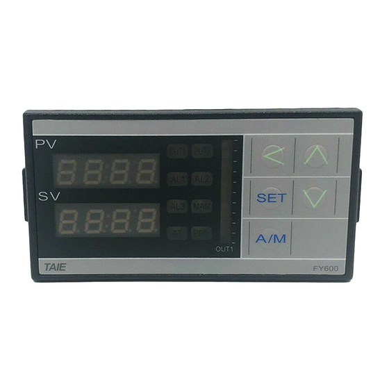
Taie FY400 Operation Manual

Taie FY400 Operation Manual

Digital temperature controller
Hide thumbs Also See for FY400:

Advertisement

Digital Temperature Controller
FY400/600/700/800/900
FU400/FU48/72/86/96
Operation Manual
台 灣 儀 控 股 份 有 限 公 司
TAIWAN INSTRUMENT & CONTROL CO., LTD
Ver 1.0

Advertisement

Table of Contents
loading

Summary of Contents for Taie FY400

  • Page 1 Digital Temperature Controller FY400/600/700/800/900 FU400/FU48/72/86/96 Operation Manual Ver 1.0 台 灣 儀 控 股 份 有 限 公 司 TAIWAN INSTRUMENT & CONTROL CO., LTD...
  • Page 2: Table Of Contents

    FY700/FU72 Dimensions ........................10 FY800/FU86 Dimensions ........................11 FY900/FU96 Dimensions ........................11 8. Terminal Arrangement ............................ 12 FY400/FU400/FU48 Terminal Arrangement …..................12 FY600 Terminal Arrangement ......................13 FY700/FU72 Terminal Arrangement ....................14 FY800/FU86 Terminal Arrangement ....................15 FY900/FU96 Terminal Arrangement ....................16 9.
  • Page 3 10.10 Level 4 (Setting Level) All Parameters Display ................28 10.11 LEVEL_4 Parameters ..................... 10.12 Parameters Hide/Display Table on level 4 ........10.13 Fast Parameter Access ................... Functional Descriptions .................... 11.1 PV bias ..........................11.2 Retransmission ....................... 11.3 Remote SV ..........................
  • Page 4 18. FY Communication Register Address Table ......................19. Glossary of Characters Used In This Manual ....................... FY/FU operation manual...
  • Page 5: Notice

    1. Notice Warning 1. Beware of Electric Shock! 2. Once controller is activated, do not touch AC power wiring terminals to avoid electric shock! 3. First to confirm power is OFF, before working on the wiring of controller power supply! 4.
  • Page 6: Specifications

    Resolution 18 bit valve controlled by Interface RS-485 Half duplex Communication MAX. 31 units, MAX. distance 1200 meters Protocol Modbus RTU , TAIE Comm Parity bit NONE, ODD, EVEN unicati Data bit 8 bit Stop bit 1 or 2 bit...
  • Page 7: Input Range Table

    0~1V 0~2V -1.999~9.999 0~5V -19.99~99.99 Linear 0~10V -199.9~999.9 -1999~9999 0~70mV 4~20mA 10~50mV 1~5V 2~10V 5. Packing List & Label Information 5.1 Packing List Guide FY400/600/700/800/900 1. Temperature Controller…1 unit 2. Mounting frame………….2 units 3. Brief manual……………..1 pcs FY/FU operation manual...
  • Page 8: Label Guide

    5.2 Label Guide 5.2.1 FY400/FU400/FU48 Terminal arrangement FY400 Terminal Wiring Diagram Model number FY400 model name Serial number 18112740001 Input type Controller Input Signal and Scope 5.2.2 FY700/FU72 Terminal arrangement FY700 Terminal Wiring Diagram Model number FY700 model name Serial number...
  • Page 9 5.2.3 FY600/800/900/FU86/96 Terminal arrangement FY900 Terminal Wiring Diagram Model number FY900 model name Serial number 18112790001 Input type Controller Input Signal and Scope FY/FU operation manual...
  • Page 10: Parts Description

    8.8.8.8 8.8.8.8 8.8.8.8 8.8.8.8 8.8.8.8 8.8.8.8 8.8.8.8 8.8.8.8 8.8.8.8 8.8.8.8 FY400/FU400 FY900/FU96 FY800/FU86 FY700/FU72 FY600 Indicating PV (measured value) and character information such as parameter codes or error codes(Red) Indicating SV (target set value) or parameter values(Green) Lamp lit when OUT1 is activated...
  • Page 11: Fy400/Fu400/Fu48 Dimensions

    7. Installation 7.1 FY400/FU400/FU48 Dimensions (Unit: mm) 7.2 FY600 Dimensions (Unit: mm) Mounting fixture t (panel thickness) 1~t~6 7.3 FY700/FU72 Dimensions (Unit: mm) Dimensions Individual mounting FY/FU operation manual...
  • Page 12: Fy800/Fu86 Dimensions

    7.4 FY800/FU86 Dimensions (Unit: mm) Dimensions Individual mounting 7.5 FY900/FU96 Dimensions (Unit: mm) Dimensions Individual mounting FY/FU operation manual...
  • Page 13: Terminal Arrangement

    Do not touch the live parts, such as the terminals, while the power is on. Otherwise death or serious injury may be resulted from short circuit of the contact electrode. FY400/FU400/FU48 Terminal Arrangement Power supply AC 85~265V...
  • Page 14: Fy600 Terminal Arrangement

    FY600 Terminal Arrangement Remote mA/V INPUT mA/V COMM A RTD T/R (B) T/R (A) TC/mV 11 12 18 19 Relay Power supply mA/V Relay AC 85~265V DC 24V OUT2 (AL3) mA/V OUT1 T/R (B) Power Communication AC 85~265V DC 24V RS-485 T/R (A) Transmission...
  • Page 15: Fy700/Fu72 Terminal Arrangement

    FY700/FU72 Terminal Arrangement T/R (B) Power supply AC 85~265V COMM DC 24V T/R (A) OUT2 Relay (AL1) mA/V Relay mA/V INPUT OUT1 mA/V TC/mV RTD mA/V Power AC 85~265V DC 24V Alarm 1 Alarm 2 Alarm 3 Output-1 mA / V T/R (B) Communication RS-485...
  • Page 16: Fy800/Fu86 Terminal Arrangement

    FY800/FU86 Terminal Arrangement Power supply AC 85~265V DC 24V T/R (B) COMM Remote mA/V T/R (A) Relay OUT2 (AL3) mA/V Relay INPUT OUT1 mA/V TC/mV RTD mA/V T/R (B) Power Communication AC 85~265V DC 24V RS-485 T/R (A) Transmission mA / V mA / V Output-1 mA / V...
  • Page 17: Fy900/Fu96 Terminal Arrangement

    FY900/FU96 Terminal Arrangement Power supply T/R (B) AC 85~265V COMM DC 24V T/R (B) COMM Remote mA/V T/R (A) Relay OUT2 (AL3) mA/V Relay NO INPUT OUT1 mA/V mA/V TC/mV RTD mA/V Power AC 85~265V DC 24V CLOSE Motor OPEN valve Output-1 mA / V...
  • Page 18: Basic Function Setting

    9. Basic Function Setting 9.1 Input Type Setting Hold key + key 3 seconds, to enter LEVEL_3 “INP1” with lower display showing current input type. Press key and Press key the lower display flashes. input type. Modify input type needs to interchange of jumper location, Press key to store new and it needs to recalibration for linear input type change.
  • Page 19: On/Off Control Setting

    9.5 ON/OFF Control Setting Hold key 3 seconds, then entering into LEVEL_2, Display after power-on. as upper display shows “P1”, with lower display showing current P1 value. When key is pressed, Press key until the lower display flashes, P1 = 0.0 upper display.
  • Page 20: Manual Mode Selection

    9.8 Manual Mode Selection 2 seconds. Press key and When key is pressed, key to set the intended the lower display flashes. output% value. In manual mode OUTL=100.0,output=100.0 % Press key to store new continuously. value. In manual mode OUTL=20.0,output=20.0 % continuously.
  • Page 21: Level Operation Diagram

    10.2 Level Operation Diagram Level 3 (Input Level) press SET + key 3 seconds press SET key press SET + 3 seconds 3 seconds press SET key 3 seconds Level 2 Level 1 Power ON (PID Level) (User Level) press SET key LCK = 1111, press SET + 3 seconds 3 seconds...
  • Page 22: Level 1 (User Level) All Parameters Display

    10.4 Level 1 (User Level) All Parameters Display Level 1 Press SET key PV / SV OUTL Output percentage Auto tuning AL1/SOAK/HBAC AL1  Alarm1 set value SOAK  Alarm1 soak time HBAC HBA current setting value AL2/SOAK/HBAC AL2  Alarm2 set value SOAK ...
  • Page 23: Level_1 Parameter

    10.5 LEVEL_1 Parameter Range Hide/ Parameter Symbol Content Default Display LSPL LSPL High limit setting of manipulated value main output OUTL 100.0 100.0 SET1.1 when PID gain > OUTL use OUTL as manipulated value Auto-tuning execute selection 0 : NO PID control SET1.2 1 : YES execute auto tuning Alarm1 set value...
  • Page 24: Level 2 (Pid Level) All Parameters Display

    10.6 Level 2 (PID Level) All Parameters Display Level 2 Press SET key CYT2 HYS2 Main output Hysteresis for o i t GAP1 integral time (for main output) GAP2 derivative time (for sub output) AT.VL s f f o i t CYT1 Main output control cycle...
  • Page 25: Level_2 Parameter

    10.7 LEVEL_2 Parameter Range Hide/ Default Display Main output proportional band 0.0 : ON/OFF control 200.0 Other values : proportional band setting value Main output integral time 0 : disable integral function 3600 Other values : integral time setting value Main output derivative time 0 : disable derivative function Other values : derivative time setting value...
  • Page 26: Level 3 (Input Level) All Parameters Display

    10.8 Level 3 (Input Level) All Parameters Display Level 3 Press SET key ALT1 CLO3 PVOS CHO3 UNIT Retransmission Alarm2 mode selection Input unit input type selection span calibration PVFT ANL1 ALT2 RHTC/RUCY main input RHTC  Dehumidification temperature PV digital filter Alarm2 time setting RUCY ...
  • Page 27 10.9 LEVEL_3 Parameter Range Hide/ Default Display LSPL Input scale low 9999 -1999 SET2.3 USPL Input scale high 9999 -1999 SET2.3 ANL2 Sub input zero calibration 9999 -1999 SET2.4 ANH2 Sub input span calibration (hex display) 0x7FFF 0x0000 0x5FFF SET2.4 Alarm1 mode selection ALD1 SET3.1...
  • Page 28 Alarm special function setting SETA 1111 0000 0000 SET5.3 (Please refer to Chapter 12.2) Protocol selection 0 : TAIE TAIE SET5.4 1 : RTU (Please refer to communication manual) Data format 0 : O_81 (parity bit=odd, stop bit=1) 1 : O_82...
  • Page 29: Level 4 (Setting Level) All Parameters Display

    10.10 Level 4 (Setting Level) All Parameters Display Level 4 Press SET key SET0 SET1 INP2 Parameters sub input type selection Hide/Display SET2 OUTY SET3 PROG Hide/Display enable SET4 SET1 Parameters Hide/Display SET5 Parameters Hide/Display SET6 Parameters Hide/Display SET7 Parameters Hide/Display SET8 Parameters...
  • Page 30 10.11 LEVEL_4 Parameter Range Hide/ Default Display SET0 - - - Sub input type selection 0 : none 1 : 10~50mV / 4~20mA / 1~5V / 2~10V (remote SV use) INP2 2 : 0~50mV / 0~20mA / 0~5V / 0~10V (remote SV use) 3 : valve feedback 4 : CT input...
  • Page 31 Hide CLO2 CHO2 SET5_1 Display CLO2 CHO2 Hide CLO3 CHO3 SET5_2 Display CLO3 CHO3 Hide RUCY WAIT SETA SET5_3 Display RUCY WAIT SETA Hide PSL BITS IDNO BAUD SET5_4 Display PSL BITS IDNO BAUD Hide SVOS SET6_1 Display SVOS Hide PVOS SET6_2 Display...
  • Page 32: Fast Parameter Access

    10.13 Fast Parameter Access FY controller provides a fast parameter access operation, easy for users to quickly access communication group, program group, motor valve group related parameters Enter fast parameter access operation: press down key for 3 seconds at any level Leave fast parameter access operation: press down key for 3 seconds at fast parameter access operation Any Level Press...
  • Page 33: Functional Descriptions

    11. Functional Descriptions 11.1 PV bias Description The FY series controller offers PV bias for input calibration, PV bias functions correct the deviation of each sensor, as well as PV difference between controllers. Function Diagram PV bias Temperature 200° C 198°...
  • Page 34: Retransmission

    4~20mA, 0~20mA, 0~5V, 0~10V, 1~5V, 2~10V Function Diagram 100.0 200.0 Sensor input Retransmission output OUT1 OUT2 ATAL1 A L2 AL3M AN OUT1 SET A/M Electric furnace TAIE FY900 12.00 Sensor ammeter Parameter Range Hide/ Parameter Symbol Content Default Level 0 : Retransmission SV disable SET9.3...
  • Page 35: Remote Sv

    Remote SV terminal of the controller, to change the SV with a preset range. Remote SV signal selection: 4~20mA, 0~20mA, 0~5V, 0~10V, 1~5V, 2~10V Function Diagram 50.0 100.0 OUT1 OUT2 Sensor input Remote SV input OUT1 TAIE FY900 20.00 Control Electric output furnace PLC AO module / transmitter Power...
  • Page 36: Heater Break Alarm

    Function Diagram KBA( 10.0 Sensor input OUT1 OUT2 ATAL1 AL2AL3 MANPRO OUT1 HBA alarm 80100 SET A/M TAIE FY900 Control output SC 80-T Heater AC power nsor Electric furnace Parameter Range Hide/ Parameter Symbol Content...
  • Page 37 Notes 1. ANL2 & ANH2 is the current signal calibration parameters. It has been calibrated before leaving the factory. Do not change this parameter value. 2. The user only needs to set HBAC, the rest of the parameters will be set & calibrated at the factory. 3.
  • Page 38: Dehumidification Function

    11.5 Dehumidification Function Description The FY controller provides dehumidification function to protect the heater. When the power is turned on, the heater is dehumidified with low power. When the dehumidification is completed, the normal power is output to the heater. Function Diagram PV <...
  • Page 39: Motor Valve Control

    11.6 Motor Valve Control Function Diagram Motor valve FY600/800/900 Controller CLOSE CLOSE OPEN feedback (NFMV) OPEN ball valve:Low pressure, general use needle valve:High pressure, High precision use FY600/800/900 Motor valve Controller CLOSE 14 CLOSE 1KΩ WIPER signal feedback OPEN OPEN CLOSE CLOSE feedback...
  • Page 40 Parameter Setting Level Parameter Set value Description Valve control, no feedback OUTY Valve control, feedback INP2 Valve control, feedback Motor valve operating time *RUCY (set the operating time according to the connected valve) ※Set runtime whether there is feedback or no feedback Motor valve switching CYT1 feedback...
  • Page 41: Ramp & Soak

    11.7 RAMP & SOAK Description The FY general- purpose controller provides a single ramp and soak function, after booting completed, the SV starts to increase according to the set value of RAMP. when the soak condition is met the SOAK function will be executed according to the set value of SOAK, and driving the output and alarm to ON or OFF after the SOAK time is executed finish.
  • Page 42 Example(2) Single RAMP+SOAK_B (ALD3=9 + ALD1=19) Boot completed, the alarm1 is OFF, SV rise 5.00°C rise per minute. when the PV reaches 100 °C, the temperature is kept for 10 minutes. after 10 minutes alarm is turned ON and the control function keep ON Parameter setting Level Parameter...
  • Page 43 Example(4) use only SOAK_B (ALD1=19) Boot completed, the alarm1 is OFF, and the PV is directly controlled at 100 °C. when the PV reaches 100 °C, the temperature is kept for 10 minutes. after 10 minutes alarm is turned ON and the control function keep ON Parameter setting Level Parameter...
  • Page 44: Alarm Action

    Users can choose the most suitable alarm mode according to their needs for system protection or application. Function Diagram 100.0 Alarm 1 200.0 OUT1 OUT2AT AL3MAN OUT1 Alarm 2 SET A/M TAIE FY900 Alarm 3 Parameter setting Range Hide/ Parameter Symbol Content Default Level...
  • Page 45: Alarm Mode

    12.1 Alarm Mode :SV : Alarm set value X:1 / 2 / 3 (There are up to 3 sets of alarms) ALDX Alarm mode Description No alarm function Not drive any alarm relays and the corresponding LED lamp. HYSX Deviation high (With hold action) PV ≥...
  • Page 46 12.1 Alarm Mode :SV : Alarm set value X:1 / 2 / 3 (There are up to 3 sets of alarms) Descriptio ALDX Alarm mode Boot completed, the alarm is ON, when PV≥SV start the timer, alarm and control function are turned OFF in timed out. If the RAMP function is used, even if the RAMP SV has not reached the target SV, the timer will start counting as long as the SOAK_A...
  • Page 47: Alarm Special Setting

    12.1 Alarm Mode ALDX Alarm mode Description Boot completed, the alarm is OFF, when PV≥SV start the timer, alarm is turned ON and the control function keep ON in timed out. If the RAMP function is used, even if the RAMP SV has not reached the target SV, the timer will start counting as long as the SOAK_B condition PV≥target SV is met.
  • Page 48: Programmable

    13. Programmable Description Programmable function is SV function that is variable to time, as user can set SV value to their needs according to time- based variation curve, which is called program setting 1. There are at most 18 sets of pattern setting 2.
  • Page 49: Key Operation Description

    13.1 Parameter Setting Range Hide/ Parameter Symbol Content Default Level Display SV_4 Level 1 PROG=ON TM_4 Segment 4 execute time setting 99.59 0.00 Level 1 PROG=ON OUT4 Segment 4 output limit 100.0 100.0 Level 1 PROG=ON SV_5 Level 1 PROG=ON TM_5 Segment 5 execute time setting 99.59...
  • Page 50: Program Initial Setting

    13.3 Program Initial Setting Program Initial Setting Program time format Program execute start address Program execute with repeat function ? Program execute with power fail function ? Program execute with wait function ? Setting program time format Parameter Default Level Program time format SET9.2 1 : minute.second...
  • Page 51: Create Program

    Setting program execute with wait function Parameter Default Level Program execution standby temperature 0 : when program execute do not wait for PV WAIT Other values : when PV=(target SV-WAIT), program entering next segment When program executes, if WAIT=0.0, and SV reaches set temperature, whether PV reaches target temperature or not, the controller will enter the next segment When program executes, if WAIT value is not 0.0, and SV reaches set temperature, as PV has not reached target temperature, controller will wait for PV temperature to reach SV-WAIT...
  • Page 52 Program edit flow-chat START Set PTN SetSV_n SetTM_n SetOUTn Edit next segment Edit next pattern ReturnPV/SV ※ n : 1~8 Choose program pattern number Parameter LED display Description Default Level Setting segment n target SV Parameter Default Level SV_n Setting segment n target TM Parameter Default Level...
  • Page 53: Program Execution Flow

    13.5 Program Execution Flow The program can be up to 18 patterns. If you connect all the patterns, up to 144 segments. link the PTN _1 PTN _2 PTN _18 link the next link the next next patterns patterns patterns SEG_1 SEG_1 SEG_1...
  • Page 54: Modification Of Output Module

    14. Modification of Output Module 14.1 Relay Control (1a) Software Setting Coil OJE-SS-124LMH 250VAC, 8A Parameter set as “CYT1 =10” 14.2 Relay Control (1c) Side view Bottom view Software Setting Coil JQ1P-24V-F Parameter set as “CYT1 =10” 250VAC N.C. N.O. 14.3 SSR Control Software Setting Top view...
  • Page 55 14.5 Output Calibration Proccedure Diagram Output1 Signal (4mA~20mA) calibration flowchart Start Display CLO1 and CHO1 SET4_4=1 CLO1=0 Default Value CHO1=3600 Set controller SV=LSPL low setpoint output%=0% Adjust CLO1 until meter=4mA Set controller SV=USPL high setpoint output%=100% Adjust CHO1 until meter=20mA Set controller output%=0% and check meter=4mA Set controller output%=100% and check meter=20mA FY/FU operation manual...
  • Page 56: Output Calibration Steps

    14.6 Output Calibration Steps 1. Display CLO1 & CHO1: Enter to Level 2 PV / SV monitor show P1 press key 3 seconds press key switching to display"LCK " Enter to Level 4 SET4 X is LCK setting to 1111 show SET1 current value press...
  • Page 57: Modification Of Input Signal

    15. Modification of Input Signal 15.1 Input modify to thermocouple Jumper Position Software Setting Plug 2 pcs of Jumper in the middle slot as shown Parameter set as “INP1=K1~L” Thermocouple calibration flowchart Start SET 2_2 = 1 to display ANL1 & ANH1 & DP ANL1 = 0 ANH1 = 5FFF at Input level (level 3)
  • Page 58: Input Modify To Rtd

    15.2 Input modify to RTD Jumper Position Software Setting Plug 2 pcs of Jumper in the left slot as shown Parameter set as“INP1=PT1~PT3” RTD calibration flowchart Start SET 2_2 = 1 to display ANL1 & ANH1 & DP ANL1 = 0 ANH1 = 5FFF at Input level (level 3) INP1 = PT1...
  • Page 59: Input Modify To Linear (4~20Ma)

    15.3 Input modify to Linear (4~20mA) Jumper Position Software Setting Plug 2 pcs of Jumper in the right slot as shown Parameter set as “INP1=AN4” Linear analog signal (4~20mA) calibration flowchart Start SET 2_2 = 1 to display ANL1 & ANH1 & DP ANL1 = 0 ANH1 = 5FFF DP = 0000...
  • Page 60: Steps For Linear Input Calibration

    15.4 Steps For Linear Input Calibration 1. Display ANL1、ANH1、DP: Enter to Level 2 press key switching to press key 3 seconds display"LCK " SET2 X is Enter to Level 4 current value LCK setting to 1111 show SET1 press key switching to display"SET2 "...
  • Page 61: Zero / Phase Control

    16. Zero / Phase Control 16.1 1ϕ Zero Cross Control (SCR module) OUT1 : 1Φ SCR zero cross control Parameter setting : OUTY= 0, CYT1= 1 Wiring Setup : Fast Fuse Controller Module Load Time Chart: CYCLE TIME = 200ms 16.2 1ϕ...
  • Page 62: Φ Zero Cross Control (Scr Module)

    16.3 3ϕ Zero Cross Control (SCR module) OUT1 : 3Φ SCR zero cross control Parameter setting : OUTY= 0, CYT1= 1 Wiring Setup : Controller Fast Fuse Module three phase three wire system Time Chart: CYCLE TIME = 200ms 16.4 3ϕ Zero Cross Control (TRIAC module) OUT1 : 3Φ...
  • Page 63: Φ Phase Angle Control (Scr Module)

    16.5 1ϕ Phase Angle Control (SCR module) OUT1 : 1Φ SCR phase angle control Parameter setting : OUTY= 4, CYT1= 0 CLO1 = 80, CHO1 = 4300 Wiring Setup : Fast Fuse Controller Module 負載 ** Controller source phase must be same as load source phase 16.6 1ϕ...
  • Page 64: Troubleshooting

    17. Troubleshooting This chapter describes error displays and procedures to follow when problems occur. Symbol Text INLE UUU1 PV is above USPL Check whether the input value or input type is correct or not. NNN1 PV is below LSPL Check whether the input value or input type is correct or not. Ambient temperature over CJOR Decrease ambient temperature...
  • Page 65 FY/FU Communication Register Address Table Register Address Register Address Parameter R / W Parameter R / W 0x00 R / W 0x40 R / W OUTL 0x01 R / W 0x41 R / W 0x02 R / W 0x42 R / W CYT2 0x43 R / W...
  • Page 66 19. Glossary of Characters Used In This Manual LED Display Characters LED Display Characters LED Display Characters LED Display Characters °C °F 台 灣 儀 控 股 份 有 限 公 司 & FY/FU operation manual...

This manual is also suitable for:

Fy600Fy700Fu400Fy900Fu48Fu86 ... Show all

Table of Contents